Tag Archives: small hydraulic cylinder

China OEM Small Standard Cx-La Series Steel Thin Oil Piston Hydraulic Cylinder 50mm with high quality

Product Description

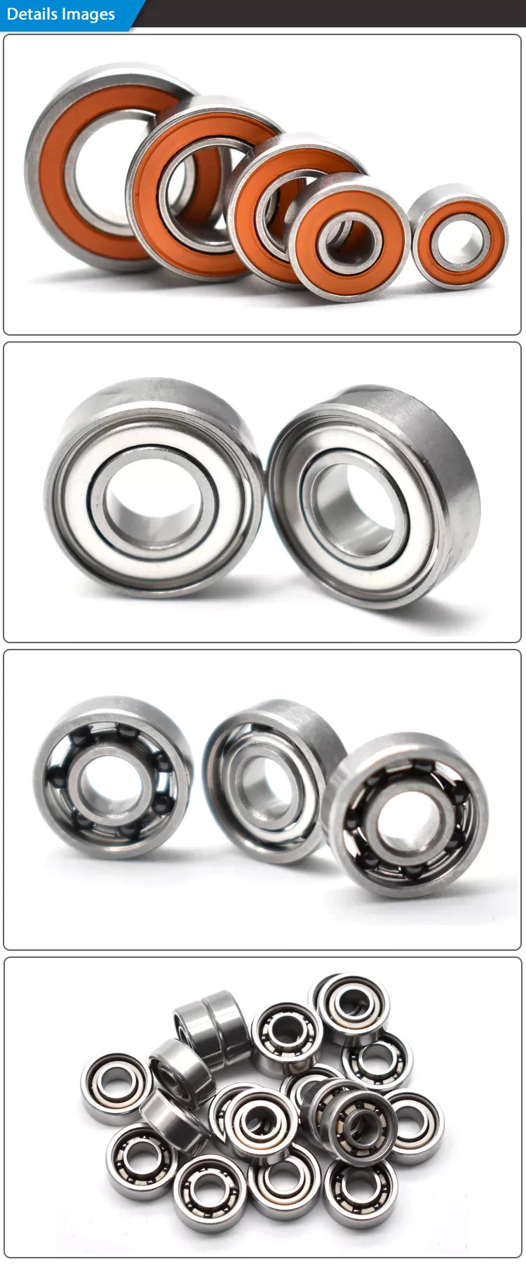
Small standard CX-LA series steel thin oil piston hydraulic cylinder 50mm 

Product Description

Solenoid valve:
1.High-strength aluminum alloy botton cover
2.One-time machining of valve lever by CN,high precision 
3.Valve body was machining by CNC.clean and beautifull
4.spacial processing of inner hole,small friction resistance and low starting pressure
5.High-precision pilot accessories .excitation time of only 0.05 seconds
6.imported seals ,the life up to 10 millions of times
7.Aluminum alloy piston is not easy to damage
8.Embedded copper nut not easy to loose
9.with a manual device for installaton and testing
10.Copper coil has avariety of voltage available for selection

Three basic types of pulleys, their applications and ideal mechanical advantages

There are 3 basic types of pulleys: movable, fixed and compound. Each has its advantages and disadvantages, and you should be able to judge which type is best for your needs by looking at the table below. Once you have mastered the different types of pulleys, you can choose the right pulley for your next project. Now that you have mastered the 3 basic types, it is time to understand their applications and ideal mechanical advantages.
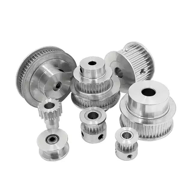
pulley

describe

The stress characteristics of a pulley depend on its size and construction. These stresses are derived by comparing the stress characteristics of different pulley designs. Stress criteria include static and fatigue strength analyses and specify maximum stress ranges. Stresses are calculated in a 3D stress field, including radial, tangential and axial stresses. The stress characteristics of pulleys are critical to the design and manufacture of industrial machines.
The principal stresses on the pulley shell are distributed in the tangential and hoop directions, close to the centerline of the pulley. If the pulley has a wide face, the axial stress occurring near the shell/disk junction can be large. The stress distribution was determined using British Standard BS5400 Part 10: Stresses at the shell and end disc connections for infinite fatigue life.
Another type of composite is a pulley with a belt section. Such structures are well known in the art. The corresponding help chapters for these elements contain detailed descriptions of the internal structure of these components. Chamfers between pulleys can also be defined using multiple tapers, with a smaller taper extending from midpoint 44 to large diameter 42. Additionally, the pulley can have multiple taper angles, and as the pulley moves away, the taper angle is from the center.

type

A pulley system uses a rope to move the object and 1 side of the rope to lift the load. The load is attached to 1 end of the pulley, while the other end can move freely in space. The force applied to the free end of the rope pulls the load up or down. Because of this, the mechanical advantage of the movable pulley is 2 to one. The greater the force applied to the free end of the rope, the greater the amount of movement achieved.
There are 3 common types of pulleys. The cast-iron variety has a rim at the front and a hub at the back. The arms of the pulley can be straight or curved. When the arms contract and yield instead of breaking, they are in tension. The top of the pulley centers the belt in motion and is available in widths ranging from 9mm to 300mm.
The rope, hub and axle are mounted on the pulley. They are common and versatile mechanical devices that make it easier to move or lift objects. Some pulleys change the direction of the force. Others change the magnitude. All types of pulleys can be used for a variety of different applications. Here are some examples. If you're not sure which type to choose, you can find more resources online.
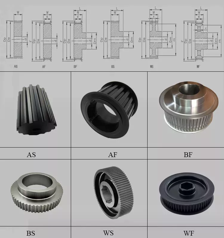
pulley

application

The applications for pulleys are almost limitless. This simple machine turns complex tasks into simple ones. They consist of a rope or chain wrapped around a wheel or axle. Using ropes, 1 can lift heavy objects without the enormous physical exertion of traditional lifting equipment. Some pulleys are equipped with rollers, which greatly magnifies the lifting force.
When used properly, the pulley system can change the direction of the applied force. It provides a mechanical advantage and allows the operator to remain separate from heavy objects. They are also inexpensive, easy to assemble, and require little lubrication after installation. Also, once installed, the pulley system requires little maintenance. They can even be used effortlessly. Despite having many moving parts, pulley systems do not require lubrication, making them a cost-effective alternative to mechanical lifts.
Pulleys are used in many applications including adjustable clotheslines in different machines, kitchen drawers and motor pulleys. Commercial users of pulley systems include cranes. These machines use a pulley system to lift and place heavy objects. They are also used by high-rise building washing companies. They can easily move a building without compromising its structural integrity. As a result, many industries rely on technology to make elevators easier.

Ideal mechanical advantage

The ideal mechanical advantage of a pulley system is the result of rope tension. The load is pulled to the center of the pulley, but the force is evenly distributed over the cable. Two pulleys will provide the mechanical advantage of 2 pulleys. The total energy used will remain the same. If multiple pulleys are used, friction between pulleys and pulleys reduces the return of energy.
Lever-based machines are simple devices that can work. These include levers, wheels and axles, screws, wedges and ramps. Their ability to work depends on their efficiency and mechanical superiority. The ideal mechanical advantage assumes perfect efficiency, while the actual mechanical advantage takes friction into account. The distance traveled by the load and the force applied are also factors in determining the ideal mechanical advantage of the pulley.
A simple pulley system has an MA of two. The weight attached to 1 end of the rope is called FA. Force FE and load FL are connected to the other end of the rope. The distance that the lifter pulls the rope must be twice or half the force required to lift the weight. The same goes for side-by-side pulley systems.

Materials used in manufacturing

While aluminum and plastic are the most common materials for making pulleys, there are other materials to choose from for your timing pulleys. Despite their different physical properties, they all offer similar benefits. Aluminum is dense and corrosion-resistant, and plastic is lightweight and durable. Stainless steel is resistant to stains and rust, but is expensive to maintain. For this reason, aluminum is a popular choice for heavy duty pulleys.
Metal can also be used to make pulleys. Aluminum pulleys are lightweight and strong, while other materials are not as durable. CZPT produces aluminium pulleys, but can also produce other materials or special finishes. The list below is just representative of some common materials and finishes. Many different materials are used, so you should discuss the best options for your application with your engineer.
Metals such as steel and aluminum are commonly used to make pulleys. These materials are relatively light and have a low coefficient of friction. Steel pulleys are also more durable than aluminum pulleys. For heavier applications, steel and aluminum are preferred, but consider weight limitations when selecting materials. For example, metal pulleys can be used in electric motors to transmit belt motion.
pulley

cost

Replacing a tensioner in a car's engine can cost anywhere from $90 to $300, depending on the make and model of the car. Cost can also be affected by the complexity of the pulley system and how many pulleys are required. Replacement costs may also increase depending on the severity of the damage. The cost of replacing pulleys also varies from car to car, as different manufacturers use different engines and drivetrains.
Induction motors have been an industrial workhorse for 130 years, but their cost is growing. As energy costs rise and the cost of ownership increases, these motors will only get more expensive. New technologies are now available to increase efficiency, reduce costs and improve safety standards.
The average job cost to replace an idler varies from $125 to $321, including labor. Parts and labor to replace a car pulley can range from $30 to $178. Labor and parts can cost an additional $10 to $40, depending on the make and model of the car. But the labor is worth the money because these pulleys are a critical part of a car's engine.

China OEM Small Standard Cx-La Series Steel Thin Oil Piston Hydraulic Cylinder 50mm     with high qualityChina OEM Small Standard Cx-La Series Steel Thin Oil Piston Hydraulic Cylinder 50mm     with high quality

China high quality Standard Small Hydraulic Cylinder for Farming Machine with Hot selling

Product Description

Standard Small Hydraulic Cylinder For Farming Machine


  • Product information


  • Specification


Material


Tube - Cold Drawn / Honed Tubing 

Piston Rod - Chromed, ground & polished 45#steel

Rod Seals - Polyurethane U-Cap 

End Caps - Steel, threaded fixed

Wear Ring - Nylon Backup Washer 

Mounts - Trunnion with angular Swivels 

Application


Agriculture, Concrete & Asphalt, Cranes, Fire & Rescue,Forestry & Logging,Mining

 & Rock Crushing,Oil & Gas,Snow & Ice Control,Waste 

Management and Material Recycling Industry , Engineering Equipment, Special

 Vehicle, Fitness equipment


Feature

1.High quality with a reasonable price

2.ISO9001-2008

3.Customized specification are accepted

Payment

T/T;L/C,WESTERN UNION

Port

HangZhou/ZheJiang , China

Quotation

According to the specific request

MOQ

According to the product

Packaging


metal case;plywood case;carton or as requirement 

Delivery time

30days upon receipt of 30% deposit; or upon receipt of relevant L/C;


  • About us

We specialize in this line for more than 20 years and trader with main products as follows: hydraulic cylinders, hydraulic power units, hydraulic manifolds-blocks, hydraulic flanges,pneumatic cylinders and custom-made components and parts, like industrial valves.

Our sales markets have covered North America, Europe, Australia, Japan and ect.


  • Working Process
  • Packaging & shipping

  • FAQ

Q1: Do you accept OEM manufacturing?

A1: Yes! We do accept OEM manufacturing. We will quote you the exact price and make the exact cylinder according to your specification and drawing.
 

Q2: Can we design our own package or print our own logo?

A2: Yes! Package and logo will be made acording to your requirements. 
 

Q3: Could we get small quantity samples?

A3: Yes! We understand the quality test is important and we are glad to make the sample for you. The MOQ is 1pcs.
 

Q4: How long is the production time?

A4: Generally the production time is 30 days. 
 

 Q5: What is the warranty?

 A5: 12 months against B/L date.


Contact me, any comments will be appreciated.

                                 Ellen Wang 


Benefits and Uses of Miter Gears

If you've ever looked into the differences between miter gears, you're probably wondering how to choose between a Straight toothed and Hypoid one. Before you decide, however, make sure you know about backlash and what it means. Backlash is the difference between the addendum and dedendum, and it prevents jamming of the gears, protects the mating gear surfaces, and allows for thermal expansion during operation.
gear

Spiral bevel gears

Spiral bevel gears are designed to increase efficiency and reduce cost. The spiral shape creates a profile in which the teeth are cut with a slight curve along their length, making them an excellent choice for heavy-duty applications. Spiral bevel gears are also hypoid gears, with no offsets. Their smaller size means that they are more compact than other types of right-angle gears, and they are much quieter than other types of gear.
Spiral bevel gears feature helical teeth arranged in a 90-degree angle. The design features a slight curve to the teeth, which reduces backlash while increasing flexibility. Because they have no offsets, they won't slip during operation. Spiral bevel gears also have less backlash, making them an excellent choice for high-speed applications. They are also carefully spaced to distribute lubricant over a larger area. They are also very accurate and have a locknut design that prevents them from moving out of alignment.
In addition to the geometric design of bevel gears, CZPT can produce 3D models of spiral bevel gears. This software has gained widespread attention from many companies around the world. In fact, CZPT, a major manufacturer of 5-axis milling machines, recently machined a prototype using a spiral bevel gear model. These results prove that spiral bevel gears can be used in a variety of applications, ranging from precision machining to industrial automation.
Spiral bevel gears are also commonly known as hypoid gears. Hypoid gears differ from spiral bevel gears in that their pitch surface is not at the center of the meshing gear. The benefit of this gear design is that it can handle large loads while maintaining its unique features. They also produce less heat than their bevel counterparts, which can affect the efficiency of nearby components.

Straight toothed miter gears

Miter gears are bevel gears that have a pitch angle of 90 degrees. Their gear ratio is 1:1. Miter gears come in straight and spiral tooth varieties and are available in both commercial and high precision grades. They are a versatile tool for any mechanical application. Below are some benefits and uses of miter gears. A simple explanation of the basic principle of this gear type is given. Read on for more details.
When selecting a miter gear, it is important to choose the right material. Hard faced, high carbon steel is appropriate for applications requiring high load, while nylon and injection molding resins are suitable for lower loads. If a particular gear becomes damaged, it's advisable to replace the entire set, as they are closely linked in shape. The same goes for spiral-cut miter gears. These geared products should be replaced together for proper operation.
Straight bevel gears are the easiest to manufacture. The earliest method was using an indexing head on a planer. Modern manufacturing methods, such as the Revacycle and Coniflex systems, made the process more efficient. CZPT utilizes these newer manufacturing methods and patented them. However, the traditional straight bevel is still the most common and widely used type. It is the simplest to manufacture and is the cheapest type.
SDP/Si is a popular supplier of high-precision gears. The company produces custom miter gears, as well as standard bevel gears. They also offer black oxide and ground bore and tooth surfaces. These gears can be used for many industrial and mechanical applications. They are available in moderate quantities from stock and in partial sizes upon request. There are also different sizes available for specialized applications.
gear

Hypoid bevel gears

The advantages of using Hypoid bevel and helical gears are obvious. Their high speed, low noise, and long life make them ideal for use in motor vehicles. This type of gear is also becoming increasingly popular in the power transmission and motion control industries. Compared to standard bevel and helical gears, they have a higher capacity for torque and can handle high loads with less noise.
Geometrical dimensioning of bevel/hypoid bevel gears is essential to meet ANSI/AGMA/ISO standards. This article examines a few ways to dimension hypoid bevel and helical gears. First, it discusses the limitations of the common datum surface when dimensioning bevel/helical gear pairs. A straight line can't be parallel to the flanks of both the gear and the pinion, which is necessary to determine "normal backlash."
Second, hypoid and helical gears have the same angular pitch, which makes the manufacturing process easier. Hypoid bevel gears are usually made of 2 gears with equal angular pitches. Then, they are assembled to match 1 another. This reduces noise and vibration, and increases power density. It is recommended to follow the standard and avoid using gears that have mismatched angular pitches.
Third, hypoid and helical gears differ in the shape of the teeth. They are different from standard gears because the teeth are more elongated. They are similar in appearance to spiral bevel gears and worm gears, but differ in geometry. While helical gears are symmetrical, hypoid bevel gears are non-conical. As a result, they can produce higher gear ratios and torque.

Crown bevel gears

The geometrical design of bevel gears is extremely complex. The relative contact position and flank form deviations affect both the paired gear geometry and the tooth bearing. In addition, paired gears are also subject to process-linked deviations that affect the tooth bearing and backlash. These characteristics require the use of narrow tolerance fields to avoid quality issues and production costs. The relative position of a miter gear depends on the operating parameters, such as the load and speed.
When selecting a crown bevel gear for a miter-gear system, it is important to choose 1 with the right tooth shape. The teeth of a crown-bevel gear can differ greatly in shape. The radial pitch and diametral pitch cone angles are the most common. The tooth cone angle, or "zerol" angle, is the other important parameter. Crown bevel gears have a wide range of tooth pitches, from flat to spiral.
Crown bevel gears for miter gear are made of high-quality materials. In addition to metal, they can be made of plastic or pre-hardened alloys. The latter are preferred as the material is less expensive and more flexible than steel. Furthermore, crown bevel gears for miter gears are extremely durable, and can withstand extreme conditions. They are often used to replace existing gears that are damaged or worn.
When selecting a crown bevel gear for a miter gear, it is important to know how they relate to each other. This is because the crown bevel gears have a 1:1 speed ratio with a pinion. The same is true for miter gears. When comparing crown bevel gears for miter gears, be sure to understand the radii of the pinion and the ring on the pinion.
gear

Shaft angle requirements for miter gears

Miter gears are used to transmit motion between intersecting shafts at a right angle. Their tooth profile is shaped like the mitre hat worn by a Catholic bishop. Their pitch and number of teeth are also identical. Shaft angle requirements vary depending on the type of application. If the application is for power transmission, miter gears are often used in a differential arrangement. If you're installing miter gears for power transmission, you should know the mounting angle requirements.
Shaft angle requirements for miter gears vary by design. The most common arrangement is perpendicular, but the axes can be angled to almost any angle. Miter gears are also known for their high precision and high strength. Their helix angles are less than 10 degrees. Because the shaft angle requirements for miter gears vary, you should know which type of shaft angle you require before ordering.
To determine the right pitch cone angle, first determine the shaft of the gear you're designing. This angle is called the pitch cone angle. The angle should be at least 90 degrees for the gear and the pinion. The shaft bearings must also be capable of bearing significant forces. Miter gears must be supported by bearings that can withstand significant forces. Shaft angle requirements for miter gears vary from application to application.
For industrial use, miter gears are usually made of plain carbon steel or alloy steel. Some materials are more durable than others and can withstand higher speeds. For commercial use, noise limitations may be important. The gears may be exposed to harsh environments or heavy machine loads. Some types of gears function with teeth missing. But be sure to know the shaft angle requirements for miter gears before you order one.

China high quality Standard Small Hydraulic Cylinder for Farming Machine     with Hot sellingChina high quality Standard Small Hydraulic Cylinder for Farming Machine     with Hot selling

China high quality Pancake Design for Small Space Hydraulic Jack Cylinder near me factory

Product Description

Specification:
1.With lock function.
2.durable high-strength alloy body
3.surface paint, unti-corrosion.
4.dust cap and quick links for various models  
5.dust seals to reduce pollution and extend cylinder life 
6.mounting position is free to any place.
7.Single acting hydraulic jack, spring return.
8. customer Tapping Hole on the top for fixing base

Model Pressure
@700bar
tons (kN)
Stroke
(mm)
Effective area
 (cm 2)
Oil
capacity
(cm3 )
Closed Height
A(mm)
Extending height
B(mm)
Out diameter
D(mm)
Weight
(kg)
CLP-602 65(578) 50 86.6 433 125.2 175.3 140.2 15.0
CLP-1002 115718) 50 146.8 734 137.2 187.2 175.3 25.9
CLP-1602 170(1511) 45 231.3 1040 148.1 193.0 220.2 44.0
CLP-2002 220(1955) 45 285.6 1284 155.2 200.2 245.1 56.8
CLP-2502 280(2489) 45 366.8 1649 159.3 204.2 275.3 74.0
CLP-4002 430(3822) 45 559.5 2515 178.1 223.3 350.3 133.9
CLP-5002 560(4977) 45 730.6 3285 192.3 237.2 400.3 188.9

Established in 2009, BAIER Hydraulic Power(HangZhou) Co., Ltd. is an professional leading manufacture of hydraulic tools in China. Such as hydraulic torque wrench, hydraulic cylinders, hydraulic nut splitter, hydraulic gear pullers, hyraulic pumps, etc. 

Our products have been widely used in petrochemical, cement, shipbuilding, steel plant, and heavy constructions areas, etc.
Besides, we have gained CE and ISO9001 certificates. 

Our Factory:
We has established an factory base covering a gross area of 8200 square meters in Xihu (West Lake) Dis. District, HangZhou City, responsible for manufacturing.

Our main product category includes:
Hydraulic cylinders and jacks
Hydraulic bolting tools such as hydraulic torque wrench
Hydraulic pumps
Hydraulic bolt tensioners, nut splitters.

Our Clients:
Our clients includes many big Chinese industrial companies, such as China Petroleum, Baosteel, Sinopec, China State Grid, Xihu (West Lake) Dis. Shipyards, CZPT Group, China Railway Construction Corporation.

Thanks for your time!


Agricultural Parts and How They Work

The term "agricultural parts" covers many different mechanical devices used in agriculture. Agricultural machinery includes power tools, tractors, and countless other farm implements. Aside from these, it also covers hand tools. Here are some common examples of agricultural parts. Read on to learn more. Below are some common parts and how they work. If you own a tractor, consider purchasing a new set of agricultural parts. Just-in-time delivery is an excellent option for a quick turnaround on parts and components.
agriculturalparts

Steel

Steel agricultural parts are used in the production of many types of agricultural machinery. They are used in tractors, combine harvesters, balers, mowers, and more. Because of the high wear resistance and tensile strength of steel, these parts require special properties. One such metal is Robalon. A short overview of this material is given below. To learn more about its benefits and application, read on. Here is a look at the qualities of Robalon.
Different steels are used for the housing of the Gearbox. Different manufacturers have different requirements. In addition to being lightweight and durable, steel agricultural parts must meet different material standards to perform their functions well. When choosing steel for your gearbox, keep these factors in mind. In addition to the weight and strength, you should also consider the type of gearbox. Gearbox housing is the first part that gets ruined in your tractor. If you buy a cheap steel housing, it will have poor quality.
Other benefits of steel include its resistance to chemical pesticides and its malleability. Steel also makes soil and dirt easier to wipe off. In addition to being corrosion-resistant, steel is also 100% recyclable. Its antimicrobial properties may also make it suitable for outdoor use. So, if you are looking for agricultural equipment parts, choose a steel farm machinery manufacturer. The benefits of steel agricultural parts are many. You can use them in the construction of various types of agricultural equipment.
Boron steel has many benefits in agricultural equipment. Boron steel is a good option for agricultural machinery parts, because of its high resistance to rust and corrosion. It is also very resistant to heat, which saves farmers a lot of time and money in replacing parts. In addition to its corrosion-resistant properties, boron steel also possesses great abrasion and heat resistance. It also is a good option for agricultural equipment that requires heavy loads.

Structural steel

Agricultural buildings made of structural steel are designed to hold livestock and agricultural equipment while remaining secure. These structures are lightweight and sturdy, offering a high level of thermal performance and insulation continuity. They are durable, sturdy, and rot/pest resistant, which makes them an excellent choice for many agricultural applications. Agricultural buildings made of structural steel can be easily customized, and you can choose from a variety of accessories, such as second-floor mezzanines, mansard systems, walk-through doors, and more. They can easily be altered to suit any renovation or change in business needs.
Today, high-strength steel is an excellent choice for structural parts in agricultural machinery. It allows agricultural equipment to withstand virtually any environmental condition, and its well-designed components increase reach and lifting capacity while maintaining strength and stability. As harvesters become more complex and cover more acres per hour, the need for reliable fabrication becomes increasingly more essential. In addition to harvesters, sprayers are a great example of tractors that make use of structural steel.
In addition to using structural steel for agricultural parts, agricultural tools are made from this metal, which reduces the construction time and waste by up to 30%. Many of these parts are made from structural steel, and a specialized company can provide you with the parts you need. For more information about industrial structural steel, please visit Benchmark Fabricated Steel or visit their website. There are many advantages of using steel in agricultural parts.
In addition to the benefits of using structural steel in agricultural applications, agricultural equipment can be built using aluminum alloys and other lightweight metals. Aluminum alloys, for instance, are lighter than steel, which is a great benefit in terms of reducing the weight of farm machinery and soil. Additionally, aluminum alloys are harder than steel, which makes them the ideal choice for dust-filled environments. Further, agricultural equipment can be designed with composite materials and can be made of aluminum or manganese.
agriculturalparts

Torsional dampers

If you're in the market for a new torsional damper, the best solution might be a bolt-on unit. These units are based on steel spring damper technology, which is also used in clutch disks. They are resistant to temperature-induced aging processes. ZF's solution, DynaDamp, utilizes the same technology as its Dual Mass Flywheel. There are several different sizes available to match the horsepower output of your tractor.
New regulations for tractors have increased demand for torsion control and dampers. Agricultural equipment, such as tractors, is being forced to use cleaner engines to reduce emissions. A torsional damper prevents vibration from spreading throughout the transmission and the rest of the vehicle. These parts can also come in straight spring and arc spring designs. Those with straight springs are the most common, while arc springs are used in agricultural applications.
Hydrodamp agricultural parts are designed to meet the technical demands of today's tractors. Agricultural parts, such as clutch disks, require a high level of protection against torsional vibration. Hydrodamp torsional dampers reduce vibration in the power train, protecting engine components and reducing operator fatigue. Hydrodamp torsional dampers offer low cost and high-performance solutions that can handle any drivetrain application.
Voith Hydrodamp torsional vibration dampers provide hydraulic damping for drive train vibrations and isolation. These units are maintenance-free and can protect against overloads and extend the service life of all components. The hydrodamp has 3 series - engine torques up to 3,700 Nm; vehicle-specific; and application-specific. For the ultimate in performance and dependability, Voith Hydrodamp is the only choice.

Just-in-time delivery

Just-in-time delivery of agricultural parts has become a widely used practice throughout industries. In agricultural production, for example, inputs for implements were in trucks on the day of their delivery and would be delivered to the farm at precisely the right time. This process has become widespread, reducing the need for costly inventories and lowering production, storage, and purchase costs for end-users. Here are 5 examples of how it can help farmers and other businesses.
A typical tractor has over 1,700 components. Increasing competition among automakers has forced manufacturers to move toward just-in-time delivery of agricultural parts. However, this approach fails if a single part fails to deliver the desired results. Farmers have had problems with shaft breaks in their planters, for instance. By using just-in-time delivery, these dealers avoid the problems associated with a last-minute purchase and focus on making the equipment work properly.
A major challenge of this type of supply chain is predicting demand. While JIT delivery can significantly reduce costs, the difficulty of predicting demand is significant. Suppliers must be able to deliver parts in time, ensuring maximum profitability. Agricultural companies must ensure that their suppliers understand demand and have good relationships with their customers. In this way, the cost of inventory management is reduced. And a single, well-designed supply chain can reduce costs.
In order to implement just-in-time delivery, businesses must be able to identify what customers need and how quickly they can supply it. Without such a service, companies may face huge risks. They may have to sacrifice supply, certain products, or entire customer bases. These costs cannot be measured and are therefore unwelcome by many companies. However, JIT can help improve profitability and market share. A comprehensive logistics provider such as Hollingsworth will provide operational procedures and resources for implementing JIT in a business.
agriculturalparts

Precision-based tech

Agricultural production is increasingly relying on technology for the benefit of farmers and their crops. The underlying science behind precision farming uses computer software and sensors to detect and improve soil conditions. With nearly 475 million farm households around the world, precision agriculture is important, as many of these operations are small and lack resources. The technology is also relevant to farms in developed countries that employ large production systems. However, implementing precision farming may be too expensive for small farms.
The goal of precision agriculture is to increase crop productivity and efficiency while protecting the environment. The use of technology helps farmers make better decisions on when to plant their crops, which can improve yield and quality, as well as cut greenhouse gas emissions. By incorporating precision technology into farming, farmers can use data from the field to plan for the future. Precision agriculture can be used in large and small fields. Precision farming can also help farmers monitor and optimize soil conditions and apply fertilizer at the proper time.
Agricultural equipment must be able to communicate with each other. With the help of machine learning and artificial intelligence, companies can process billions of data points and find meaningful patterns and drivers. This technology is particularly suited to precision agriculture, as data points from the field can include a wide range of environmental factors, including water levels and soil conditions. When smart computer algorithms analyze all this data, they can make intelligent recommendations on crop yield and quality.
Using precision technology for agricultural operations is essential for maximizing crop yield and quality. It can save time and money by optimizing irrigation systems, minimizing crop damage, and improving production. Precision technology can also help farmers reduce the amount of resources used to produce a particular crop. A small farmer can increase the output of a crop while minimizing waste and maximizing profits. With the use of these technologies, farming can be more productive and environmentally sustainable.

China high quality Pancake Design for Small Space Hydraulic Jack Cylinder     near me factory China high quality Pancake Design for Small Space Hydraulic Jack Cylinder     near me factory

China best 3kg Small Low Pressure CZPT Gas Cylinder / Hydraulic Gas Cylinder for Philippines wholesaler

Product Description

3KG Small Low Pressure Camping Gas Cylinder / Hydraulic Gas Cylinder for Philippines

Standard

  ISO4706, ISO9001:2008, CE,NIS 69, DOT 4BA, PNS 03-1, AS 2469.....

Material

  HP295 hot rolled steel 

Test Pressure

  30Bar

Work Pressure

  18Bar, 

Blasting Pressure

  60Bar

Wall Thickness

  ≥2.5mm

Tare weight

  3kgs

Valve

  Optional

Relevant Products

  Low pressure regulator, PVC hose, gas stove, Cast iron stove


LPG-3KG  lpg cylinder

Water

Capacity

High total(mm)

BOTTLE

GUARDED

BASE

In diameter (mm)

High

Outside diameter(mm)

High

Outside diameter(mm)

High

7.2L

290

φ230

210

205

66

φ225

42


Daly, 1 of the largest LPG Cylinders in China, was founded in 1981. Daly is the Deputy Director Unit of The China Gas Association involved in the formulation and modification of Chinese National Standard in LPG industry. Today Daly is CZPT to produce over 5  million cylinders yearly and has with excellent reputation for LPG cylinders and export the products to Europe, Africa, Southeast Asia, South America and etc. Our products cover the whole range of LPG cylinders, range from 3kg, 5kg, 6kg, 10kg, 12.5kg to 60kg and comply with different standards, like ISO4706/EN1442/GB5842/DOT4BA and etc.


Exhibition


ZheJiang Daly LPG Cylinder manufacturer, we are NO 3 LPG Cylinder manufacturer in China.

Our product is in millions Chinese family which is safe and strong. In China,  

only few manufacturers have the permit to make the LPG Cylinder, we are 1 of them.


OUR FAQ


Question 1. How to ensure your cylinders quality?

A: Our factory was founded in 1981, we have ISO9001, BV, CE, and approved by the Administration of quality of supervision, Inspection and Quarantine (AQSIQ) of China. HangZhou is an appointed manufacturer of LPG cylinders and pressure vessels. Moreover, HangZhou is a deputy director's unit of the China Association-Professional Committee of Chinese LPG cylinders.


We have 9 pressure vessel production lines, which are of the most advanced technology in the industry and furnished with early 400 machinery and equipment (including advanced x-ray real-time Image Inspection System, Spectrum Analyzer, and other inspection equipment).


Question 2 What's your production capacity?

A: We have 9 production lines, in full production capacity, we can supply 5 million cylinders annually / 400,000 cylinders per month.


Question 3. What's Daly Main Sales Products?

A: We mainly supply LPG cylinder, valve and other parts of cylinder.


Question 4. How about the sample?

A: In our acceptable range, we can offer a sample by charging freight, and we will return the fee to your after you make an order.


Question 5. How about the payment and delivery time?

A: The payment term: 30% for deposit, balance copy of BL; L/C at sight.


Question 6. How do you make our long-term business and good relationship?

A: 1. We keep good quality and competitive price to ensure our customers' benefit.

   2. We will have professional engineers and advanced production equipment, will offer you as much support as we can to help you occupy more market. 

Advantages of Ball Bearings

What is a ball bearing? A ball bearing is a type of rolling-element bearing that utilizes balls to maintain separation between 2 bearing races. Its contact angle between the balls and the races helps it reduce friction between the loads. There are several advantages to ball bearings, including their ability to withstand water. Read on to learn more. Here are a few of the benefits. You can use them in your daily life, from your car to your boat.

Ball bearings reduce friction between loads

Ball bearings reduce friction between loads by constraining the relative motion between moving parts. These bearings consist of a ring of small metal balls that reduce friction between moving objects. The name "ball bearing" is derived from the verb "to bear." The lubricant within the bearing reduces friction between moving particles. In a machine, ball bearings reduce friction between moving parts and improve linear motion around a fixed axis.
These bearings are commonly used to reduce friction between loads in rotating machines. They have 2 tracks, 1 fixed to the rotating part and 1 stationary. The rolling balls of a ball bearing have lower friction than flat surfaces. Because of this, they are useful for bar stool bearings. They reduce friction between surfaces and maintain the separation between bearing races. Hence, minimal surface contact is possible. Ball bearings have the potential to increase the life of machines and reduce energy consumption.
Ball bearings can be as small as a wrist watch or as large as an industrial motor. They function the same way, reducing friction between loads. Among their many uses, ball bearings are essential for everyday operations. Clocks, air conditioners, fans, and automobile axles all use ball bearings. In fact, anything that uses a motor requires ball bearings. It's no wonder they're gaining popularity in industries and everyday life.
bearing

They support radial and axial loads

Radial ball bearings are used primarily for radial loads, but they also have a capacity for axial load. This load capacity is usually given as a percentage of the radial load rating. Axial load capacity is generally greater for a bearing with a larger difference between the inner and outer ring diameters. The axial load capacity is also affected by the bearing's raceway depth, with shallow raceways being more suitable for heavier axial loads.
The 2 main types of axial and radial loads are defined by their orientation. Axial loads apply forces in 1 direction while radial loads act on the opposite direction. In both cases, the bearing must support the forces that are imposed. Axial loads apply forces to a bearing in a single direction, while radial loads apply forces in both directions. Regardless of the type of load, axial and radial loads should be considered when selecting a bearing for a given application.
Angular and radial ball bearings differ in their materials. Radial ball bearings are made largely of through-hardened materials. They typically have a Rockwell hardness rating of 58 Rc. The raceways and balls of these bearings are made of 440C stainless steel. They may also contain shields and seals. SAE 52100 steel is the most common material for the raceway, while molybdenum steels are excellent for high temperatures.

They have a contact angle between the balls and the races

When comparing axial load bearings with their radial counterparts, the angular contact angle is more important. Axial load bearings, have a contact angle between the balls and the races of 35 degrees. They are suitable for axial loads and a limited radial load. The contact angle of these bearings is a result of the shape of the inner and outer rings. Each rolling element comes into contact with the inner and outer rings only at 1 point, forming a 30 degree angle with the radial plane. The radial force of the axial load on these bearings is therefore increased by increasing the contact angle between the balls and the races.
This contact angle determines the amount of friction between the balls and the races, and allows angular contact bearings to withstand heavy radial and thrust loads. In addition, the larger the contact angle, the greater the axial load support. Angular contact bearings come in standard imperial (inch) and metric (mm) sizes. The angular contact angle is determined by the free radial play value and the curvature of the inner track.

They are water-resistant

In addition to their water-resistant qualities, corrosion-resistant ball bearings can also protect against the damaging effects of corrosive environments. Generally, standard metals, such as steel, are susceptible to rust, which can significantly reduce their performance and extend the life of parts. However, plastics, stainless steel, and ceramics can provide corrosion-resistant ball bearings. And because these materials are much more durable, they offer other advantages, such as being easy to maintain.
Among the advantages of plastic ball bearings is their high resistance to extreme temperatures, high speeds, and corrosion. Depending on their construction, plastic bearings are often able to resist corrosion and anti-static properties. They're lightweight and inexpensive compared to steel ball bearings. CZPT Sales Corporation was established in 1987 with a modest turnover of 4 lacs. As of the last financial year, it has grown to 500 lacs in sales.
Other advantages of water-resistant ball bearings include corrosion resistance, which is a key consideration in many applications. While stainless steel is highly corrosion-resistant, it decreases the bearing's load-carrying capacity. Also, corrosion-resistant deep groove ball bearings are usually made with a specified internal clearance, which absorbs loss in clearance during mounting and shaft expansion. This factor affects their performance, and if these are compromised, a replacement may be necessary.
bearing

They are tough

A few things make ball bearings tough: they're made of real materials, which means that they have inherent imperfections. Grade-1 balls are made especially for high-stress applications, such as Formula One engines. Grade-3 balls, on the other hand, strike the perfect balance between performance and cost. Ceramic balls, for example, are made to spin at a high rate of 400 RPM, and they're finished with a mirror finish.
A steel carbon ball bearing is 1 of the toughest forms of ball bearings available. The material is incredibly strong, but the contact between the balls isn't the best. Low-carbon steel is best for linear shafting and is usually coated with a polymer to prevent damage. Steel ball bearings with moderate amounts of carbon are tough, durable, and water-resistant. They're ideal for gears, but their high-carbon steel counterparts are particularly tough and can resist corrosion.
A ceramic ball bearing is another option. This type has steel inner and outer rings but ceramic balls. Ceramic balls can withstand higher temperatures than steel and are also electrically insulating. Ceramic ball bearings also tend to be lighter and are more resistant to wear and tear. They're also ideal for applications in which grease is not an option, such as in space shuttles. Despite the fact that ceramic ball bearings are tough, they're still cheaper than steel ball bearings.

They are conductive

You may have heard the term "ball bearing" if you've studied introductory physics. What does that mean? Essentially, ball bearings are conductive because of their ability to conduct electricity. This ability is reflected in the charge distribution on the surface of the ball. Positive charges are drawn toward the positive plate, while negative charges are drawn away from the positively charged ball bearing. You may have even seen a ball bearing in action.
However, despite their conductive nature, ball bearings can still become damaged by electrical discharge. A higher voltage can cause the balls to pit, and the raceways to become uneven. These uneven surfaces will first show up as excessive noise, and eventually cause the bearing to malfunction. Fortunately, engineers have found a way to counter this problem: conductive grease. This grease enables current to flow through the ball bearing, preventing both heat and voltage buildup.
The difference between steel and ceramic ball bearings is their density. Steel bearings are more conductive than glass or hybrid ceramics. Steel ball bearings have an even grain structure and are conductive for resonance flow. When moving fast, the air surrounding the steel ball bearing carries resonance from the inner ring to the outer. This makes them ideal for high-speed resonance transfer. In addition to being conductive, glass microbeads are harder and lighter than steel.
bearing

They are used in pulley systems

Pulley systems use ball bearings to move the sprocket, which is a wheel that rotates. These bearings are installed on the center mounting hole of the pulley wheel. They protect the entire system from heat, while allowing higher speed and smooth operation. They distribute the weight of the load evenly, minimizing friction and wobbling, and ensure a smooth rotation. Ball bearings are typically made from steel and are installed inside the pulley wheel.
The moment of inertia and bearing friction are measured to within 10 percent accuracy. These 2 variables affect the speed of the pulley system, which can lead to crashes if the weight holders are not balanced. Therefore, ball bearings are used to minimize the chance of such crashes. When you want to know more about ball bearings in pulley systems, here are the advantages they provide.
Another benefit of ball bearings in pulley systems is that they have lower friction than their solid counterparts. In order to reduce friction, however, ball bearings must be made of good materials. Some of the common ball materials are high-quality plastics and stainless steel. Good materials and clever block design are essential to minimizing friction. If you are planning to use ball bearings in your pulley system, check out the following tips and make sure you are choosing the right 1 for your application.
China best 3kg Small Low Pressure CZPT Gas Cylinder / Hydraulic Gas Cylinder for Philippines     wholesaler China best 3kg Small Low Pressure CZPT Gas Cylinder / Hydraulic Gas Cylinder for Philippines     wholesaler

China Good quality Hydraulic Rotary Damper Clothes Hook Handle Small Cylinder Damping Hinge Clamshell Slow Drop Silent Hinge with Great quality

Product Description

1.About size
You can customize various dampers with different dimensions and different forces according to your product structure, different functions, and different ranges of use.
 

2.About color
The surface treatment is galvanized and sprayed, and the color can be customized according to customer requirements.

3.About quality
Our factory has fully automatic numerical control torque testing equipment, 3 inspection procedures for each damper.

4.About delivery
The production cycle is 3000 pcs/two days, and the delivery is guaranteed on time.

HangZhou Manjia Youchuang Household Products Co., Ltd. is a professional dampers and lifting cabinet manufacturer which collects research,design,production and sale.Our technical backbone has been engaged in the R&D and production of dampers for more than 22 years experience.

The professional and well trained production department and QC staff could assure the perfect performance of our Dampers products. For the quality assurance rate of over 99.98%, and the stability of delivery time rate more than 99.96%.
Q1. Can I have a sample for testing?

A: Yes, samples are in stock, we will return sample fee back to you once you make a formal order from us.


Q2. What about the lead time?

A: There is a large amount of stock in the warehouse, welcome to order.


Q3. What is your MOQ?

A: We support small batch trial goods, welcome to order.


Q4. How do you ship the goods and how long does it take to arrive?
A: We have a dedicated freight forwarding company for transportation, and the freight is economical.


Q5. Can I print my logo on the product?

A: Yes. Please inform us formally before our production and confirm the design firstly based on our sample. Customized design is available. OEM and ODM are offered.


Q6. Do you offer guarantee for the products?
A: Yes, we offer 1 year warranty to our products.


Q7: How to deal with the faulty?

A: Our products are produced in strict quality control system and the defective rate will be less than 0.2%.During the guarantee period, we will send new dampers with new order for small quantity. For defective batch products, we will repair them and resend them to you or we can discuss the solution.


Mechanical advantages of pulleys

A pulley is a mechanical device used to transmit motion. The device has a variety of uses, including lifting heavy objects. In this article, we will discuss the mechanical advantages, types, common uses and safety considerations of pulleys. We'll also discuss how to identify pulleys and their components, and what to look out for when using pulleys. Read on to learn more about pulleys.
pulley

Mechanical advantages of pulleys

The mechanical advantage of pulleys is that they change the direction of force from 1 direction to another. In this way, the person lifting the heavy object can change its position with minimal effort. The pulleys are also easy to install and require no lubrication after installation. They are also relatively cheap. Combinations of pulleys and cables can be used to change the direction of the load.
The mechanical advantage of a pulley system increases with the number of ropes used in the system. The more cycles a system has, the more efficient it is. If the system had only 1 rope, the force required to pull the weight would be equal. By adding a second rope, the effort required to pull the weight is reduced. This increase in efficiency is known as the mechanical advantage of the pulley.
Pulleys have many uses. For example, ziplines are 1 application. This is a good example of pulleys in use today. Pulley systems can be complex and require a lot of space. Using ziplines as an example, advanced students can calculate the mechanical advantage of multiple pulleys by dividing the work done by each pulley by the remainder or fraction. Regents at the University of Colorado created a zipline with K-12 input.
Another use for pulleys is weight lifting. This technique is very effective when using multiple strands of rope. A single rope going from 1 pulley to the other with just 2 hands is not enough to lift heavy objects. Using a pulley system will greatly increase the force you receive. This power is multiplied over a larger area. So your lifting force will be much greater than the force exerted by a single rope.
The pulley is a great invention with many uses. For example, when lifting heavy objects, pulleys are a great way to get the job done, and it's easier to do than 1 person. The pulley is fixed on a hinge and rotates on a shaft or shaft. Then pull the rope down to lift the object. A pulley assembly will make the task easier. In addition, it will also allow power to be transferred from 1 rotary shaft to another.
pulley

Types of pulleys

If you are an engineer, you must have come across different types of pulleys. Some pulleys come in multiple types, but a typical pulley has only 1 type. These types of pulleys are used in various industrial processes. Here are some common types of pulleys that engineers encounter on the job. In addition to the above, there are many more. If you haven't seen them in practice, you can check out a list of the different types below.
Fixed pulleys: Fixed pulleys have a roller attached to a fixed point. The force required to pull the load through the fixed pulley is the same as the force required to lift the object. Movable pulleys allow you to change the direction of the force, for example, by moving it laterally. Likewise, movable pulleys can be used to move heavy objects up and down. Commonly used in multi-purpose elevators, cranes and weight lifters.
Composite pulleys combine fixed and movable pulleys. This combination adds to the mechanical advantage of both systems. It can also change the direction of the force, making it easier to handle large loads. This article discusses the different types of pulleys used for lifting and moving. Braided pulleys are an example of these pulleys. They combine the advantages of both types.
A simple pulley consists of 1 or more wheels, which allow it to reverse the direction of the force used to lift the load. On the other hand, dual-wheel pulleys can help lift twice the weight. By combining multiple materials into 1 pulley, a higher ME will be required. Regardless of the type of pulley, understanding the principles behind it is critical.
Pulleys are an important part of construction and mechanical engineering, and their use dates back to Archimedes. They are a common feature of oil derricks and escalators. The main use of pulleys is to move heavy objects such as boats. In addition to this, they are used in other applications such as extending ladders and lifting heavy objects. The pulley also controls the aircraft rudder, which is important in many different applications.

Commonly used

Common uses for pulleys are varied. Pulley systems are found throughout most areas of the house, from adjustable clotheslines to motor pulleys in different machines. Commercially, 1 of the most common uses is for cranes. Cranes are equipped with pulleys to lift heavy objects. It is also common to use pulley systems in tall buildings, which allow tall buildings to move with relative ease.
Pulleys are commonly used in interception and zipline systems, where a continuous rope around the pulley transmits force. Depending on the application, the rope is either light or strong. Pulleys are formed by wrapping a rope around a set of wheels. The rope pulls the object in the direction of the applied force. Some elevators use this system. Pull a cable on 1 end and attach a counterweight on the other end.
Another common use for pulleys is to move heavy objects. Pulleys mounted on walls, ceilings or other objects can lift heavy objects like heavy toolboxes or 2x4 planks. The device can also be used to transfer power from 1 rotating shaft to another. When used to lift heavy objects, pulleys can be used to help you achieve your goals of a good workout.
Pulley systems have a variety of uses, from the most basic to the most advanced. Its popularity is indisputable and it is used in different industries. A good example is timing belts. These pulleys transmit power to other components in the same direction. They can also be static or dynamic depending on the needs of the machine. In most cases, the pulley system is custom made for the job.
Pulley systems can be simple or complex, but all 3 systems transfer energy efficiently. In most cases, the mechanical advantage of a single pulley is 1 and the mechanical advantage of a single active pulley is 2. On the other hand, a single live pulley only doubles the force. This means you can trade effort for distance. Pulleys are the perfect solution for many common applications.
pulley

Safety Notice

If you use pulleys, you need to take some safety precautions. First, make sure you're wearing the correct protective gear. A hard hat is a must to avoid being hit by falling objects. You may also want to wear gloves for added protection. You should also maintain a good distance from the pulley so that nearby people can walk around it safely.
Another important safety measure to take before using a chain hoist is to barricade the area to be lifted. Use marker lines to prevent the load from sliding when moving horizontally. Finally, use only the sprocket set for vertical lift. Always install shackle pins before lifting. You should also wear personal protective equipment such as earplugs and safety glasses when using the chain hoist.
In addition to these safety measures, you should also use cables made from aerospace-grade nylon. They will last many cycles and are made of high quality materials. Also, make sure the cables are lubricated. These measures reduce friction and corrosion. No matter what industry you are in, be sure to follow these precautions to ensure a long service life for your cables. Consult the cable manufacturer if you are unsure of the appropriate material. A company with 60 years of experience in the cable industry can recommend the right material for your system.

China Good quality Hydraulic Rotary Damper Clothes Hook Handle Small Cylinder Damping Hinge Clamshell Slow Drop Silent Hinge     with Great qualityChina Good quality Hydraulic Rotary Damper Clothes Hook Handle Small Cylinder Damping Hinge Clamshell Slow Drop Silent Hinge     with Great quality

China Best Sales Roundline Small Piston Hydraulic RAM Oil Hydraulic Cylinder near me factory

Product Description

1.All cylinder in this series use carbon streel for both front/rear cover.

2.strong structure.

3.Medium carbon steel S45C is used for the piston rod,with hard chromate plated then polished to mirror class . lt has very high rigidity and resistance to erosion and corrosion.

4.The cylinder is mode by honed carbon steel tube.

5.Adjustable cushions and bleeding holes at both ends.

Specification

Cylinder bore 32,40,50,63,80,100,125,150,200,250,300
Tatal Stroke 10~1000
Maximum use pressure 350kgf/cm
Minimum use pressure 3kgf/cm
Actuation oil ISO Vg68
Speed range 8~400 mm/s
Operating temperature range -10~+200ºC


How to order

Broe Φ32,Φ40,Φ50,Φ63,Φ80,Φ100,Φ125,Φ150
Semsomh device(magnetic) with magnetic,without magnetic
Stroke 20~2000mm
Mounting accessories

basic type,Front flange mounting,front foot mounting,

center trunnion mounting,single swivel mounting,double swivel mounting

Rod accessories i type rod clevis,y type rod clevis
Oil port location custom made

Contact us to support customization

Packaging & Delivery

About Us

Youjiaxin is an experienced manufacturer specializes in CNC machining, CNC turning, stamping and laser cutting parts with different materials and many finished surface.

We are in the business of providing value-added services to assist you in completing your projects. The high quality and reliability of our service has enabled us to maintain long-standing relationships with our clients in various industries.

Rich experience, engineering expertise and high performance equipment help us in offering our customers top quality products.

If you have any question, please kindly refer to the FAQs below or contact us directly.

FAQ
 

  1. Do you accept OEM manufacturing?
    Yes! We do accept OEM manufacturing. so we can provide the best price as well as the first class service.
  2. Could we get small quantity samples?
    Yes! We understand the quality test is important and we are glad to make the sample for you. The MOQ could be 1pcs.
  3. Can you provide free sample? How long can we expect to get the sample?
    Sample can be free of charge if deposit for future order received. samples need 5-10days if need custom make . standard can be ship out in 2 days.
  4. How long is the production time?
    Normally about 30 days.
  5. What is the warranty?
    1year against B/L date.

How to Select a Worm Shaft and Gear For Your Project

You will learn about axial pitch PX and tooth parameters for a Worm Shaft 20 and Gear 22. Detailed information on these 2 components will help you select a suitable Worm Shaft. Read on to learn more....and get your hands on the most advanced gearbox ever created! Here are some tips for selecting a Worm Shaft and Gear for your project!...and a few things to keep in mind.
worm shaft

Gear 22

The tooth profile of Gear 22 on Worm Shaft 20 differs from that of a conventional gear. This is because the teeth of Gear 22 are concave, allowing for better interaction with the threads of the worm shaft 20. The worm's lead angle causes the worm to self-lock, preventing reverse motion. However, this self-locking mechanism is not entirely dependable. Worm gears are used in numerous industrial applications, from elevators to fishing reels and automotive power steering.
The new gear is installed on a shaft that is secured in an oil seal. To install a new gear, you first need to remove the old gear. Next, you need to unscrew the 2 bolts that hold the gear onto the shaft. Next, you should remove the bearing carrier from the output shaft. Once the worm gear is removed, you need to unscrew the retaining ring. After that, install the bearing cones and the shaft spacer. Make sure that the shaft is tightened properly, but do not over-tighten the plug.
To prevent premature failures, use the right lubricant for the type of worm gear. A high viscosity oil is required for the sliding action of worm gears. In two-thirds of applications, lubricants were insufficient. If the worm is lightly loaded, a low-viscosity oil may be sufficient. Otherwise, a high-viscosity oil is necessary to keep the worm gears in good condition.
Another option is to vary the number of teeth around the gear 22 to reduce the output shaft's speed. This can be done by setting a specific ratio (for example, 5 or 10 times the motor's speed) and modifying the worm's dedendum accordingly. This process will reduce the output shaft's speed to the desired level. The worm's dedendum should be adapted to the desired axial pitch.

Worm Shaft 20

When selecting a worm gear, consider the following things to consider. These are high-performance, low-noise gears. They are durable, low-temperature, and long-lasting. Worm gears are widely used in numerous industries and have numerous benefits. Listed below are just some of their benefits. Read on for more information. Worm gears can be difficult to maintain, but with proper maintenance, they can be very reliable.
The worm shaft is configured to be supported in a frame 24. The size of the frame 24 is determined by the center distance between the worm shaft 20 and the output shaft 16. The worm shaft and gear 22 may not come in contact or interfere with 1 another if they are not configured properly. For these reasons, proper assembly is essential. However, if the worm shaft 20 is not properly installed, the assembly will not function.
Another important consideration is the worm material. Some worm gears have brass wheels, which may cause corrosion in the worm. In addition, sulfur-phosphorous EP gear oil activates on the brass wheel. These materials can cause significant loss of load surface. Worm gears should be installed with high-quality lubricant to prevent these problems. There is also a need to choose a material that is high-viscosity and has low friction.
Speed reducers can include many different worm shafts, and each speed reducer will require different ratios. In this case, the speed reducer manufacturer can provide different worm shafts with different thread patterns. The different thread patterns will correspond to different gear ratios. Regardless of the gear ratio, each worm shaft is manufactured from a blank with the desired thread. It will not be difficult to find 1 that fits your needs.
worm shaft

Gear 22's axial pitch PX

The axial pitch of a worm gear is calculated by using the nominal center distance and the Addendum Factor, a constant. The Center Distance is the distance from the center of the gear to the worm wheel. The worm wheel pitch is also called the worm pitch. Both the dimension and the pitch diameter are taken into consideration when calculating the axial pitch PX for a Gear 22.
The axial pitch, or lead angle, of a worm gear determines how effective it is. The higher the lead angle, the less efficient the gear. Lead angles are directly related to the worm gear's load capacity. In particular, the angle of the lead is proportional to the length of the stress area on the worm wheel teeth. A worm gear's load capacity is directly proportional to the amount of root bending stress introduced by cantilever action. A worm with a lead angle of g is almost identical to a helical gear with a helix angle of 90 deg.
In the present invention, an improved method of manufacturing worm shafts is described. The method entails determining the desired axial pitch PX for each reduction ratio and frame size. The axial pitch is established by a method of manufacturing a worm shaft that has a thread that corresponds to the desired gear ratio. A gear is a rotating assembly of parts that are made up of teeth and a worm.
In addition to the axial pitch, a worm gear's shaft can also be made from different materials. The material used for the gear's worms is an important consideration in its selection. Worm gears are usually made of steel, which is stronger and corrosion-resistant than other materials. They also require lubrication and may have ground teeth to reduce friction. In addition, worm gears are often quieter than other gears.

Gear 22's tooth parameters

A study of Gear 22's tooth parameters revealed that the worm shaft's deflection depends on various factors. The parameters of the worm gear were varied to account for the worm gear size, pressure angle, and size factor. In addition, the number of worm threads was changed. These parameters are varied based on the ISO/TS 14521 reference gear. This study validates the developed numerical calculation model using experimental results from Lutz and FEM calculations of worm gear shafts.
Using the results from the Lutz test, we can obtain the deflection of the worm shaft using the calculation method of ISO/TS 14521 and DIN 3996. The calculation of the bending diameter of a worm shaft according to the formulas given in AGMA 6022 and DIN 3996 show a good correlation with test results. However, the calculation of the worm shaft using the root diameter of the worm uses a different parameter to calculate the equivalent bending diameter.
The bending stiffness of a worm shaft is calculated through a finite element model (FEM). Using a FEM simulation, the deflection of a worm shaft can be calculated from its toothing parameters. The deflection can be considered for a complete gearbox system as stiffness of the worm toothing is considered. And finally, based on this study, a correction factor is developed.
For an ideal worm gear, the number of thread starts is proportional to the size of the worm. The worm's diameter and toothing factor are calculated from Equation 9, which is a formula for the worm gear's root inertia. The distance between the main axes and the worm shaft is determined by Equation 14.
worm shaft

Gear 22's deflection

To study the effect of toothing parameters on the deflection of a worm shaft, we used a finite element method. The parameters considered are tooth height, pressure angle, size factor, and number of worm threads. Each of these parameters has a different influence on worm shaft bending. Table 1 shows the parameter variations for a reference gear (Gear 22) and a different toothing model. The worm gear size and number of threads determine the deflection of the worm shaft.
The calculation method of ISO/TS 14521 is based on the boundary conditions of the Lutz test setup. This method calculates the deflection of the worm shaft using the finite element method. The experimentally measured shafts were compared to the simulation results. The test results and the correction factor were compared to verify that the calculated deflection is comparable to the measured deflection.
The FEM analysis indicates the effect of tooth parameters on worm shaft bending. Gear 22's deflection on Worm Shaft can be explained by the ratio of tooth force to mass. The ratio of worm tooth force to mass determines the torque. The ratio between the 2 parameters is the rotational speed. The ratio of worm gear tooth forces to worm shaft mass determines the deflection of worm gears. The deflection of a worm gear has an impact on worm shaft bending capacity, efficiency, and NVH. The continuous development of power density has been achieved through advancements in bronze materials, lubricants, and manufacturing quality.
The main axes of moment of inertia are indicated with the letters A-N. The three-dimensional graphs are identical for the seven-threaded and one-threaded worms. The diagrams also show the axial profiles of each gear. In addition, the main axes of moment of inertia are indicated by a white cross.

China Best Sales Roundline Small Piston Hydraulic RAM Oil Hydraulic Cylinder     near me factory China Best Sales Roundline Small Piston Hydraulic RAM Oil Hydraulic Cylinder     near me factory

China high quality CZPT Binotto Penta Kind Under Body Umb Ume Micro Telescopic Hydraulic Cylinder for Small Light Duty 1 Ton 2 Ton 3 Ton 4 Ton 5 Ton Dump Truck and Tipper Trailer with Great quality

Product Description

micro telescopic hydraulic cylinder for dump truck and tipper trailer


Product Description


Hyva & CZPT & Custom hoist & Xihu (West Lake) Dis.r type micro telescopic hydraulic cylinder are used for Dump Truck, Tipper Truck, Trailer, Agricultural Machinery, Garbage Truck, Landing Platform etc.

Tsingshi hydraulic Customers,  MAN, JAC, VOLVO, SHACMAN, DAF, JMC,  HUNO, CIMC, SINOTRUK, TATRA,BENS,XIHU (WEST LAKE) DIS.FENG,  FOTON,etc.

1.Micro telescopic hydraulic cylinder Each stage electroplate hard chrome;
2.lighter and easier to maintenance;
3.High quality alloy seamless steel pipe have better mechanical properties;
4.The world famous brands of seals, such as HALLITE, PARKER,etc;
5.World-class processing technology ensures stable and reliable quality.


NO ITEM micro telescopic hydraulic cylinder DATA
1 Material Carbon Steel, Alloy Steel, 27SiMn,45#,20#,etc
2 Honed tube 40-300mm, Heat treatment, honing, rolling
3 Honed tube 30-280mm, plated nickel or hard Chrome or ceramic
4 Seal kit Parker, Merkel, Hallite, Kaden, etc
5 Coating Sandblasting, primer paint, middle paint, finish paint,
Color can paint according to customer demands.
6 Technology Parker,custom hoist, hyco,HYVA, Meiller

SAT,DAT

7 Mounting type Pin-eye , flange, trunnion mount,ball mount, screw thread.
FC, FE, FEE, FSE,TPIN
8 Working medium Hydraulic Oil
9 Working pressure 16-20Mpa mini telescopic hydraulic cylinder
10 Temperature range -50°C to +100°C

Detailed Photos


Company Profile

Tsingshi hydraulic is a hydraulic telescopic cylinder for dump tipper truck company which takes up with hydraulic design, R&D, manufacturer, sell and service hydraulic products-micro telescopic hydraulic cylinder.

-micro telescopic hydraulic cylinder Certification ISO9001 TS16949, etc;
-micro telescopic hydraulic cylinder Export to North America, South America, Australia, South Korea, Southeast Asia, South Africa, Europe, Middle East, etc;
-ODM&OEM micro telescopic hydraulic cylinder according to client's requirements;
-Professional manufacturer& supplier of micro telescopic hydraulic cylinder over 30 years;
-The micro telescopic hydraulic cylinder can be used for Dump Truck, Tipper Truck, Trailer, Agricultural Machinery, Garbage Truck,Landing Platform etc; We can produce the follow brand hydraulic cylinder. HYVA, BINOTTO, EDBRO, PENTA, MAILHOT, CUSTOM HOIST, MUNCIE, METARIS, HYDRAULEX GLOBAL, HYCO, PARKER, COMMERCIAL HYDRAULICS, MEILLER. WTJX, XT, JX, HCIC, ZX, SZ, SJ.


CUSTOMERS PHOTOS


QUALITY GUARANTEE


HIGH QUALITITY GUARANTEE-cylinder hydraulic telescopic for dump truck and tipper trailer
-7*24 service.
-Competitive price.
-Professional technical team.
-Perfect after-sales service system.
-ODM&OEM Hydraulic Cylinder according to customer needs.
-Strong Hydraulic Cylinder production capacity to ensure fast delivery.
-Guarantee Quality. Every process must be inspected, all products need be tested before leaving the factory.

< telescopic hydraulic cylinder Leak Test

<mini telescopic hydraulic cylinder Buffer Test

<small telescopic hydraulic cylinder Reliability Test

<micro telescopic hydraulic cylinder Full Stroke Test

<micro telescopic hydraulic cylinder Trial Operation Test

<micro telescopic hydraulic cylinder Pressure Tight Test

<micro telescopic hydraulic cylinder Load Efficiency Test
<micro telescopic hydraulic cylinder Start-up Pressure Test
<micro telescopic hydraulic cylinder Testing the Effect of Limit

SALES AND SERVICE


PRODUCTS SERIES


ONE WORLD ONE LOVE


How to Calculate Stiffness, Centering Force, Wear and Fatigue Failure of Spline Couplings

There are various types of spline couplings. These couplings have several important properties. These properties are: Stiffness, Involute splines, Misalignment, Wear and fatigue failure. To understand how these characteristics relate to spline couplings, read this article. It will give you the necessary knowledge to determine which type of coupling best suits your needs. Keeping in mind that spline couplings are usually spherical in shape, they are made of steel.
splineshaft

Involute splines

An effective side interference condition minimizes gear misalignment. When 2 splines are coupled with no spline misalignment, the maximum tensile root stress shifts to the left by 5 mm. A linear lead variation, which results from multiple connections along the length of the spline contact, increases the effective clearance or interference by a given percentage. This type of misalignment is undesirable for coupling high-speed equipment.
Involute splines are often used in gearboxes. These splines transmit high torque, and are better able to distribute load among multiple teeth throughout the coupling circumference. The involute profile and lead errors are related to the spacing between spline teeth and keyways. For coupling applications, industry practices use splines with 25 to 50-percent of spline teeth engaged. This load distribution is more uniform than that of conventional single-key couplings.
To determine the optimal tooth engagement for an involved spline coupling, Xiangzhen Xue and colleagues used a computer model to simulate the stress applied to the splines. The results from this study showed that a "permissible" Ruiz parameter should be used in coupling. By predicting the amount of wear and tear on a crowned spline, the researchers could accurately predict how much damage the components will sustain during the coupling process.
There are several ways to determine the optimal pressure angle for an involute spline. Involute splines are commonly measured using a pressure angle of 30 degrees. Similar to gears, involute splines are typically tested through a measurement over pins. This involves inserting specific-sized wires between gear teeth and measuring the distance between them. This method can tell whether the gear has a proper tooth profile.
The spline system shown in Figure 1 illustrates a vibration model. This simulation allows the user to understand how involute splines are used in coupling. The vibration model shows 4 concentrated mass blocks that represent the prime mover, the internal spline, and the load. It is important to note that the meshing deformation function represents the forces acting on these 3 components.
splineshaft

Stiffness of coupling

The calculation of stiffness of a spline coupling involves the measurement of its tooth engagement. In the following, we analyze the stiffness of a spline coupling with various types of teeth using 2 different methods. Direct inversion and blockwise inversion both reduce CPU time for stiffness calculation. However, they require evaluation submatrices. Here, we discuss the differences between these 2 methods.
The analytical model for spline couplings is derived in the second section. In the third section, the calculation process is explained in detail. We then validate this model against the FE method. Finally, we discuss the influence of stiffness nonlinearity on the rotor dynamics. Finally, we discuss the advantages and disadvantages of each method. We present a simple yet effective method for estimating the lateral stiffness of spline couplings.
The numerical calculation of the spline coupling is based on the semi-analytical spline load distribution model. This method involves refined contact grids and updating the compliance matrix at each iteration. Hence, it consumes significant computational time. Further, it is difficult to apply this method to the dynamic analysis of a rotor. This method has its own limitations and should be used only when the spline coupling is fully investigated.
The meshing force is the force generated by a misaligned spline coupling. It is related to the spline thickness and the transmitting torque of the rotor. The meshing force is also related to the dynamic vibration displacement. The result obtained from the meshing force analysis is given in Figures 7, 8, and 9.
The analysis presented in this paper aims to investigate the stiffness of spline couplings with a misaligned spline. Although the results of previous studies were accurate, some issues remained. For example, the misalignment of the spline may cause contact damages. The aim of this article is to investigate the problems associated with misaligned spline couplings and propose an analytical approach for estimating the contact pressure in a spline connection. We also compare our results to those obtained by pure numerical approaches.

Misalignment

To determine the centering force, the effective pressure angle must be known. Using the effective pressure angle, the centering force is calculated based on the maximum axial and radial loads and updated Dudley misalignment factors. The centering force is the maximum axial force that can be transmitted by friction. Several published misalignment factors are also included in the calculation. A new method is presented in this paper that considers the cam effect in the normal force.
In this new method, the stiffness along the spline joint can be integrated to obtain a global stiffness that is applicable to torsional vibration analysis. The stiffness of bearings can also be calculated at given levels of misalignment, allowing for accurate estimation of bearing dimensions. It is advisable to check the stiffness of bearings at all times to ensure that they are properly sized and aligned.
A misalignment in a spline coupling can result in wear or even failure. This is caused by an incorrectly aligned pitch profile. This problem is often overlooked, as the teeth are in contact throughout the involute profile. This causes the load to not be evenly distributed along the contact line. Consequently, it is important to consider the effect of misalignment on the contact force on the teeth of the spline coupling.
The centre of the male spline in Figure 2 is superposed on the female spline. The alignment meshing distances are also identical. Hence, the meshing force curves will change according to the dynamic vibration displacement. It is necessary to know the parameters of a spline coupling before implementing it. In this paper, the model for misalignment is presented for spline couplings and the related parameters.
Using a self-made spline coupling test rig, the effects of misalignment on a spline coupling are studied. In contrast to the typical spline coupling, misalignment in a spline coupling causes fretting wear at a specific position on the tooth surface. This is a leading cause of failure in these types of couplings.
splineshaft

Wear and fatigue failure

The failure of a spline coupling due to wear and fatigue is determined by the first occurrence of tooth wear and shaft misalignment. Standard design methods do not account for wear damage and assess the fatigue life with big approximations. Experimental investigations have been conducted to assess wear and fatigue damage in spline couplings. The tests were conducted on a dedicated test rig and special device connected to a standard fatigue machine. The working parameters such as torque, misalignment angle, and axial distance have been varied in order to measure fatigue damage. Over dimensioning has also been assessed.
During fatigue and wear, mechanical sliding takes place between the external and internal splines and results in catastrophic failure. The lack of literature on the wear and fatigue of spline couplings in aero-engines may be due to the lack of data on the coupling's application. Wear and fatigue failure in splines depends on a number of factors, including the material pair, geometry, and lubrication conditions.
The analysis of spline couplings shows that over-dimensioning is common and leads to different damages in the system. Some of the major damages are wear, fretting, corrosion, and teeth fatigue. Noise problems have also been observed in industrial settings. However, it is difficult to evaluate the contact behavior of spline couplings, and numerical simulations are often hampered by the use of specific codes and the boundary element method.
The failure of a spline gear coupling was caused by fatigue, and the fracture initiated at the bottom corner radius of the keyway. The keyway and splines had been overloaded beyond their yield strength, and significant yielding was observed in the spline gear teeth. A fracture ring of non-standard alloy steel exhibited a sharp corner radius, which was a significant stress raiser.
Several components were studied to determine their life span. These components include the spline shaft, the sealing bolt, and the graphite ring. Each of these components has its own set of design parameters. However, there are similarities in the distributions of these components. Wear and fatigue failure of spline couplings can be attributed to a combination of the 3 factors. A failure mode is often defined as a non-linear distribution of stresses and strains.

China high quality CZPT Binotto Penta Kind Under Body Umb Ume Micro Telescopic Hydraulic Cylinder for Small Light Duty 1 Ton 2 Ton 3 Ton 4 Ton 5 Ton Dump Truck and Tipper Trailer     with Great qualityChina high quality CZPT Binotto Penta Kind Under Body Umb Ume Micro Telescopic Hydraulic Cylinder for Small Light Duty 1 Ton 2 Ton 3 Ton 4 Ton 5 Ton Dump Truck and Tipper Trailer     with Great quality

China supplier Manufacturers Price Long Stroke 100 50 Ton Press Ryco Manuli CZPT Style Mini Small Lifting Double Single Acting Piston Telescopic Hydraulic Cylinder for Sale with Great quality

Product Description

Products Description                                                                                                   

Product Name

HSG Series Hydraulic Cylinder

Work Press

7/14/16/21/31.5MPa     37.5/63MPa Can be Customized

Material

Aluminum,Cast Iron,45mnb Steel,Stainless Steel

Bore Size

40mm--320mm,Customizable

Shaft Diameter

20mm--220mm,Customizable

Stroke Length

30mm--14100mm,Customizable

Rod Surface Hardness

HRC48-54

Paint Color

Black,Yellow,Blue,Brown,Customizable

Mounting

Earring,Flange,Clevis.Foot,Trunnion,Customizable

Warrenty

1 Year

MOQ

1 Piece

Delivery Time

7-15 Days,Also depands on specific demands

Certification

ISO9001,CE

Company Profile                                                                                                          
QIANGLIN HYDRAULIC MACHINERY CO., LTD

QiangLin is a professional hydraulic equipment manufacturer, mainly engaged in hydraulic system design, manufacture, installation, transformation, sales, and technical services. Our manufacturing facilities are certified to the ISO 9001 standard. We are an approved supplier to many equipment manufacturers in China. We are also partners with many customers from America, Canada, Australia, Germany, England, and other European Countries. Product quality, shorter delivery time, and customer satisfaction are our long-term commitments to our worldwide customers. Hope to be your partner.

FAQ:                                                                                                                             
Q1: Are you a trading company or a manufacturer?
A: We have our own factory.
Q2: Are you CZPT to make Non-standard or customized products?
A: Yes, we can.
Q3: How long is your delivery time?
A: Normally, the delivery time is 7 days if we have stock, 15-30 working days if we don't. but it
also depends on the product
requirements and quantity.
Q4: Do you provide samples? are the samples free or not?
A: Yes, we can provide samples, but they are not free of charge.
Q5: What are your payment terms?
A: 30% deposit T/T or Irrevocable L/C at sight, If you have any questions, please feel free to
contact us.
Q6: What are your After-sales services?
A: Before shipment, Each individual product will be strictly inspected on our factory QC Process
System. In addition, We have a
Customer Service team to respond to customers' questions within 12 hours. Being helpful in
solving customers' problems is always our goal.

How to tell if your driveshaft needs replacing

What is the cause of the unbalanced drive shaft? Unstable U-joint? Your car may make clicking noises while driving. If you can hear it from both sides, it might be time to hand it over to the mechanic. If you're not sure, read on to learn more. Fortunately, there are many ways to tell if your driveshaft needs replacing.

unbalanced

An unbalanced driveshaft can be the source of strange noises and vibrations in your vehicle. To fix this problem, you should contact a professional. You can try a number of things to fix it, including welding and adjusting the weight. The following are the most common methods. In addition to the methods above, you can use standardized weights to balance the driveshaft. These standardized weights are attached to the shaft by welders.
An unbalanced drive shaft typically produces lateral vibrations per revolution. This type of vibration is usually caused by a damaged shaft, missing counterweights, or a foreign object stuck on the drive shaft. On the other hand, torsional vibrations occur twice per revolution, and they are caused by shaft phase shifts. Finally, critical speed vibration occurs when the RPM of the drive shaft exceeds its rated capacity. If you suspect a driveshaft problem, check the following:
Manually adjusting the imbalance of a drive shaft is not the easiest task. To avoid the difficulty of manual balancing, you can choose to use standardized weights. These weights are fixed on the outer circumference of the drive shaft. The operator can manually position the weight on the shaft with special tools, or use a robot. However, manual balancers have many disadvantages.
air-compressor

unstable

When the angular velocity of the output shaft is not constant, it is unstable. The angular velocity of the output shaft is 0.004 at ph = 29.5 and 1.9 at t = 1.9. The angular velocity of the intermediate shaft is not a problem. But when it's unstable, the torque applied to it is too much for the machine. It might be a good idea to check the tension on the shaft.
An unstable drive shaft can cause a lot of noise and mechanical vibration. It can lead to premature shaft fatigue failure. CZPT studies the effect of shaft vibration on the rotor bearing system. They investigated the effect of flex coupling misalignment on the vibration of the rotor bearing system. They assume that the vibrational response has 2 components: x and y. However, this approach has limited application in many situations.
Experimental results show that the presence of cracks in the output shaft may mask the unbalanced excitation characteristics. For example, the presence of superharmonic peaks on the spectrum is characteristic of cracks. The presence of cracks in the output shaft masks unbalanced excitation characteristics that cannot be detected in the transient response of the input shaft. Figure 8 shows that the frequency of the rotor increases at critical speed and decreases as the shaft passes the natural frequency.

Unreliable

If you're having trouble driving your car, chances are you've run into an unreliable driveshaft. This type of drivetrain can cause the wheels to stick or not turn at all, and also limit the overall control of the car. Whatever the reason, these issues should be resolved as soon as possible. Here are some symptoms to look for when diagnosing a driveshaft fault. Let's take a closer look.
The first symptom you may notice is an unreliable drive shaft. You may feel vibrations, or hear noises under the vehicle. Depending on the cause, it could be a broken joint or a broken shaft. The good news is that driveshaft repairs are generally relatively inexpensive and take less time than a complete drivetrain replacement. If you're not sure what to do, CZPT has a guide to replacing the U-connector.
One of the most common signs of an unreliable driveshaft is clanging and vibration. These sounds can be caused by worn bushings, loose U-joints, or damaged center bearings. This can cause severe vibration and noise. You can also feel these vibrations through the steering wheel or the floor. An unreliable driveshaft is a symptom of a bigger problem.
air-compressor

Unreliable U-joints

A car with an unreliable U-joint on the drive shaft can be dangerous. A bad u-joint can prevent the vehicle from driving properly and may even cause you trouble. Unreliable u-joints are cheap to replace and you should try getting parts from quality manufacturers. Unreliable U-joints can cause the car to vibrate in the chassis or gear lever. This is a sure sign that your car has been neglected in maintenance.
Replacing a U-joint is not a complicated task, but it requires special tools and a lot of elbow grease. If you don't have the right tools, or you're unfamiliar with mechanical terminology, it's best to seek the help of a mechanic. A professional mechanic will be able to accurately assess the problem and propose an appropriate solution. But if you don't feel confident enough, you can replace your own U-connector by following a few simple steps.
To ensure the vehicle's driveshaft is not damaged, check the U-joint for wear and lubrication. If the U-joint is worn, the metal parts are likely to rub against each other, causing wear. The sooner a problem is diagnosed, the faster it can be resolved. Also, the longer you wait, the more you lose on repairs.

damaged drive shaft

The driveshaft is the part of the vehicle that connects the wheels. If the driveshaft is damaged, the wheels may stop turning and the vehicle may slow down or stop moving completely. It bears the weight of the car itself as well as the load on the road. So even a slight bend or break in the drive shaft can have dire consequences. Even a piece of loose metal can become a lethal missile if dropped from a vehicle.
If you hear a screeching noise or growl from your vehicle when shifting gears, your driveshaft may be damaged. When this happens, damage to the u-joint and excessive slack in the drive shaft can result. These conditions can further damage the drivetrain, including the front half. You should replace the driveshaft as soon as you notice any symptoms. After replacing the driveshaft, you can start looking for signs of wear.
A knocking sound is a sign of damage to the drive shaft. If you hear this sound while driving, it may be due to worn couplings, damaged propshaft bearings, or damaged U-joints. In some cases, the knocking noise can even be caused by a damaged U-joint. When this happens, you may need to replace the entire driveshaft, requiring a new one.
air-compressor

Maintenance fees

The cost of repairing a driveshaft varies widely, depending on the type and cause of the problem. A new driveshaft costs between $300 and $1,300, including labor. Repairing a damaged driveshaft can cost anywhere from $200 to $300, depending on the time required and the type of parts required. Symptoms of a damaged driveshaft include unresponsiveness, vibration, chassis noise and a stationary car.
The first thing to consider when estimating the cost of repairing a driveshaft is the type of vehicle you have. Some vehicles have more than one, and the parts used to make them may not be compatible with other cars. Even if the same car has 2 driveshafts, the damaged ones will cost more. Fortunately, many auto repair shops offer free quotes to repair damaged driveshafts, but be aware that such work can be complicated and expensive.

China supplier Manufacturers Price Long Stroke 100 50 Ton Press Ryco Manuli CZPT Style Mini Small Lifting Double Single Acting Piston Telescopic Hydraulic Cylinder for Sale     with Great qualityChina supplier Manufacturers Price Long Stroke 100 50 Ton Press Ryco Manuli CZPT Style Mini Small Lifting Double Single Acting Piston Telescopic Hydraulic Cylinder for Sale     with Great quality

China Standard China Supplier Tsish Custom Design Small Piston Micro Bore Mini Rod Short Stroke Double Acting Hydraulic Cylinder for Scissor Lift Table Farm Tractor Loader with Great quality

Product Description

small piston double acting hydraulic cylinder lift farm tractor loader


Product Description


Eaton, parker, hercules, prince, cross type double acting hydraulic cylinder are used for Trailer, Agricultural Machinery, Garbage Truck, Landing Platform etc.

Tsingshi hydraulic Customers,  MAN, JAC, VOLVO, SHACMAN, DAF, JMC,  HUNO, CIMC, SINOTRUK, TATRA,BENS,XIHU (WEST LAKE) DIS.FENG,  FOTON,etc.

1.Piston rod electroplate hard chrome;
2.lighter and easier to maintenance double acting hydraulic cylinder;
3.High quality alloy seamless steel pipe have better mechanical properties;
4.The world famous brands of seals, such as Parker, Merkel, Hallite, Kaden, etc;
5.World-class processing technology ensures stable and reliable quality.


NO ITEM double acting hydraulic cylinder DATA
1 Material Carbon Steel, Alloy Steel, 27SiMn,45#,20#,etc
2 Honed tube 40-300mm, Heat treatment, honing, rolling
3 Honed tube 30-280mm, plated nickel or hard Chrome or ceramic
4 Seal kit Parker, Merkel, Hallite, Kaden, etc
5 Coating Sandblasting, primer paint, middle paint, finish paint,
Color can paint according to customer demands.
6 Technology double acting hydraulic cylinder
7 Mounting type Pin-eye , flange, trunnion mount,ball mount, screw thread.
FC, FE, FEE, FSE,TPIN
8 Working medium Hydraulic Oil
9 Working pressure 16-20Mpa double acting hydraulic cylinder
10 Temperature range -50°C to +100°C

Detailed Photos


Company Profile

Tsingshi hydraulic is a hydraulic telescopic cylinder for dump tipper truck company which takes up with hydraulic design, R&D, manufacturer, sell and service hydraulic products-double acting hydraulic cylinder.

-double acting hydraulic cylinder Certification ISO9001 TS16949, etc;
-mini double acting hydraulic cylinder Export to North America, South America, Australia, South Korea, Southeast Asia, South Africa, Europe, Middle East, etc;
-ODM&OEM small double acting hydraulic cylinder according to client's requirements;
-Professional manufacturer& supplier of Hydraulic Cylinders over 30 years;
-The micro double acting hydraulic cylinder can be used for Dump Truck, Tipper Truck, Trailer, Agricultural Machinery, Garbage Truck,Landing Platform etc; We can produce the follow brand hydraulic cylinder. HYVA, BINOTTO, EDBRO, PENTA, MAILHOT, CUSTOM HOIST, MUNCIE, METARIS, HYDRAULEX GLOBAL, HYCO, PARKER, COMMERCIAL HYDRAULICS, MEILLER. WTJX, XT, JX, HCIC, ZX, SZ, SJ.


CUSTOMERS PHOTOS


QUALITY GUARANTEE


HIGH QUALITITY GUARANTEE-double acting hydraulic cylinder
-7*24 service.
-Competitive price.
-Professional technical team.
-Perfect after-sales service system.
-ODM&OEM Hydraulic Cylinder according to customer needs.
-Strong Hydraulic Cylinder production capacity to ensure fast delivery.
-Guarantee Quality. Every process must be inspected, all products need be tested before leaving the factory.

<hydraulic cylinder double acting Leak Test

<mini hydraulic cylinder Buffer Test

<small hydraulic cylinder Reliability Test

<micro hydraulic cylinder Full Stroke Test

<mini double acting hydraulic cylinder Operation Test

<micro double acting hydraulic cylinder Pressure Tight Test

<small double acting hydraulic cylinder Load Efficiency Test
<double action hydraulic cylinder Start-up Pressure Test
<double acting hydraulic cylinder Testing the Effect of Limit

SALES AND SERVICE


PRODUCTS SERIES


ONE WORLD ONE LOVE


How to Choose the Right Worm Shaft

You might be curious to know how to choose the right Worm Shaft. In this article, you will learn about worm modules with the same pitch diameter, Double-thread worm gears, and Self-locking worm drive. Once you have chosen the proper Worm Shaft, you will find it easier to use the equipment in your home. There are many advantages to selecting the right Worm Shaft. Read on to learn more.
worm shaft

Concave shape

The concave shape of a worm's shaft is an important characteristic for the design of a worm gearing. Worm gearings can be found in a wide range of shapes, and the basic profile parameters are available in professional and firm literature. These parameters are used in geometry calculations, and a selection of the right worm gearing for a particular application can be based on these requirements.
The thread profile of a worm is defined by the tangent to the axis of its main cylinder. The teeth are shaped in a straight line with a slightly concave shape along the sides. It resembles a helical gear, and the profile of the worm itself is straight. This type of gearing is often used when the number of teeth is greater than a certain limit.
The geometry of a worm gear depends on the type and manufacturer. In the earliest days, worms were made similar to simple screw threads, and could be chased on a lathe. During this time, the worm was often made with straight-sided tools to produce threads in the acme plane. Later, grinding techniques improved the thread finish and reduced distortions resulting from hardening.
When a worm gearing has multiple teeth, the pitch angle is a key parameter. A greater pitch angle increases efficiency. If you want to increase the pitch angle without increasing the number of teeth, you can replace a worm pair with a different number of thread starts. The helix angle must increase while the center distance remains constant. A higher pitch angle, however, is almost never used for power transmissions.
The minimum number of gear teeth depends on the angle of pressure at zero gearing correction. The diameter of the worm is d1, and is based on a known module value, mx or mn. Generally, larger values of m are assigned to larger modules. And a smaller number of teeth is called a low pitch angle. In case of a low pitch angle, spiral gearing is used. The pitch angle of the worm gear is smaller than 10 degrees.
worm shaft

Multiple-thread worms

Multi-thread worms can be divided into sets of one, two, or 4 threads. The ratio is determined by the number of threads on each set and the number of teeth on the apparatus. The most common worm thread counts are 1,2,4, and 6. To find out how many threads you have, count the start and end of each thread and divide by two. Using this method, you will get the correct thread count every time.
The tangent plane of a worm's pitch profile changes as the worm moves lengthwise along the thread. The lead angle is greatest at the throat, and decreases on both sides. The curvature radius r" varies proportionally with the worm's radius, or pitch angle at the considered point. Hence, the worm leads angle, r, is increased with decreased inclination and decreases with increasing inclination.
Multi-thread worms are characterized by a constant leverage between the gear surface and the worm threads. The ratio of worm-tooth surfaces to the worm's length varies, which enables the wormgear to be adjusted in the same direction. To optimize the gear contact between the worm and gear, the tangent relationship between the 2 surfaces is optimal.
The efficiency of worm gear drives is largely dependent on the helix angle of the worm. Multiple thread worms can improve the efficiency of the worm gear drive by as much as 25 to 50% compared to single-thread worms. Worm gears are made of bronze, which reduces friction and heat on the worm's teeth. A specialized machine can cut the worm gears for maximum efficiency.

Double-thread worm gears

In many different applications, worm gears are used to drive a worm wheel. These gears are unique in that the worm cannot be reversed by the power applied to the worm wheel. Because of their self-locking properties, they can be used to prevent reversing motion, although this is not a dependable function. Applications for worm gears include hoisting equipment, elevators, chain blocks, fishing reels, and automotive power steering. Because of their compact size, these gears are often used in applications with limited space.
Worm sets typically exhibit more wear than other types of gears, and this means that they require more limited contact patterns in new parts. Worm wheel teeth are concave, making it difficult to measure tooth thickness with pins, balls, and gear tooth calipers. To measure tooth thickness, however, you can measure backlash, a measurement of the spacing between teeth in a gear. Backlash can vary from 1 worm gear to another, so it is important to check the backlash at several points. If the backlash is different in 2 places, this indicates that the teeth may have different spacing.
Single-thread worm gears provide high speed reduction but lower efficiency. A multi-thread worm gear can provide high efficiency and high speed, but this comes with a trade-off in terms of horsepower. However, there are many other applications for worm gears. In addition to heavy-duty applications, they are often used in light-duty gearboxes for a variety of functions. When used in conjunction with double-thread worms, they allow for a substantial speed reduction in 1 step.
Stainless-steel worm gears can be used in damp environments. The worm gear is not susceptible to rust and is ideal for wet and damp environments. The worm wheel's smooth surfaces make cleaning them easy. However, they do require lubricants. The most common lubricant for worm gears is mineral oil. This lubricant is designed to protect the worm drive.
worm shaft

Self-locking worm drive

A self-locking worm drive prevents the platform from moving backward when the motor stops. A dynamic self-locking worm drive is also possible but does not include a holding brake. This type of self-locking worm drive is not susceptible to vibrations, but may rattle if released. In addition, it may require an additional brake to keep the platform from moving. A positive brake may be necessary for safety.
A self-locking worm drive does not allow for the interchangeability of the driven and driving gears. This is unlike spur gear trains that allow both to interchange positions. In a self-locking worm drive, the driving gear is always engaged and the driven gear remains stationary. The drive mechanism locks automatically when the worm is operated in the wrong manner. Several sources of information on self-locking worm gears include the Machinery's Handbook.
A self-locking worm drive is not difficult to build and has a great mechanical advantage. In fact, the output of a self-locking worm drive cannot be backdriven by the input shaft. DIYers can build a self-locking worm drive by modifying threaded rods and off-the-shelf gears. However, it is easier to make a ratchet and pawl mechanism, and is significantly less expensive. However, it is important to understand that you can only drive 1 worm at a time.
Another advantage of a self-locking worm drive is the fact that it is not possible to interchange the input and output shafts. This is a major benefit of using such a mechanism, as you can achieve high gear reduction without increasing the size of the gear box. If you're thinking about buying a self-locking worm gear for a specific application, consider the following tips to make the right choice.
An enveloping worm gear set is best for applications requiring high accuracy and efficiency, and minimum backlash. Its teeth are shaped differently, and the worm's threads are modified to increase surface contact. They are more expensive to manufacture than their single-start counterparts, but this type is best for applications where accuracy is crucial. The worm drive is also a great option for heavy trucks because of their large size and high-torque capacity.

China Standard China Supplier Tsish Custom Design Small Piston Micro Bore Mini Rod Short Stroke Double Acting Hydraulic Cylinder for Scissor Lift Table Farm Tractor Loader     with Great qualityChina Standard China Supplier Tsish Custom Design Small Piston Micro Bore Mini Rod Short Stroke Double Acting Hydraulic Cylinder for Scissor Lift Table Farm Tractor Loader     with Great quality