Product Description
Product Description
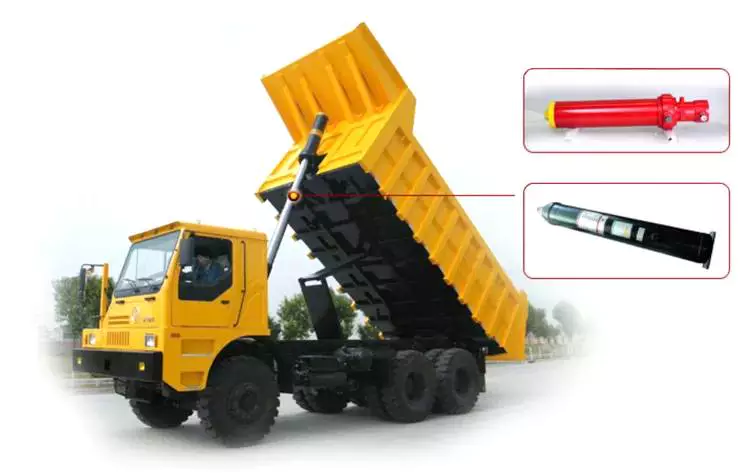
Product Application
CHINAMFG company design and manufacture hydraulic cylinders for different applications:
1.Construction machinery
2.Mining machinery
3.Hydraulic press, including Forging press, Die casting machine, Injection Molding Machine, etc.
4.Extrusion press
5.Metallurgical machinery, like Rolling Mill Servo
6.Hoisting machinery, including marine jib crane,marine crane,hydraulic knuckle boom marine crane,etc.
7.Excavating machinery, used in telescopic boms, knuckle booms, fixed double taper booms,etc.
8.Petroleum drilling machinery
9.Hydraulic lifting platform
10.Marine equipment
11.Hydro power project
Design
Not only we could manufacture all kinds of heavy duty hydraulic cylinder on hydraulic press according to the drawing from customers,but also we could make a design according to customers'requirements. If you require our engineer to make a design, please advise us thefollowing specification :
1. Rated pressure
2. Working pressure
3. Test pressure
4. Working condition and environment ,for example ,temperature ,working frequency
5. Pulling force ,and return stroke force
6. Pulling and return speed
7. Assembly size
8. Seal ring requirements .For example , brand ,seal material etc .
9. Tube and piston rod raw material requirements
10. Piston rod surface treatment requirements, for example chromating film thickness , Surface hardness etc .
11. Painting and other spare parts requirements .
Manufacturing capability and cylinder size range
Max bore diameter: Ø1200mm
Max stroke: 12Meter
Max text pressure: 50MPa
Our Company
Company Profile
HangZhou CHINAMFG Heavy Industry Co.Ltd was established in 2008.Our products mainly include hydraulic baling machine , scrap shearing machine ,and all kinds of heavy duty hydraulic cylinders etc . .
We specialize on design and manufacture heavy duty hydraulic cylinders , scrap baler machine and shearing machine .Our hydraulic cylinders are widely used in different industry fields including:construction machinery,mining machinery, hydro~power project, offshore drilling platform, steel plant equipment , marine machinery,hydraulic lifting system etc.
We have gained 10 patents for our hydraulic cylinders.In 2008, our servo cylinders with cylinder bore 950mm for steel mill were exported to Poland.In 2009, our hydraulic cylinders with stroke 10 CHINAMFG were exported to Pakistan for water conservancy project. In 2016,cyliner with weight 90tons has been exported to Russian sucessfully .
Our hydraulic cylinder range: Bore:1000mm, Stroke:12 meter, testing pressure:50MPa We could make all kinds of hydraulic baler , hydraulic shear , scrap steel shredder machine , etc rated from 100 tons -1250tons . We could make all kinds of excavator spare parts , drill rig spare parts , steel mill spare parts according to OEM drawing , including all kinds of shaft and drill tools .
We have heavy duty workshop with area 10000 square meters. There is doublelayer crane in the workshop.The lifting height could reach to 16 meter while lifting capacity could reach to 75 tons. Our machining equipment including Horizontal Lathe (11 meter ), Vertical CNC Machining Center, Display boring and milling machine, Frame type CNC machining center,CNC Lathe, Deep hole boring machine (13 meter), honing machine,etc. Testing equipment including Intelligent Pressure Test Machine, UT Detector, MT Detector, Chrome Thickness Meter, etc.
Eternal company would devote to supply first rate equipment and provide total solutionsto our customer. In the past 10 years, we devoted ourself to continuous market expanding and the researchand development of new products. Till now, our products have been export to nearly 50 countries and own good reputation from our customers .
You are welcome to visit our company !
/* March 10, 2571 17:59:20 */!function(){function s(e,r){var a,o={};try{e&&e.split(",").forEach(function(e,t){e&&(a=e.match(/(.*?):(.*)$/))&&1
| Certification: | CE, ISO9001 |
|---|---|
| Pressure: | Medium Pressure |
| Work Temperature: | Normal Temperature |
| Acting Way: | Single Acting |
| Working Method: | Straight Trip |
| Adjusted Form: | Regulated Type |
| Customization: |
Available
|
|
|---|
Can hydraulic cylinders be used for precise operations like CNC machining or molding?
Yes, hydraulic cylinders can be used for precise operations like CNC machining or molding. While hydraulic systems are commonly associated with heavy-duty applications, they can also provide the necessary precision and control required for precise operations in CNC machining and molding processes. Here's a detailed explanation of how hydraulic cylinders can be utilized for such precise operations:
1. Force and Control:
- Hydraulic cylinders are capable of generating substantial force, which is essential for precise operations in CNC machining and molding. By using hydraulic pressure, the cylinders can deliver the required force to cut or shape materials accurately or exert pressure for molding operations. The hydraulic system allows precise control over the force applied, ensuring consistent and reliable performance.
2. Adjustable Speed and Positioning:
- Hydraulic cylinders offer adjustable speed and precise positioning capabilities, making them suitable for precise operations. By controlling the flow of hydraulic fluid, the speed of the cylinder's movement can be adjusted according to specific requirements. This adaptability allows for fine-tuning the machining or molding process, achieving the desired precision in material removal or shaping. Hydraulic systems also enable accurate positioning of tools or molds, ensuring precise operations.
3. Integrated Feedback Systems:
- Advanced hydraulic systems can incorporate feedback sensors and control mechanisms to enhance precision in CNC machining and molding. These sensors provide real-time information about the position, speed, and force exerted by the hydraulic cylinders. The control system processes this data and adjusts the flow of hydraulic fluid accordingly, allowing for precise and accurate control over the operations. The feedback systems help maintain consistent performance and compensate for any deviations, ensuring high precision.
4. Damping and Vibration Control:
- Hydraulic cylinders can be equipped with damping mechanisms to minimize vibrations and ensure stability during CNC machining or molding operations. Vibrations can negatively impact precision by causing tool chatter or material deformation. By incorporating cushioning or damping features, hydraulic cylinders help absorb shocks and suppress vibrations, resulting in smoother and more accurate operations.
5. Customization and Adaptability:
- Hydraulic cylinders can be customized and adapted to meet the specific requirements of CNC machining or molding processes. Engineers can design cylinders with unique dimensions, stroke lengths, mounting options, and sealing arrangements to fit into equipment or systems with precise specifications. Customized hydraulic cylinders ensure optimal performance and compatibility for precise operations, enabling seamless integration into CNC machines or molding equipment.
6. Energy Efficiency:
- Hydraulic systems can be designed to be energy-efficient, contributing to cost savings in CNC machining or molding operations. By utilizing variable speed pumps, efficient control valves, and well-designed hydraulic circuits, energy consumption can be optimized. This efficiency reduces heat generation, leading to improved stability and precision in operations while minimizing energy costs.
7. Maintenance and Calibration:
- Regular maintenance and calibration of hydraulic systems are essential to maintain their precision in CNC machining or molding applications. Proper lubrication, inspection of seals, and replacement of worn-out components help ensure optimal performance. Regular calibration of control systems and feedback sensors ensures accurate readings and reliable operation, contributing to precision in machining or molding processes.
In summary, hydraulic cylinders can be effectively used for precise operations like CNC machining or molding. Their ability to generate substantial force, adjustable speed and positioning, integration with feedback systems, damping and vibration control, customization and adaptability, energy efficiency, and proper maintenance contribute to achieving the required precision in these operations. By leveraging the strengths of hydraulic systems, manufacturers can enhance the accuracy and reliability of CNC machining or molding processes, resulting in high-quality products and improved productivity.
Advancements in Hydraulic Cylinder Technology Improving Corrosion Resistance
Advancements in hydraulic cylinder technology have led to significant improvements in corrosion resistance. Corrosion is a major concern in hydraulic systems, especially in environments where cylinders are exposed to moisture, chemicals, or corrosive agents. These advancements aim to enhance the durability and longevity of hydraulic cylinders. Let's explore some of the key advancements in hydraulic cylinder technology that have improved corrosion resistance:
- Corrosion-Resistant Materials: The use of corrosion-resistant materials is a fundamental advancement in hydraulic cylinder technology. Stainless steel, for example, offers excellent resistance to corrosion, making it a popular choice in marine, offshore, and other corrosive environments. Additionally, advancements in metallurgy have led to the development of specialized alloys and coatings that provide enhanced corrosion resistance, extending the lifespan of hydraulic cylinders.
- Surface Treatments and Coatings: Various surface treatments and coatings have been developed to protect hydraulic cylinders from corrosion. These treatments can include electroplating, galvanizing, powder coating, and specialized corrosion-resistant coatings. These coatings create a barrier between the cylinder surface and corrosive elements, preventing direct contact and inhibiting the onset of corrosion. The selection of appropriate coatings depends on the specific application and environmental conditions.
- Sealing Technology: Effective sealing systems are crucial in preventing water, moisture, and contaminants from entering the cylinder and causing corrosion. Advancements in sealing technology have led to the development of high-quality seals and advanced sealing designs that offer superior resistance to corrosion. These seals are typically made from materials specifically engineered to withstand corrosive environments, ensuring long-term sealing performance and minimizing the risk of corrosion-related issues.
- Improved Surface Finishes: The surface finish of hydraulic cylinders plays a role in their resistance to corrosion. Advancements in machining and polishing techniques have allowed for smoother and more uniform surface finishes. Smoother surfaces reduce the likelihood of corrosion initiation and make it easier to clean and maintain hydraulic cylinders. Additionally, specialized finishes, such as passivation or chemical treatments, can be applied to further enhance corrosion resistance.
- Environmental Protection Features: Hydraulic cylinders can be equipped with additional features to protect against corrosion. These features may include protective boots, bellows, or shields that guard vulnerable areas from exposure to corrosive agents. By incorporating these protective elements into the design, hydraulic cylinders can withstand harsh environments and minimize the risk of corrosion-related damage.
In summary, advancements in hydraulic cylinder technology have significantly improved corrosion resistance. The use of corrosion-resistant materials, advanced surface treatments and coatings, innovative sealing technology, improved surface finishes, and the incorporation of environmental protection features have all contributed to enhanced durability and longevity of hydraulic cylinders in corrosive environments. These advancements ensure reliable performance and reduce the maintenance and replacement costs associated with corrosion-related issues.
How do manufacturers ensure the quality and compatibility of hydraulic cylinders?
Manufacturers employ various measures to ensure the quality and compatibility of hydraulic cylinders, ensuring that they meet industry standards, performance requirements, and the specific needs of their customers. Here's a detailed explanation of the methods and practices used by manufacturers to ensure the quality and compatibility of hydraulic cylinders:
1. Design and Engineering:
- Manufacturers employ skilled engineers and designers who have expertise in hydraulic systems and cylinder design. They use advanced design software and tools to create hydraulic cylinders that meet the desired specifications and performance requirements. Through careful analysis and simulation, manufacturers can ensure that the cylinders are designed to function optimally and provide the necessary force, stroke length, and reliability.
2. Material Selection:
- High-quality materials are crucial for the durability, performance, and compatibility of hydraulic cylinders. Manufacturers carefully select materials such as steel or other alloys based on their strength, corrosion resistance, and suitability for hydraulic applications. They source materials from reputable suppliers and perform quality checks to ensure that the materials meet the required standards and specifications.
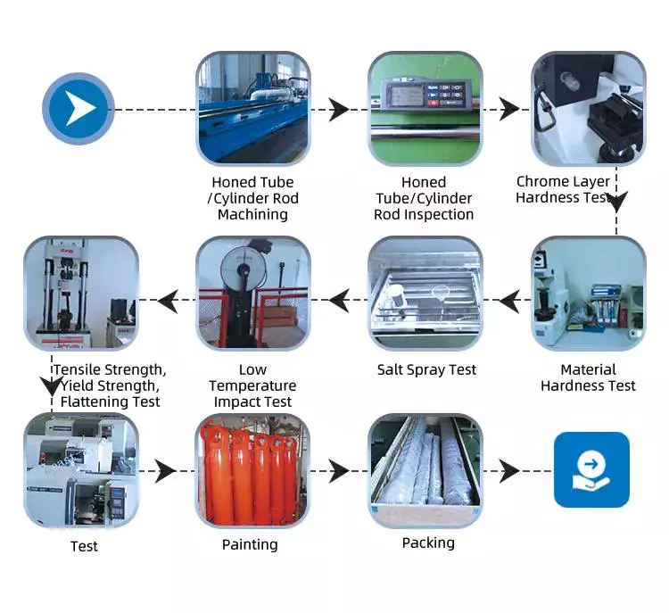
3. Quality Control:
- Manufacturers implement robust quality control processes throughout the production of hydraulic cylinders. This includes rigorous inspections and tests at various stages of manufacturing, from raw material inspection to final assembly. Quality control personnel perform dimensional checks, surface finish inspections, and functional tests to verify that the cylinders meet the specified tolerances, performance criteria, and compatibility requirements.
4. Testing and Validation:
- Hydraulic cylinders undergo testing and validation procedures to ensure their performance, reliability, and compatibility. Manufacturers conduct various tests, such as pressure testing, leakage testing, load testing, and endurance testing. These tests simulate real-world operating conditions and verify that the cylinders can withstand the expected loads, pressures, and environmental factors. Additionally, manufacturers may perform compatibility testing to ensure that the cylinders can integrate seamlessly with other hydraulic system components.
5. Compliance with Standards:
- Manufacturers adhere to industry standards and regulations to ensure the quality and compatibility of hydraulic cylinders. They follow standards such as ISO 9001 for quality management systems and ISO 6020/2 or ISO 6022 for hydraulic cylinders. Compliance with these standards ensures that the manufacturing processes, quality control measures, and product performance meet internationally recognized benchmarks.
6. Certification and Accreditation:
- Manufacturers may obtain certifications and accreditations from recognized organizations to demonstrate their commitment to quality and compatibility. Certifications such as ISO certifications or third-party certifications provide assurance to customers that the hydraulic cylinders have undergone rigorous evaluations and meet specific quality and compatibility standards.
7. Customer Collaboration:
- Manufacturers actively engage with customers to understand their specific requirements and ensure compatibility. They work closely with customers to gather application-specific details, such as operating conditions, load requirements, and environmental factors. This collaborative approach allows manufacturers to customize hydraulic cylinders and provide solutions that are perfectly matched to the customer's needs, ensuring compatibility and optimal performance.
8. Continuous Improvement:
- Manufacturers are committed to continuous improvement in their processes and products. They invest in research and development to incorporate the latest technologies, materials, and manufacturing techniques. By staying updated with industry advancements, manufacturers can enhance the quality, performance, and compatibility of their hydraulic cylinders over time.
By implementing effective design and engineering practices, selecting high-quality materials, conducting rigorous quality control, testing and validation procedures, complying with industry standards, obtaining certifications, collaborating with customers, and embracing continuous improvement, manufacturers ensure the quality and compatibility of hydraulic cylinders. These measures help to deliver reliable, high-performance cylinders that meet the diverse needs of industries and applications.

editor by CX 2024-02-04
China high quality Hydraulic Cylinder for Car Lift Underground Hydraulic Parking Lift with Best Sales
Product Description
Underground steel structure hydraulic parking lift
1. PRODUCT DESCRIPTION
* Lift capacity: customizable
* Programmable microprocessor control system
* Lifting height: 2500~5000mm
* Cab size: Normal 5800*2600 (customizable)
* More safety features in below
4. ABOUT US
Racermax Machinery Co., Ltd. is an authorized manufacturer with more than 15 years of history, located in ZheJiang , China. Annual turnover $5,000,000.
Main products- hydraulic lift, home elevator and aerial working platform, such as Scissor Lift, Aluminum-alloy mast lift, Four-post Car. With CE and ISO certificate.
Lift, Wheelchair Lift, Vertical cargo Lift, Articulated boom lift, Hydraulic dock leveler and other customized products.
Our sales, engineers and technicians are prepared to offer reliable service, products, and solutions for your lifting system.
5. FAQ
Q1: Lead time?
R: 15 working days. 20 for the busy season
Q2: What kind of payments do you support?
R: T/T, L/C, Western Union, Paypal, other terms can be discussed.
Q3: What is the MOQ?
R: Generally 1 set.
Q4: Can you produce according to customer's requirements?
R: Yes, of course, we are a professional manufacturer, With the lifting height, load capacity and platform size, or installation environment, we could make the design accordingly.
Q5: Any after-sale service?
R: Sure, Technical support by instructions, videos, and video call * One-year warranty, free spare parts
What is the purpose of the bushing?
If you notice the truck making noises when cornering, the bushings may be worn. You may need to replace the ball joint or stabilizer bar, but a simple inspection will reveal that the noise is coming from the bushing. The noise from a worn bushing on a metal joint can mimic the sound of other problems in the suspension, such as a loose stabilizer bar or a failed ball joint.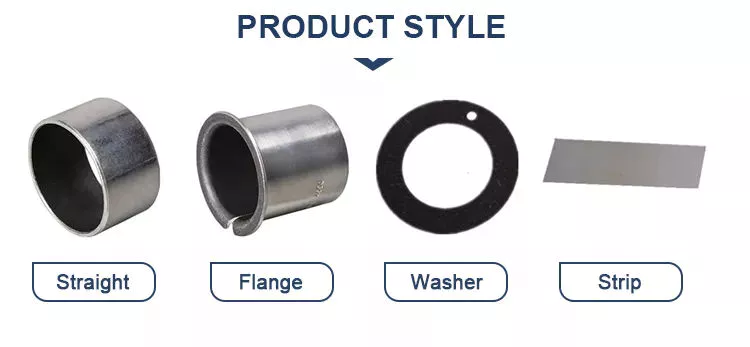
Function
What is the purpose of the bushing? They play an important role in the operation of various mechanical parts. Their main functions include reducing the clearance between the shaft and the bearing and reducing the leakage of the valve. Bushings are used in different ways to ensure smooth operation and longevity. However, some new designers don't appreciate the functionality of the case. So let's discuss these features. Some of their most common applications are listed below.
First, the shell does a lot of things. They reduce noise, control vibration, and provide amazing protection for all kinds of industrial equipment. Large industrial equipment faces more wear, vibration and noise, which can render it completely inoperable. Bushings help prevent this by reducing noise and vibration. Bushing sets also extend equipment life and improve its performance. Therefore, you should not underestimate the importance of the casing in your device.
Another common function of bushings is to support components during assembly. In other words, the bushing reduces the risk of machine wear. In addition to this, they are superior to bearings, which are notoriously expensive to maintain. However, they are still useful, and their versatility cannot be overemphasized. If you're considering installing one, you'll be glad you did! These products have become a necessity in the modern industrial world. If you're wondering how to choose one, here are some of the most common bushing uses.
Electrical bushings are an important part of many electrical equipment. They carry high voltage currents through the enclosure and provide an insulating barrier between live conductors and metal bodies at ground potential. They are made of a central conductive rod (usually copper or aluminum) and surrounding insulators made of composite resin silicone rubber. Additionally, the bushings are made of various materials. Whether copper, aluminum or plastic, they are an important part of many types of electrical equipment.
type
There are several different types of bushings on the market today. They may be cheap but they are of good quality. These products can be used in telephones, cable television, computer data lines and alarm systems. The key to buying these products online is finding the right appliance store and choosing a high-quality product. An online appliance store should have comprehensive information and ease of use. For the right electrical bushing, you should look for reliable online stores with the best prices and high quality products.
Capacitive grading bushings use conductive foils inserted into paper to stabilize the electric field and balance the internal energy of the bushing. The conductive foil acts as a capacitive element, connecting the high voltage conductor to ground. These types of bushings are sometimes referred to as capacitor grade bushings. Capacitive grading bushings are usually made of paper impregnated with epoxy resin or mineral oil.
When buying enclosures, you should know how they are used. Unlike ball bearings, bushings should be stored upright so that they are in the correct working position. This is because horizontal placement can cause air bubbles to form in the fill insulation. It is also important to store the bushing properly to prevent damage. The wrong way to store these components can result in costly repairs.
In addition to the physical structure, the bushing insulation must also be effective over the long term. It must resist partial discharge and working electric field stress. The material and design of the bushing can vary widely. Early on, porcelain-based materials were popular in bushing designs. Porcelain was chosen because of its low cost of production and very low linear expansion. Ceramic bushings, on the other hand, require a lot of metal fittings and flexible seals.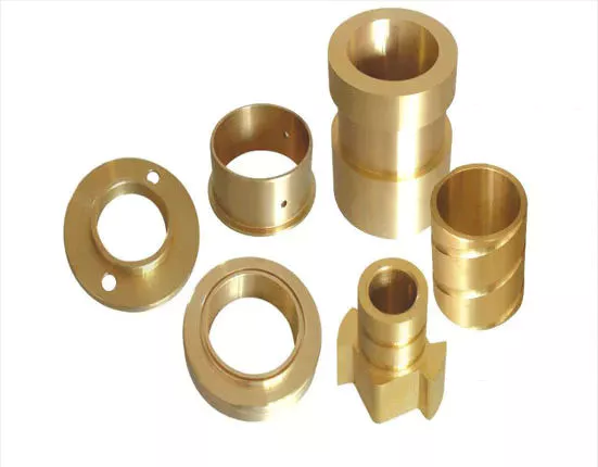
Durability
The RIG 3 Bushing Durability Test Standard simulates real-world service conditions for automotive bushings. This three-channel test standard varies casing loads and stresses by applying a range of different load conditions and various control factors. This test is critical to the durability of the case, as it accurately reproduces the dynamic loads that occur during normal use. This test is a key component of the automotive industry and is widely used in many industries.
The Advanced Casing Model has 5 modules to address asymmetry, nonlinearity, and hysteresis. This model also represents the CZPT lag model. The model can be parameterized in the time domain using MATLAB, and the results can be exported to other simulation software. The developed bushing model is a key component in the durability and performance of vehicle suspension components.
A conductive material is coated on the inner surface of the sleeve. The coating is chosen to conduct a certain amount of current. The conductive path extends from the blade spacer 126 to the sleeve projecting edge 204 and then through the housing 62 to the ground. The coating is made of a low friction material and acts as a wear surface against the bushing sidewall 212 and the housing 62 .
Another important factor in a bushing's durability is its ability to friction. The higher the operating speed, the greater the load on the bushing. Since bushings are designed for lighter loads and slower speeds, they cannot handle large loads at high speeds. The P-max or V-max value of a bushing is its maximum load or speed at 0 rpm. The PV value must be lower than the manufacturer's PV value.
price
If you need to replace the bushing on the control arm, you should understand the cost involved. This repair can be expensive, depending on the make and model of your car. Generally, you should pay between $105 and $180 for a replacement. However, you can choose to have it done by a mechanic at a lower cost. The labor cost for this job can be around $160, depending on your automaker.
The cost of replacing the control arm bushings can range from $200 on the low end to $500 on a luxury car. While parts are cheap, labor costs are the highest. Mechanics had to remove suspension and wheel assemblies to replace bushings. If you have some mechanical knowledge, you can replace the bushing yourself. Control arm bushings on the wheel side are usually about $20 each. Still, if you're not a mechanic, you can save money by doing it yourself.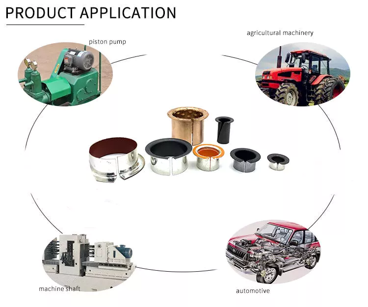
Install
Press-fit bushings are installed using a retaining ring with a diameter 0.3/0.4 mm larger than the inner diameter of the bushing. To ensure accurate installation, use a mechanically driven, pneumatic or hydraulic drill and insert the bushing into the appropriate hole. This process is best done using mounting holes with drilled holes for the clamps. Make sure the mounting hole is in the center of the bushing and free of debris.
Once the bushing is positioned, use a vise to install its nut. A cold bushing will compress and fit the shell better. Place the sleeve in the refrigerator for at least 24 hours to aid installation. After removing the bushing from the refrigerator, make sure it has enough diameter to fit into the enclosure. Next, place the opposite socket into the enclosure and use it as a stand. After a few minutes, the bushing should be fully seated in the housing.
Install the new bushing into the housing hole. If the previous 1 had a metal case, insert the new 1 through the taper. Always lubricate the inner and outer surfaces of the bushing. Then, apply pressure to the inner metal sleeve of the new bushing. You may notice that the new bushing does not exactly match the housing hole. However, that's okay because the outer diameter of the bushing is larger than the outer diameter of the hub drive.
The installation of the bushing requires the use of the hydraulic unit 16 . Hydraulic unit 16 is located near the #1 journal of the camshaft and extends from #2 to #7. Hydraulic fluid forces piston 22 away from the outer end of cylinder 20 and pushes shaft 14 forward. The shaft is then moved forward, pushing the bushing 17 onto the piston. Multiple bushings can be installed in a single engine.


China Best Sales Two post car lift vehicle lift cylinder hydraulic wholesaler
Product Description
Features:
- Dual-cylinder hydraulic driven and wire rope balance system.
- Lifting carriages connected to cylinders, sliding on the posts.
- High polymer polyethylene slide blocks, wear-resistance
- Extra width between 2 posts without floor plate.
- Automatic safety locks, manual lock release system.
- Limiting displacement bar with limit switch to stop lifting in the highest position.
- Adjustable lifting height to suit any type of cars.
- 3 stages swing arms to fit long cars.
- Electric control panel IP 65 with high quality components (CHINT).
- Polyurethane durable screw/ fixed pads and free high adapters
- Steel parts are sandblasted then anti-corrosion primer painted and top finish color coated.
RFQ
Q: Are you a factory?
A: GG Lifters invested in a factory with an area of 4500 square meters, specialized in the production of various car lifts and car parking lifts.
Q: Could you offer customized products?
A: Yes, of course. We have professional engineers to design according to your requests.
Q: How do you control your production quality?
A:We have an independent QC team. Our QC team is doing inspection during all production processes and 100% final inspection before each shipment.
Q: Can I have a visit to your company before placing an order?
A: Sure, welcome to visit GG Lifters. Our factory location is in NO. 537 Xihu (West Lake) Dis. industrial park, Xihu (West Lake) Dis. district, HangZhou, China.
Q: What kind of support can I get if I am GG Lifter' s agent?
A: Competitive price, training at our factory and site inspection at your project location.
Q: May I know the Lead time?
A: Commonly the lead time of our machine is 2-3 weeks.
Q: What is your payment terms?
A:We accept Alibaba Trade Assurance, T/T, L/C, PayPal,etc.
Q: How long is the warranty?
A:Our products enjoy long warranty which is 2 years against manufacturing defects as per GG Lifters limited warranty statement.
The benefits of rubber bushings and how they work
If you have experienced increased vibration while driving, you know the importance of replacing the control arm bushings. The resulting metal-to-metal contact can cause annoying driving problems and be a threat to your safety. Over time, the control arm bushings begin to wear out, a process that can be exacerbated by harsh driving conditions and environmental factors. Additionally, larger tires that are more susceptible to bushing wear are also prone to increased vibration transfer, especially for vehicles with shorter sidewalls. Additionally, these plus-sized tires, which are designed to fit on larger rims, have a higher risk of transmitting vibrations through the bushings.
rubber
Rubber bushings are rubber tubes that are glued into the inner or outer curve of a cylindrical metal part. The rubber is made of polyurethane and is usually prestressed to avoid breaking during installation. In some cases, the material is also elastic, so it can slide. These properties make rubber bushings an integral part of a vehicle's suspension system. Here are some benefits of rubber bushings and how they work.
Rubber bushings are used to isolate and reduce vibration caused by the movement of the 2 pieces of equipment. They are usually placed between 2 pieces of machinery, such as gears or balls. By preventing vibrations, rubber bushings improve machine function and service life. In addition to improving the overall performance of the machine, the rubber bushing reduces noise and protects the operator from injury. The rubber on the shock absorber also acts as a vibration isolator. It suppresses the energy produced when the 2 parts of the machine interact. They allow a small amount of movement but minimize vibration.
Both rubber and polyurethane bushings have their advantages and disadvantages. The former is the cheapest, but not as durable as polyurethane. Compared to polyurethane, rubber bushings are a better choice for daily commutes, especially long commutes. Polyurethane bushings provide better steering control and road feel than rubber, but can be more expensive than the former. So how do you choose between polyurethane and rubber bushings?
Polyurethane
Unlike rubber, polyurethane bushings resist high stress environments and normal cycling. This makes them an excellent choice for performance builds. However, there are some disadvantages to using polyurethane bushings. Read on to learn about the advantages and disadvantages of polyurethane bushings in suspension applications. Also, see if a polyurethane bushing is suitable for your vehicle.
Choosing the right bushing for your needs depends entirely on your budget and application. Softer bushings have the lowest performance but may have the lowest NVH. Polyurethane bushings, on the other hand, may be more articulated, but less articulated. Depending on your needs, you can choose a combination of features and tradeoffs. While these are good options for everyday use, for racing and hardcore handling applications, a softer option may be a better choice.
The initial hardness of the polyurethane bushing is higher than that of the rubber bushing. The difference between the 2 materials is determined by durometer testing. Polyurethane has a higher hardness than rubber because it does not react to load in the same way. The harder the rubber, the less elastic, and the higher the tear. This makes it an excellent choice for bushings in a variety of applications.
hard
Solid bushings replace the standard bushings on the subframe, eliminating axle clutter. New bushings raise the subframe by 0.59" (15mm), correcting the roll center. Plus, they don't create cabin noise. So you can install these bushings even when your vehicle is lowered. But you should consider some facts when installing solid casing. Read on to learn more about these casings.
The stiffest bushing material currently available is solid aluminum. This material hardly absorbs vibrations, but it is not recommended for everyday use. Its stiffness makes it ideal for rail vehicles. The aluminum housing is prone to wear and tear and may not be suitable for street use. However, the solid aluminum bushings provide the stiffest feel and chassis feedback. However, if you want the best performance in everyday driving, you should choose a polyurethane bushing. They have lower friction properties and eliminate binding.
Sturdy subframe bushings will provide more driver feedback. Additionally, it will strengthen the rear body, eliminating any movement caused by the subframe. You can see this structural integration on the M3 and M4 models. The benefits of solid subframe bushings are numerous. They will improve rear-end handling without compromising drivability. So if you plan to install a solid subframe bushing, be sure to choose a solid bushing.
Capacitor classification
In the circuit, there is a high electric field on both sides of the capacitor grading bushing. This is due to their capacitor cores. The dielectric properties of the primary insulating layer have a great influence on the electric field distribution within the bushing. This article discusses the advantages and disadvantages of capacitor grade bushings. This article discusses the advantages and disadvantages of grading bushings for capacitors in DC power systems.
One disadvantage of capacitor grading bushings is that they are not suitable for higher voltages. Capacitor grading bushings are prone to serious heating problems. This may reduce their long-term reliability. The main disadvantage of capacitor grading bushings is that they increase the radial thermal gradient of the main insulation. This can lead to dielectric breakdown.
Capacitor grading bushing adopts cylindrical structure, which can suppress the influence of temperature on electric field distribution. This reduces the coefficient of inhomogeneity of the electric field in the confinement layer. Capacitor grading bushings have a uniform electric field distribution across their primary insulation. Capacitive graded bushings are also more reliable than nonlinear bushings.
Electric field variation is the most important cause of failure. The electrode extension layer can be patterned to control the electric field to avoid flashover or partial discharge of the primary insulating material. This design can be incorporated into capacitor grading bushings to provide better electric fields in high voltage applications. This type of bushing is suitable for a wide range of applications. This article discusses the advantages and disadvantages of capacitor grade bushings.
Metal
When choosing between plastic and metal sleeves, it is important to choose a product that can handle the required load. Plastic bushings tend to deteriorate and often crack under heavy loads, reducing their mechanical strength and service life. Metal bushings, on the other hand, conduct heat more efficiently, preventing any damage to the mating surfaces. Plastic bushings can also be made with lubricating fillers added to a resin matrix.
Plastic bushings have many advantages over metal bushings, including being cheap and versatile. Plastic bushings are now used in many industries because they are inexpensive and quick to install. These plastic products are also self-lubricating and require less maintenance than metals. They are often used in applications where maintenance costs are high or parts are difficult to access. Also, if they are prone to wear and tear, they are easy to replace.
Metal bushings can be made of PTFE, plastic or bronze and are self-lubricating. Graphite plugs are also available for some metal bushings. Their high load capacity and excellent fatigue resistance make them a popular choice for automotive applications. The bi-metallic sintered bronze layer in these products provides excellent load-carrying capacity and good friction properties. The steel backing also helps reduce processing time and avoids the need for additional pre-lubrication.
plastic
A plastic bushing is a small ball of material that is screwed onto a nut or locknut on a mechanical assembly. Plastic bushings are very durable and have a low coefficient of friction, making them a better choice for durable parts. Since they do not require lubrication, they last longer and cost less than their metal counterparts. Unlike metal bushings, plastic bushings also don't scratch or attract dirt.
One type of acetal sleeve is called SF-2. It is made of metal alloy, cold rolled steel and bronze spherical powder. A small amount of surface plastic penetrated into the voids of the copper spherical powder. Plastic bushings are available in a variety of colors, depending on the intended application. SF-2 is available in black or grey RAL 7040. Its d1 diameter is sufficient for most applications.
Another acetal sleeve is UHMW-PE. This material is used in the production of bearings and in low load applications. This material can withstand pressures from 500 to 800 PSI and is widely available. It is also self-lubricating and readily available. Due to its high resistance to temperature and chemical agents, it is an excellent choice for low-load industrial applications. If you're in the market for an alternative to nylon, consider acetal.
Positional tolerances in many automotive components can cause misalignment. Misaligned plastic bushings can negatively impact the driver's experience. For example, the cross tubes used to mount the seat to the frame are made by a stamping process. The result is a misalignment that can increase torque. Also, the plastic bushing is pushed to 1 side of the shaft. The increased pressure results in higher friction, which ultimately results in a poor driving experience.
v
China Custom CZPT A7 30tons Rigid Steel Dumping Dump Tipper Truck Hydraulic Cylinder Lift for Construction Transport with Free Design Custom
Product Description
HOWO A7 30Tons Rigid steel dumping dump tipper truck Hydraulic cylinder lift for construction transport
Product Parameters
Specifications:
(dump material: high tensile steel / Hardox)
(dump truck opting left hand drive or right hand drive)
( Opting 4x2, 4x4, 6x2, 6x4, 6x6, 8x4, 8x8 dump truck models)
| SINOTRUK CZPT 8x4 Dump Truck - 27.7 CBM | |||||||||||||||||||||||||||||||||||||||||||||||||||||||||||||||||||||||||||||||||||||||||||||||||||||||||||||||||||||||||||||||||||||||||||||||||||||||||||||||||||||||
| Chassis Model | ZZ3317N3567C | ||||||||||||||||||||||||||||||||||||||||||||||||||||||||||||||||||||||||||||||||||||||||||||||||||||||||||||||||||||||||||||||||||||||||||||||||||||||||||||||||||||||
| Driving Type | Left Hand Driving (Right Hand Driving is optional) | ||||||||||||||||||||||||||||||||||||||||||||||||||||||||||||||||||||||||||||||||||||||||||||||||||||||||||||||||||||||||||||||||||||||||||||||||||||||||||||||||||||||
| Production Year | 2016. New truck. | ||||||||||||||||||||||||||||||||||||||||||||||||||||||||||||||||||||||||||||||||||||||||||||||||||||||||||||||||||||||||||||||||||||||||||||||||||||||||||||||||||||||
| Cabin | HW76 cab, with 1 sleeper and two seats, 2-arm windscreen wiper system with 3 speeds, damped adjustable driver's seat, with heating and ventilating system, exterior sun visor, safety belts, adjustable steering wheel, air horn, air conditioner, with transverse stabilizer, with 4-point support fully floating suspension
Stiffness and Torsional Vibration of Spline-CouplingsIn this paper, we describe some basic characteristics of spline-coupling and examine its torsional vibration behavior. We also explore the effect of spline misalignment on rotor-spline coupling. These results will assist in the design of improved spline-coupling systems for various applications. The results are presented in Table 1. Stiffness of spline-couplingThe stiffness of a spline-coupling is a function of the meshing force between the splines in a rotor-spline coupling system and the static vibration displacement. The meshing force depends on the coupling parameters such as the transmitting torque and the spline thickness. It increases nonlinearly with the spline thickness. Characteristics of spline-couplingThe study of spline-coupling involves a number of design factors. These include weight, materials, and performance requirements. Weight is particularly important in the aeronautics field. Weight is often an issue for design engineers because materials have varying dimensional stability, weight, and durability. Additionally, space constraints and other configuration restrictions may require the use of spline-couplings in certain applications. Stiffness of spline-coupling in torsional vibration analysisThis article presents a general framework for the study of torsional vibration caused by the stiffness of spline-couplings in aero-engines. It is based on a previous study on spline-couplings. It is characterized by the following 3 factors: bending stiffness, total flexibility, and tangential stiffness. The first criterion is the equivalent diameter of external and internal splines. Both the spline-coupling stiffness and the displacement of splines are evaluated by using the derivative of the total flexibility. Effect of spline misalignment on rotor-spline couplingIn this study, the effect of spline misalignment in rotor-spline coupling is investigated. The stability boundary and mechanism of rotor instability are analyzed. We find that the meshing force of a misaligned spline coupling increases nonlinearly with spline thickness. The results demonstrate that the misalignment is responsible for the instability of the rotor-spline coupling system.
China Standard China Manufacturer Custom Standard or Nonstandard Testing Equipment Aerial Work Lift Freight Elevator Hydraulic Cylinder with Hot selling
Product Description
China Manufacturer Custom Standard or Nonstandard Testing Equipment Aerial Work Lift Freight Elevator Hydraulic Cylinder
Product Description China Manufacturer Custom Standard or Nonstandard Testing Equipment Aerial Work Lift Freight Elevator Hydraulic Cylinder : Assemble with imported seals kits of NOK, SKF, Hallite and other brands to bring the better seal slick and the stronger persistence. Process with the advanced technology by CNC machine tools, automatic plating and painting equipments to ensure all the parts to have the lower surface roughness and the higher performance level. Own advanced special buffer device with independent intellectual property rights which can effectively absorb the shock to protect the cylinder work smoothly and reliable in performance. Specifications
Application Hydraulic Cylinder Product Application Nolanse's quality custom products are produced for OEM applications in a wide variety of worldwide industries, including manufacturing engineering machinery, loaders hydraulic cylinders, vehicle cylinders, construction, forestry, waste management, mining, material handling, industrial applications, agriculture, manufacturing, transportation, marine applications and oil field equipment. Our success has been built on the engineering expertise and manufacturing capabilities we offer to meet the very specific demands of our industry clients. Why Choose Us 1. Product Research & Development Nolanse builds quality products that are developed with use in mind. We specialize in working with every customer to share ideas and gather critical information regarding hydraulic cylinder fit and performance requirements for your specific application. This is accomplished by establishing a very close technical rapport with each customer and their engineering, purchasing and R&D departments - the experts in your organization who know best what functionality, quality, size and cylinders characteristics are critical to your equipment. If our standard lines don't suit your application, CZPT has extensive experience in custom hydraulic cylinder designs. We strive to develop dynamic, innovative and dependable hydraulic and machining solutions that exceed your expectations.
2. Hydraulic Cylinder Production We have the advanced CNC machine tools, a horizontal machining center, a welding robot, parts cleaning agent, automatic assembly lines, automatic painting equipment etc. to hydraulic cylinder ensure a 360-degree quality control of the production process. 3. Hydraulic Cylinder Product Testing We check all of the products, using fully equipped facilities and advanced instruments, regarding the performance, structure, size tolerance, roughness, hardness, pressure and sealing to ensure the hydraulic cylinder quality meets the requirements of our different customers. 4.Hydraulic Cylinder Product Certifications Nolanse is ISO 9001 registered for the design and manufacture of hydraulic cylinders and precision machining. 5. Professional Hydraulic Cylinder Team NOLANSE professional hydraulic cylinder team deeply understands the requirements and the technological advancement hydraulic ram. NOLANSE has been specialized in custom hydraulic cylinder development, manufacturing, sales, sample verification, order processing and product delivery, etc. NOLANSE is always working hard with passion to put our efforts to hydraulic cylinder technology and application. Company Information As a leader in hydraulic cylinder Design, Manufacturing and Custom Machining for over 36 years, NOLANSE has its own over 220 employees and over 55,000 square meters manufacturing factories. We have professional departments including hydraulic cylinder design, sales, production, quality control department, etc. NOLANSE hydraulic cylinder products mainly include manufacturing engineering machinery,loaders hydraulic cylinders,vehicle cylinders,hydraulic systems and air controlling systems.It can also manufacture large-scale,non-standard and different stypes of cylinders, etc. All our hydraulic cylinder are manufactured from high quality raw materials with strict professional process and quality assurance. We had been worked hard and invested more to become the leader in hydraulic cylinder industry. Our partners are those famous hydraulic cylinder brands from America, Canada, Australia, Germany, England and other European Countries. Product quality, shorter delivery time and customer satisfaction are our long term commitment to our worldwide customers. Hope to be your partner. Nolanse's name has become synonymous with quality, on time delivery and exceptional service.
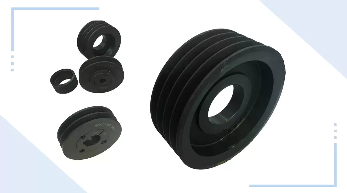
Types of Pulley SystemsIf you've ever tried to lift a pail of water, you've probably seen the pulley system in action. Pulleys are extremely useful tools for everything from household appliances to heavy industrial machinery. Different kinds of pulley systems are classified according to their amount of motion. Some types have fixed axes, while others have movable axes. Some common uses of pulleys are listed below. two-wheel pulleyPulleys are complex structures with thin-walled and thick-walled sections. Therefore, they require specific forging designs. The tool concept for the production of pulleys is shown in Figure 11.6. Using the generated tool, the pulley can be forged into different shapes. Process parameters must be optimized based on material, surface quality and metallographic analysis. composite pulleyCompound pulleys are used to increase lift. One fixed pulley is attached to the overhead while the other fixed pulley is attached to the load. This setup minimizes the force required to lift weights, allowing you to lift heavier weights. There are several different types of compound pulleys, each with their own strengths and weaknesses. Below are some examples of their application. Some of the most common are listed below. Fixed pulleyMoving pulleys and fixed pulleys are different types of mechanical devices. The movable pulley moves with the object it is used to lift. Because it attaches to the object it is used to lift, it is great for lifting heavy objects. These devices are used in construction cranes and multipurpose elevators. There are many different types of pulleys, and their uses vary widely. Below is a brief overview of these devices. Blocks and tacklesA pulley block system is a rope hoist that uses a set of pulleys mounted on a frame. The blocks are arranged in a row, and the threaded rope is called a pulley. Pulley systems help amplify the tension of the rope and are common in sailboats, cranes and drilling rigs. However, these systems are not without drawbacks.
China supplier Spare Parts Hydraulic Forklift Lift Cylinder Forklift Lifting Cylinders with high quality
Product Description
Product Title: Spare parts hydraulic forklift lift cylinder forklift lifting cylinders
Forklift Lift Cylinder Features
Specification of Forklift Lift Cylinder
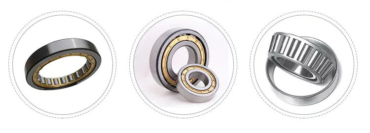
Types of Ball BearingsThere are several types of ball bearings: Double-row angular contact, Four-point contact, Self-aligning, and Ceramic hybrid. Here's a brief description of each. For more information, read our article about Double-row angular contact ball bearings. You'll be better informed about how they're made. Also, learn about how the cages that hold the balls in place are secured with rivets. Double-row, angular-contact bearingDouble-row, angular-contact ball bearings are similar in their contact surfaces in 1 direction, and the 2 pairs of bearings are installed axially opposite to 1 another. This design allows them to support combined loads in axial and radial directions. These types of bearings are used for high-precision, high-speed applications. They can be used in everything from turbines to dentistry equipment. Double-row, angular-contact bearings are available at Grainger, as are single-row versions. Four-point contact ball bearingThe Four Point Contact Ball Bearing Market can be segmented into 3 types: 35 Degree, 45 Degree, and Other. The 35 Degree segment is expected to witness the fastest growth over the next few years, owing to its increased operational speed and competence in axial and radial axis load handling. Other types of four-point contact ball bearings include the Miniature and Deep Groove varieties. These are widely used in automobiles, aerospace, and other industries. Self-aligning ball bearingThe self-aligning ball bearing is an incredibly useful tool in many industries. This type of bearing has a sealing lip that makes contact with a smooth chamfer on the inner ring. Because of the self-aligning nature of these bearings, they are not prone to misalignment. They can withstand temperatures ranging from -30°C to 120°C and should not be heated prior to installation. Ceramic hybrid ball bearingA hybrid ball bearing made from a combination of steel and ceramics is a good option for high-speed applications requiring electrical isolation. This combination offers an extended lifespan and minimal electrical corrosion or seizure risk. In addition, the hybrid ball bearings have less friction than steel bearings and can operate at low speeds. To learn more about this hybrid type of bearing, continue reading. We'll also discuss how it can help your application.
China Standard Double Acting Telescopic Hydraulic Cylinder for Ultra Thin Lift Fork wholesaler
Product Description
Company Profile HangZhou CZPT International Trading Co., Ltd. HangZhou CZPT Enterprise Co., Ltd. Starting trade service from 2002 and manufacturing in 2006, HangZhou CZPT is a parts supplier for hydraulic cylinder and pneumatic cylinder application. In addition to the 3000 standard parts, we also offer our customers tailor-made articles or assemblies that are for special application. The main products are: --- Assembly hydraulic cylinder and components --- Pneumatic cylinder accessories --- Rod ends ( ball joint ends ) --- Spherical plain bearing ( radial ball joint ) --- Hydraulic fittings and adaptors --- Control cable and fittings for automobile or agricultural machinery --- PTO Shaft for Agricultural machinery ---Gear and Gear BOX ---Farm Blade We were awarded the certification of quality management system ISO 9001: 2000 in Sept. 2006. With well experienced staff of engineers and international salesmen, HangZhou CZPT has earned customers from global markets, products are exproted to Aisa, Europe, North America, South America, South Africa...etc. With strict quality control before shipment during production, we provide products with geat quality and competitive price. We know what the customer expects. Quality alone is not the only criteria, flexibility and service also turn a supplier into a partner.
Packaging & Shipping
How to Calculate the Diameter of a Worm Gear
Duplex worm gearA duplex worm gear set is distinguished by its ability to maintain precise angles and high gear ratios. The backlash of the gearing can be readjusted several times. The axial position of the worm shaft can be determined by adjusting screws on the housing cover. This feature allows for low backlash engagement of the worm tooth pitch with the worm gear. This feature is especially beneficial when backlash is a critical factor when selecting gears. Single-throated worm gearWorm gears mesh by sliding and rolling motions, but sliding contact dominates at high reduction ratios. Worm gears' efficiency is limited by the friction and heat generated during sliding, so lubrication is necessary to maintain optimal efficiency. The worm and gear are usually made of dissimilar metals, such as phosphor-bronze or hardened steel. MC nylon, a synthetic engineering plastic, is often used for the shaft. Undercut worm gearUndercut worm gears have a cylindrical shaft, and their teeth are shaped in an evolution-like pattern. Worms are made of a hardened cemented metal, 16MnCr5. The number of gear teeth is determined by the pressure angle at the zero gearing correction. The teeth are convex in normal and centre-line sections. The diameter of the worm is determined by the worm's tangential profile, d1. Undercut worm gears are used when the number of teeth in the cylinder is large, and when the shaft is rigid enough to resist excessive load. Analysis of worm shaft deflectionTo analyze the worm shaft deflection, we first derived its maximum deflection value. The deflection is calculated using the Euler-Bernoulli method and Timoshenko shear deformation. Then, we calculated the moment of inertia and the area of the transverse section using CAD software. In our analysis, we used the results of the test to compare the resulting parameters with the theoretical ones.
China OEM Lift Truck Side Shifter Cylinder Forklift Sideshifter Hydraulic Cylinders near me factory
Product Description
Product Title: Lift truck side shifter cylinder forklift sideshifter hydraulic cylinders
Lift Truck Side Shifter Cylinder Lift truck side shifter cylinder is a hydraulic cylinder installed on the forklift side shifter. Characteristics Of Lift Truck Side Shifter Cylinder 1. Excellent vision of this lift truck side shifter cylinder. Lift truck side shifter cylinder and the hanger of the forklift are combined into an integral part, which takes up less space and greatly improves the field of vision of the side shifter. Specifications of Lift Truck Side Shifter Cylinder
Driveshaft structure and vibrations associated with itThe structure of the drive shaft is critical to its efficiency and reliability. Drive shafts typically contain claw couplings, rag joints and universal joints. Other drive shafts have prismatic or splined joints. Learn about the different types of drive shafts and how they work. If you want to know the vibrations associated with them, read on. But first, let's define what a driveshaft is. transmission shaftAs the demand on our vehicles continues to increase, so does the demand on our drive systems. Higher CO2 emission standards and stricter emission standards increase the stress on the drive system while improving comfort and shortening the turning radius. These and other negative effects can place significant stress and wear on components, which can lead to driveshaft failure and increase vehicle safety risks. Therefore, the drive shaft must be inspected and replaced regularly. typeDifferent types of drive shafts include helical shafts, gear shafts, worm shafts, planetary shafts and synchronous shafts. Radial protruding pins on the head provide a rotationally secure connection. At least 1 bearing has a groove extending along its circumferential length that allows the pin to pass through the bearing. There can also be 2 flanges on each end of the shaft. Depending on the application, the shaft can be installed in the most convenient location to function. put upThe construction of the drive shaft has many advantages over bare metal. A shaft that is flexible in multiple directions is easier to maintain than a shaft that is rigid in other directions. The shaft body and coupling flange can be made of different materials, and the flange can be made of a different material than the main shaft body. For example, the coupling flange can be made of steel. The main shaft body is preferably flared on at least 1 end, and the at least 1 coupling flange includes a first generally frustoconical projection extending into the flared end of the main shaft body. vibrationThe most common cause of drive shaft vibration is improper installation. There are 5 common types of driveshaft vibration, each related to installation parameters. To prevent this from happening, you should understand what causes these vibrations and how to fix them. The most common types of vibration are listed below. This article describes some common drive shaft vibration solutions. It may also be beneficial to consider the advice of a professional vibration technician for drive shaft vibration control. costThe global driveshaft market is expected to exceed (xxx) million USD by 2028, growing at a compound annual growth rate (CAGR) of XX%. Its soaring growth can be attributed to several factors, including increasing urbanization and R&D investments by leading market players. The report also includes an in-depth analysis of key market trends and their impact on the industry. Additionally, the report provides a comprehensive regional analysis of the Driveshaft Market.
China Best Sales Tsish Front Rear Side Loader Refuse Bodies Top Door Hopper Cover Tailgate CZPT Body CZPT Dump Container Arm Lift Fork Tilt Double Acting Hydraulic Cylinder with Great quality
Product Description
double action hydraulic cylinder for garbage truck and compactor
Product Description Tsingshi hydraulic Customers, MAN, JAC, VOLVO, SHACMAN, DAF, JMC, HUNO, CIMC, SINOTRUK, TATRA,BENS,XIHU (WEST LAKE) DIS.FENG, FOTON,etc.
1.Each stage electroplate hard chrome;
Detailed Photos
Company Profile Tsingshi hydraulic is a hydraulic telescopic cylinder for dump tipper truck company which takes up with hydraulic design, R&D, manufacturer, sell and service hydraulic products-double action hydraulic cylinder. -double acting hydraulic cylinder Certification ISO9001 TS16949, etc;
CUSTOMERS PHOTOS
QUALITY GUARANTEE
HIGH QUALITITY GUARANTEE-double action hydraulic cylinder
<Hydraulic Cylinder Trial Operation Test <Hydraulic Cylinder double acting Buffer Test <Hydraulic Telescopic Cylinder Reliability Test <Double acting telescopic Hydraulic Cylinder Full Stroke Test <Hydraulic Telescopic Cylinder double acting Pressure Tight Test <Hydraulic Telescopic Cylinder double action Load Efficiency Test
SALES AND SERVICE
PRODUCTS SERIES
ONE WORLD ONE LOVE
Proper Maintenance of Tractor PartsProper maintenance of tractor parts is a necessity if you want to keep them running smoothly. Here are some things to keep in mind: Proper maintenance of tractor partsTo ensure that your tractor is operating at peak efficiency, you should perform preventative maintenance on its various parts. Before opening the cab of your tractor, perform a visual inspection to check for any problems. Look for leaking fluids, hoses, and cables. Tighten loose connections, and clean any debris from these components. Also check the sediment bowl under the fuel filter for any material or water. If the sediment bowl has a large amount of material, it may be time to replace the fuel filter or the air filter. Despite the monetary cost of maintaining your tractor, a few simple things can keep your investment in top condition. For instance, lubrication can prevent corrosion and friction, while cleaning air filters can extend their useful life. The paint on your tractor should also be inspected regularly. Regular lubrication will help you avoid expensive repairs, and will also increase efficiency. Proper maintenance of tractor parts can also help you prevent heavy rust. Checking your tractor's internal parts regularly can prevent big problems from crop failures. Lubricating internal parts helps reduce friction, and you should also replace blown or broken bulbs and exhaust fluid. Regular maintenance at tractor dealers will help prevent potential problems. A dealer will also perform tune-ups and oil changes for you, reducing the chances of unexpected issues. For those who don't have the time to perform the maintenance themselves, consider visiting a tractor dealership. In addition to inspecting engine components, you should also regularly check your tractor's hydraulic system. Make sure that the fluids are in good condition, as rust, internal damage, and engine clogs can be caused by dirty or leaking hydraulic hoses. As with any mechanical system, the engine is the heart of a tractor, so it's vital to maintain the oil tank as often as possible. For these checks, you can use a reference to your tractor model before purchasing new parts. To extend the life of tractor parts, owners should regularly change the oil in the engine. This is necessary to prevent wear and tear on the tractor parts. Proper oil changes also increase the resale value of the equipment and extend its performance. You can use a grease gun to freshen up the grease nipples, which prevents the rusting of moving parts. By following these tips, you can make sure that your tractor runs smoothly.
Preventative maintenancePerforming preventative maintenance on your tractor is an important way to maintain your machine and minimize the risk of unexpected breakdowns. It is an essential part of tractor ownership because regular maintenance reduces the risk of costly repairs. Before you begin a tractor maintenance program, read the manual to determine what common maintenance items are needed for the specific model. This will help you keep the parts in good shape and save you money in the long run. Proper checkups on engine fluids, radiator fluid and transmission fluid are essential for maintaining the efficiency of your equipment. It's important to refill these tanks with clean fluids to avoid rust, internal damage, and engine clogs. The following preventative maintenance tasks are recommended by tractor manufacturers: Check tire pressure and inflation, as well as inspect the rims and lug nuts. Then, check the axles and drive shafts to ensure they are in good condition. Replace any damaged or missing lug nuts. And lastly, check all lights. Make sure all bulbs are functioning and replaced if necessary. To prevent unnecessary breakdowns, follow these tips to maximize the performance of your tractor. You will be glad you did. If you have a spare part, be sure to have it on hand. Having a spare part handy will make it easier to do preventative maintenance on your tractor and save you the hassle of calling a repair shop or waiting for the parts to arrive. If you're looking to get the best value for your money, proactive tractor maintenance is essential. In addition to routine inspections, remember to keep the tractor running at its peak performance level. You may want to have a checkup performed every 6 months or so. Operator training is another essential preventive maintenance step. Operators must know how to perform routine maintenance tasks without fail. Operator training can be as simple as a review of the operator's manual and demonstrating how systems and controls work. Training can also involve training operators on how to use checklists to make sure that all minor maintenance steps are performed correctly. This can save you thousands of dollars in repairs. Also, by performing regular preventative maintenance, you can avoid unexpected breakdowns.
Types of filtersA tractor's air filter, for instance, should be changed on a regular basis to keep the engine performing at peak performance. The reason is that working tractors are constantly exposed to debris and other substances in the driving environment. Even show tractors should periodically check their air filters to ensure they are functioning properly. A single chunk of dust can cause problems inside the sensitive machinery. That is why it's important to replace filters at the appropriate intervals. There are several different types of filters on a tractor. The type of filter needed depends on the original reference and the manufacturer. Listed below are some of the most common types of filters used by tractors. Agricolors' website lets you choose the model of your tractor and then offers the corresponding filter made by the original manufacturer. Alternatively, you can choose an adaptable filter of equivalent quality. These filters are designed to fit various types of tractors, ranging from lawnmowers to combines. Oil, air, and hydraulic filters are essential for tractor parts. Those with oil filters protect hydraulic components from harmful impurities. Fuel filters protect the injector pump from damage caused by debris. If your tractor doesn't have filters, you'll experience a variety of problems. You'll notice odd noises or reduced HP. Or you might smell fuel when the engine starts. If these symptoms sound familiar, it's a problem with your filters. Tractor oil filter replaces itself every few months or so. Tractor oil coagulates over time into black globs. If not replaced, the globs clog up engine parts. Tractor oil filter acts like the kidneys and liver of the tractor, filtering brackish globs out of your engine. Like the human body, a tractor's filters have similar functions to the human body's. When they stop working properly, your tractor's engine will no longer function optimally.
China Standard Cheap Price Different Types of Marine Log Splitter Car Lift Metallurgy Machines Welded and Tie Rod Steering Double Acting Medium Pressure Hydraulic Oil Cylinder near me shop
Product Description
small piston double acting hydraulic cylinder
Product Description
Eaton, parker, hercules, prince, cross type double acting hydraulic cylinder are used for Trailer, Agricultural Machinery, Garbage Truck, Landing Platform etc. Tsingshi hydraulic Customers, MAN, JAC, VOLVO, SHACMAN, DAF, JMC, HUNO, CIMC, SINOTRUK, TATRA,BENS,XIHU (WEST LAKE) DIS.FENG, FOTON,etc.
1.Piston rod electroplate hard chrome;
Detailed Photos
Company Profile Tsingshi hydraulic is a hydraulic telescopic cylinder for dump tipper truck company which takes up with hydraulic design, R&D, manufacturer, sell and service hydraulic products-double acting hydraulic cylinder. -double acting hydraulic cylinder Certification ISO9001 TS16949, etc;
CUSTOMERS PHOTOS
QUALITY GUARANTEE
HIGH QUALITITY GUARANTEE-double acting hydraulic cylinder <hydraulic cylinder double acting Leak Test <mini hydraulic cylinder Buffer Test <small hydraulic cylinder Reliability Test <micro hydraulic cylinder Full Stroke Test <mini double acting hydraulic cylinder Operation Test <micro double acting hydraulic cylinder Pressure Tight Test <small double acting hydraulic cylinder Load Efficiency Test SALES AND SERVICE
PRODUCTS SERIES
ONE WORLD ONE LOVE
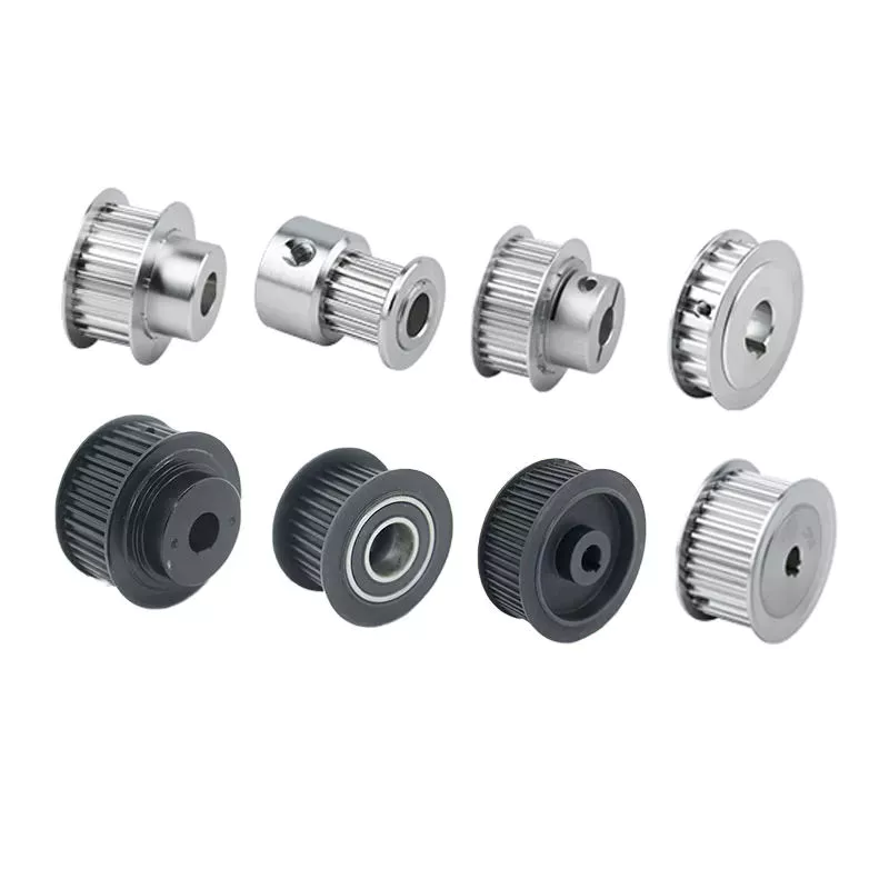
What is a pulley?Pulleys are shafts or wheels on a shaft that support the movement and change of direction of a taut cable. The pulley also transfers power from the shaft to the cable. A simple pulley is used to raise the school flag. Read on to learn about the basic types of pulleys. We also covered the use of pulleys in everyday life. Read on to learn more about this important mechanical part. composite pulleyA composite pulley is a mechanical system where 2 or more pulleys and ropes are connected together. It reduces the force required to lift the load because the force is divided by the distance of each pulley. Distance is equal to the mass of the object. Composite pulleys are a common mechanical system on sailboats. Composite pulleys can be used to lift heavy equipment such as sails. Fixed pulleyFixed pulleys are fixed gears of fixed length that are mounted on solid objects. There are many different types of pulley systems. Some cooperate with each other, but not "fixed". moving pulleyA movable pulley is a device whose part is fixed to another object, usually a rod or beam. The movable part moves with the load, making the load feel lighter. This is a useful tool for those who need to carry heavy items such as large bags. The advantages of moving pulleys are many. Here are some of them. Read on to learn more about them. School flag raised with simple pulleysHow is the school flag raised? It is pulled up by a rope attached to a pulley at the top of the pole. When the rope is pulled, the pulley turns, raising the flag. A pulley is a simple mechanism that helps people move heavier objects with ease. The rope must be securely attached to the pulley to keep the flag stable. cast iron pulleyIf you are looking for pulleys for your machine, you may come across cast iron pulleys. They are usually cheap and available in a variety of sizes. The rim is held in place by a mesh attached to a central boss. The arms and spokes can be straight or curved, but most are oval. There are many uses for this type of pulley.
| ||||||||||||||||||||||||||||||||||||||||||||||||||||||||||||||||||||||||||||||||||||||||||||||||||||||||||||||||||||||||||||||||||||||||||||||||||||||||||||||||||||||