Product Description
Product Description
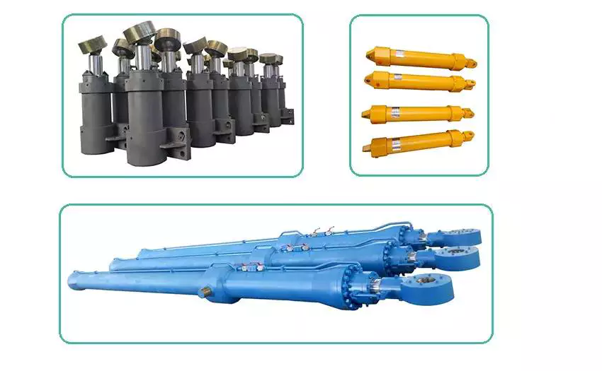
Offshore & marine hydraulic cylinder:
Due to use at sea of the Offshore & marine hydraulic cylinder, The environment temperature change and strong corrosive of seawater.
Thus for hydraulic cylinder requirement in addition to the running reliability and service life time. Also must has the very high corrosion resistance.
So we carried out on the hydraulic cylinder piston rod strict control of nickel plating,chrome plating or plating ceramics. The hydraulic cylinder outer surface of the strict coating, silica Gel, Etc, such surface treatment. To ensure the hydraulic cylinder without rust after long time running.
Our products have applications in:
- Port equipment;
- Offshore structures;
- Dredges;
- Hatch covers;
- Cranes and deck machinery;
- Steering gear;
- Etc.
Product Parameters
| Material | Carbon steel, Alloy steel, Stainless steel |
| Honed tube | 20-2500mm, Heat treatment, honing, rolling |
| Piston rod | 10-2000mm ,tempering, plated nickel, Chromium or ceramic |
| Working Pressure | 5-300Mpa |
| Seals | Parker,Merkel,Hallite |
| Technology | Bosch CHINAMFG and Parker |
| Coating | Sandblasting, primer, middle paint, finish paint |
| Temperature range | -40ºC to +300ºC |
| Work medium | Hydraulic Oil |
| Piston speed | maximum 2m/s |
| Mounting style | Earrings, flange, foot mounting, screw thread. |
Product Application
Company Show
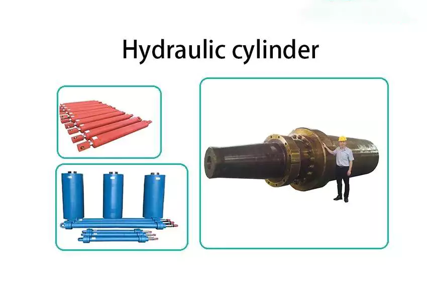
HETLOCK is a professional manufacturer of hydraulic cylinders in China, Founded in 1998, located in the international city of ZheJiang . Our plant is nearly 20000 square meter& We have 135 Employees including 11 experienced engineers and technical staff,More than 1800 type of hydraulic cylinder designed in every year. We can produce various kinds of hydraulic cylinders according to customer requirements.
The inside diameter of hydraulic cylinders can achieve the maximum 2500mm;
The hydraulic cylinders operating pressure can achieve the maximum 300MPa.
FAQ
Q1:Are you a manufacturer or trading company?
A: We are a manufacturer.
Q2: How many years of production experience do you have?
A: We have over 20 years of production experience.
Q3: Can it be customized?
A: Both standard and non-standard products can be customized.
Q4: How to ensure product quality?
A: We strictly follow the quality process for production and 100% inspection of each batch of products.
Q5: What services can you provide?
A: According to customer requirements, we can provide a one-stop solution from design, production, and delivery to meet their needs.
/* January 22, 2571 19:08:37 */!function(){function s(e,r){var a,o={};try{e&&e.split(",").forEach(function(e,t){e&&(a=e.match(/(.*?):(.*)$/))&&1
| Certification: | CE, ISO9001 |
|---|---|
| Pressure: | High Pressure |
| Work Temperature: | Normal Temperature |
| Acting Way: | Double Acting |
| Working Method: | Straight Trip |
| Adjusted Form: | Regulated Type |
| Customization: |
Available
|
|
|---|
How do hydraulic cylinders compare to other methods of force generation like electric motors?
Hydraulic cylinders and electric motors are two different methods of force generation with distinct characteristics and applications. While both hydraulic cylinders and electric motors can generate force, they differ in terms of their working principles, performance attributes, and suitability for specific applications. Here's a detailed comparison of hydraulic cylinders and electric motors:
1. Working Principle:
- Hydraulic Cylinders: Hydraulic cylinders generate force through the conversion of fluid pressure into linear motion. They consist of a cylinder barrel, piston, piston rod, and hydraulic fluid. When pressurized hydraulic fluid enters the cylinder, it pushes against the piston, causing the piston rod to extend or retract, thereby generating linear force.
- Electric Motors: Electric motors generate force through the conversion of electrical energy into rotational motion. They consist of a stator, rotor, and electromagnetic field. When an electrical current is applied to the motor's windings, it creates a magnetic field that interacts with the rotor, causing it to rotate and generate torque.
2. Force and Power:
- Hydraulic Cylinders: Hydraulic cylinders are known for their high force capabilities. They can generate substantial linear forces, making them suitable for heavy-duty applications that require lifting, pushing, or pulling large loads. Hydraulic systems can provide high force output even at low speeds, allowing for precise control over force application. However, hydraulic systems typically operate at lower speeds compared to electric motors.
- Electric Motors: Electric motors excel in providing high rotational speeds and are commonly used for applications that require rapid motion. While electric motors can generate significant torque, they tend to have lower force output compared to hydraulic cylinders. Electric motors are suitable for applications that involve continuous rotary motion, such as driving conveyor belts, rotating machinery, or powering vehicles.
3. Control and Precision:
- Hydraulic Cylinders: Hydraulic systems offer excellent control over force, speed, and positioning. By regulating the flow of hydraulic fluid, the force and speed of hydraulic cylinders can be precisely controlled. Hydraulic systems can provide gradual acceleration and deceleration, allowing for smooth and precise movements. This level of control makes hydraulic cylinders well-suited for applications that require precise positioning, such as in industrial automation or construction equipment.
- Electric Motors: Electric motors also offer precise control over speed and positioning. Through motor control techniques such as varying voltage, frequency, or pulse width modulation (PWM), the rotational speed and position of electric motors can be accurately controlled. Electric motors are commonly used in applications that require precise speed control, such as robotics, CNC machines, or servo systems.
4. Efficiency and Energy Consumption:
- Hydraulic Cylinders: Hydraulic systems can be highly efficient, especially when properly sized and designed. However, hydraulic systems typically have higher energy losses due to factors such as fluid leakage, friction, and heat generation. The overall efficiency of a hydraulic system depends on the design, component selection, and maintenance practices. Hydraulic systems require a hydraulic power unit to pressurize the hydraulic fluid, which consumes additional energy.
- Electric Motors: Electric motors can have high efficiency, especially when operated at their optimal operating conditions. Electric motors have lower energy losses compared to hydraulic systems, primarily due to the absence of fluid leakage and lower friction losses. The overall efficiency of an electric motor depends on factors such as motor design, load conditions, and control techniques. Electric motors require an electrical power source, and their energy consumption depends on the motor's power rating and the duration of operation.
5. Environmental Considerations:
- Hydraulic Cylinders: Hydraulic systems typically use hydraulic fluids that can pose environmental concerns if they leak or are not properly disposed of. The choice of hydraulic fluid can impact factors such as biodegradability, toxicity, and potential environmental hazards. Proper maintenance and leak prevention practices are essential to minimize the environmental impact of hydraulic systems.
- Electric Motors: Electric motors are generally considered more environmentally friendly since they do not require hydraulic fluids. However, the environmental impact of electric motors depends on the source of electricity used to power them. When powered by renewable energy sources, such as solar or wind, electric motors can offer a greener solution compared to hydraulic systems.
6. Application Suitability:
- Hydraulic Cylinders: Hydraulic cylinders are commonly used in applications that require high force output, precise control, and durability. They are widely employed in industries such as construction, manufacturing, mining, and aerospace. Hydraulic systems are well-suited for heavy-duty applications, such as lifting heavy objects, operating heavy machinery, or controlling large-scale movements.
- Electric Motors: Electric motors are widely used in various industries and applications that require rotational motion, speed control, and precise positioning. They are commonly found in appliances, transportation, robotics, HVAC systems, and automation. Electric motorsare suitable for applications that involve continuous rotary motion, such as driving conveyor belts, rotating machinery, or powering vehicles.In summary, hydraulic cylinders and electric motors have different working principles, force capabilities, control characteristics, efficiency levels, and application suitability. Hydraulic cylinders excel in providing high force output, precise control, and durability, making them ideal for heavy-duty applications. Electric motors, on the other hand, offer high rotational speeds, precise speed control, and are commonly used for applications that involve continuous rotary motion. The choice between hydraulic cylinders and electric motors depends on the specific requirements of the application, including the type of motion, force output, control precision, and environmental considerations.
Adaptation of Hydraulic Cylinders for Medical Equipment and Aerospace Applications
Hydraulic cylinders have the potential to be adapted for use in medical equipment and aerospace applications, offering unique advantages in these industries. Let's explore how hydraulic cylinders can be adapted for these specialized fields:
- Medical Equipment: Hydraulic cylinders can be adapted for various medical equipment applications, including hospital beds, patient lifts, surgical tables, and rehabilitation devices. Here's how hydraulic cylinders are beneficial in medical equipment:
- Positioning and Adjustability: Hydraulic cylinders provide precise and smooth movement, allowing for accurate positioning and adjustments of medical equipment. This is crucial for ensuring patient comfort, proper alignment, and ease of use.
- Load Handling: Hydraulic cylinders offer high force capabilities, enabling the safe handling of heavy loads in medical equipment. They can support the weight of patients, facilitate smooth transitions, and provide stability during procedures.
- Controlled Motion: Hydraulic cylinders provide controlled and stable motion, which is essential for delicate medical procedures. The ability to adjust speed, position, and force allows for precise and controlled movements, minimizing patient discomfort and ensuring accurate treatment.
- Durability and Reliability: Hydraulic cylinders are designed to withstand rigorous use and demanding environments, making them suitable for medical equipment applications. Their durability and reliability contribute to the long-term performance and safety of medical devices.
- Aerospace Applications: Hydraulic cylinders can also be adapted for aerospace applications, where lightweight yet robust systems are essential. Here's how hydraulic cylinders are advantageous in aerospace:
- Flight Control Systems: Hydraulic cylinders play a critical role in aircraft flight control systems, including ailerons, elevators, rudders, and landing gear. They provide precise and reliable actuation, allowing pilots to control the aircraft's movements with accuracy and responsiveness.
- Weight Optimization: Hydraulic cylinders can be designed using lightweight materials, such as aluminum alloys or composite materials, to reduce overall weight. This weight optimization is crucial in aerospace applications to enhance fuel efficiency, payload capacity, and aircraft performance.
- Shock and Vibration Resistance: Aerospace environments involve significant shock and vibration forces. Hydraulic cylinders can be engineered to withstand these dynamic loads while maintaining performance and reliability, ensuring consistent operation even under extreme conditions.
- Space Constraints: Hydraulic cylinders can be designed to fit within the space constraints of aircraft or spacecraft. Their compact size and flexible mounting options allow for efficient integration into the limited available space.
In summary, hydraulic cylinders can be adapted for use in medical equipment and aerospace applications, leveraging their precise positioning, load handling capabilities, controlled motion, durability, and reliability. In medical equipment, hydraulic cylinders enable comfortable patient positioning, smooth transitions, and controlled movements during procedures. In aerospace, hydraulic cylinders provide precise actuation, weight optimization, shock and vibration resistance, and space-efficient solutions. By adapting hydraulic cylinders to these specialized fields, manufacturers can meet the unique requirements and enhance the performance of medical equipment and aerospace systems.
How do hydraulic cylinders handle variations in load and pressure during operation?
Hydraulic cylinders are designed to handle variations in load and pressure during operation, making them versatile and efficient in various applications. Hydraulic systems use the principle of transmitting force through incompressible fluid to generate linear motion. Here's a detailed explanation of how hydraulic cylinders handle variations in load and pressure:
1. Load Handling:
- Hydraulic cylinders are capable of handling different loads by utilizing the principle of Pascal's law. According to Pascal's law, when pressure is applied to a fluid in a confined space, the pressure is transmitted equally in all directions. In a hydraulic cylinder, the force applied to the piston results in an equal force output at the rod end of the cylinder. The size of the piston and the pressure exerted determine the force generated by the cylinder. Therefore, hydraulic cylinders can handle a wide range of loads by adjusting the pressure applied to the fluid.
2. Pressure Compensation:
- Hydraulic systems incorporate pressure compensation mechanisms to handle variations in pressure during operation. Pressure compensating valves or regulators are often used to maintain a consistent pressure in the hydraulic system, regardless of load changes. These valves automatically adjust the flow rate or pressure to ensure stable and controlled operation of the hydraulic cylinder. By compensating for pressure variations, hydraulic cylinders can maintain a consistent force output and prevent damage or instability due to excessive pressure.
3. Control Valves:
- Control valves play a crucial role in managing variations in pressure and load during hydraulic cylinder operation. Directional control valves, such as spool valves or poppet valves, control the flow of hydraulic fluid into and out of the cylinder, enabling precise control of the cylinder's extension and retraction. By adjusting the position of the control valve, the speed and force exerted by the hydraulic cylinder can be regulated to match the load and pressure requirements of the application. Control valves allow for efficient handling of variations in load and pressure by providing fine-tuned control over the hydraulic system.
4. Accumulators:
- Hydraulic accumulators are often used to handle fluctuations in pressure and load. Accumulators store hydraulic fluid under pressure, which can be released or absorbed as needed to compensate for sudden changes in load or pressure. When the load on the hydraulic cylinder decreases, the accumulator releases stored fluid to maintain pressure and prevent pressure spikes. Conversely, when the load on the cylinder increases, the accumulator absorbs excess fluid to maintain system stability. By utilizing accumulators, hydraulic cylinders can effectively handle variations in load and pressure, ensuring smooth and controlled operation.
5. Feedback and Control Systems:
- Advanced hydraulic systems may incorporate feedback and control systems to monitor and adjust the operation of hydraulic cylinders in real-time. Position sensors or pressure sensors provide feedback on the cylinder's position, force, and pressure, allowing the control system to make continuous adjustments to optimize performance. These systems can automatically adapt to variations in load and pressure, ensuring precise control and efficient operation of the hydraulic cylinder.
6. Design Considerations:
- Proper design considerations, such as selecting the appropriate cylinder size, piston diameter, and rod diameter, are essential for handling variations in load and pressure. The design should account for the maximum anticipated load and pressure conditions to ensure the hydraulic cylinder operates within its specified range. Additionally, the selection of suitable seals, materials, and components that can withstand the anticipated load and pressure variations is crucial for maintaining the reliability and longevity of the hydraulic cylinder.
By utilizing the principles of hydraulic systems, incorporating pressure compensation mechanisms, employing control valves and accumulators, and implementing feedback and control systems, hydraulic cylinders can effectively handle variations in load and pressure during operation. These features and design considerations allow hydraulic cylinders to adapt and perform optimally in a wide range of applications and operating conditions.


editor by CX 2024-03-06
China best Telescopic Electric Hydraulic Double Acting Mini Pneumatic Rodless CZPT Top 2 Stage Power Chuck Sda Air Cylinder wholesaler
Product Description
FAQ
1. who are we?
We are based in ZheJiang , China, start from 2012,sell to Domestic Market(00.00%). There are total about 5-10 people in our office.
2. how can we guarantee quality?
Always a pre-production sample before mass production;
Always final Inspection before shipment;
3.what can you buy from us?
Hydraulic Pump,Hydraulic Valve,Proportional Valve
4. why should you buy from us not from other suppliers?
We are a hydraulic system, hydraulic cylinder, hydraulic pump, hydraulic valve research and development, production, sales as 1 of the enterprises.We have 20 years of experience in design and development.
5. what services can we provide?
Accepted Delivery Terms: FOB,CFR,CIF,EXW,FAS,CIP,FCA,CPT,DEQ,DDP,DDU,Express Delivery,DAF,DES;
Accepted Payment Currency:USD,EUR,JPY,CAD,AUD,HKD,GBP,CNY,CHF;
Accepted Payment Type: T/T,L/C,D/P D/A,MoneyGram,Credit Card,PayPal,Cash,Escrow;
Language Spoken:English,Spanish,Japanese,Portuguese,German,Arabic,French,Russian,Korean,Hindi,Italian
Drive shaft type
The driveshaft transfers torque from the engine to the wheels and is responsible for the smooth running of the vehicle. Its design had to compensate for differences in length and angle. It must also ensure perfect synchronization between its joints. The drive shaft should be made of high-grade materials to achieve the best balance of stiffness and elasticity. There are 3 main types of drive shafts. These include: end yokes, tube yokes and tapered shafts.
tube yoke
Tube yokes are shaft assemblies that use metallic materials as the main structural component. The yoke includes a uniform, substantially uniform wall thickness, a first end and an axially extending second end. The first diameter of the drive shaft is greater than the second diameter, and the yoke further includes a pair of opposing lugs extending from the second end. These lugs have holes at the ends for attaching the axle to the vehicle.
By retrofitting the driveshaft tube end into a tube fork with seat. This valve seat transmits torque to the driveshaft tube. The fillet weld 28 enhances the torque transfer capability of the tube yoke. The yoke is usually made of aluminum alloy or metal material. It is also used to connect the drive shaft to the yoke. Various designs are possible.
The QU40866 tube yoke is used with an external snap ring type universal joint. It has a cup diameter of 1-3/16" and an overall width of 4½". U-bolt kits are another option. It has threaded legs and locks to help secure the yoke to the drive shaft. Some performance cars and off-road vehicles use U-bolts. Yokes must be machined to accept U-bolts, and U-bolt kits are often the preferred accessory.
The end yoke is the mechanical part that connects the drive shaft to the stub shaft. These yokes are usually designed for specific drivetrain components and can be customized to your needs. Pat's drivetrain offers OEM replacement and custom flanged yokes.
If your tractor uses PTO components, the cross and bearing kit is the perfect tool to make the connection. Additionally, cross and bearing kits help you match the correct yoke to the shaft. When choosing a yoke, be sure to measure the outside diameter of the U-joint cap and the inside diameter of the yoke ears. After taking the measurements, consult the cross and bearing identification drawings to make sure they match.
While tube yokes are usually easy to replace, the best results come from a qualified machine shop. Dedicated driveshaft specialists can assemble and balance finished driveshafts. If you are unsure of a particular aspect, please refer to the TM3000 Driveshaft and Cardan Joint Service Manual for more information. You can also consult an excerpt from the TSB3510 manual for information on angle, vibration and runout.
The sliding fork is another important part of the drive shaft. It can bend over rough terrain, allowing the U-joint to keep spinning in tougher conditions. If the slip yoke fails, you will not be able to drive and will clang. You need to replace it as soon as possible to avoid any dangerous driving conditions. So if you notice any dings, be sure to check the yoke.
If you detect any vibrations, the drivetrain may need adjustment. It's a simple process. First, rotate the driveshaft until you find the correct alignment between the tube yoke and the sliding yoke of the rear differential. If there is no noticeable vibration, you can wait for a while to resolve the problem. Keep in mind that it may be convenient to postpone repairs temporarily, but it may cause bigger problems later.
end yoke
If your driveshaft requires a new end yoke, CZPT has several drivetrain options. Our automotive end yoke inventory includes keyed and non-keyed options. If you need tapered or straight holes, we can also make them for you.
A U-bolt is an industrial fastener that has U-shaped threads on its legs. They are often used to join 2 heads back to back. These are convenient options to help keep drivetrain components in place when driving over rough terrain, and are generally compatible with a variety of models. U-bolts require a specially machined yoke to accept them, so be sure to order the correct size.
The sliding fork helps transfer power from the transfer case to the driveshaft. They slide in and out of the transfer case, allowing the u-joint to rotate. Sliding yokes or "slips" can be purchased separately. Whether you need a new 1 or just a few components to upgrade your driveshaft, 4 CZPT Parts will have the parts you need to repair your vehicle.
The end yoke is a necessary part of the drive shaft. It connects the drive train and the mating flange. They are also used in auxiliary power equipment. CZPT's drivetrains are stocked with a variety of flanged yokes for OEM applications and custom builds. You can also find flanged yokes for constant velocity joints in our extensive inventory. If you don't want to modify your existing drivetrain, we can even make a custom yoke for you.


China best China Brand Dozer Prices Mini Hydraulic Cylinder Dh13 with Good quality
Product Description
Full hydraulic bulldozer
Hydraulic bulldozer DH13 130HP small dozer for sale
BULLDOZER
DH13-C2
ENGINE POWER
With 116kW/2000rpm, this engine conforms to EU Stage IIIA emission regulation.
OVERALL WEIGHT
13400kg/14000kg
ENGINE MODEL
QSB 6.7
BULLDOZER DH13
Power System
1. The installed electronic control engine meets the EU Stage IIIA emission regulation and features strong power, high energy-saving and environmental-friendliness, high parts universality, and low maintenance costs.
2. The Shantui's innovative hydrostatic drive optimization technology is applied to achieve higher efficiency and energy-saving, with the working efficiency at >68% and the CZPT fuel consumption reduced by 10%~15% compared with others machines of same horsepower range.
Control system
1. The double-module (Function and safety) controller architecture verifies with each other to achieve higher safety and reliability.
2. The malfunction self-diagnosis function is provided to accurately indicate the malfunction cause and orientation and shorten the downtime.
3. The service software with distinct access hierarchy features high simpleness and practicability and easy learning and understanding.
PARAMETER for SHXIHU (WEST LAKE) DIS.I DOZER
Full hydraulic bulldozer DH13-C2 SHXIHU (WEST LAKE) DIS.I mini dozer for sale
| Parameter name | DH13-C2 XL (Extended version) | DH13-C2 LGP(Super-wetland version) |
| Performance parameters | ||
| Operating weight (Kg) | 13400kg/29542lb (With traction frame) | 14000kg/30864lb (With traction frame) |
| Ground pressure (kPa) | 45.3 | 34.9/37.9 |
| Engine | ||
| Engine model | QSB6.7 | QSB6.7 |
| Rated power/rated speed (kW/rpm) | 116/2000 | 116/2000 |
| Overall dimensions | ||
| Overall dimensions of machine (mm) | 4924*3060*2988 | 4924*3380*2988 |
| Driving performance | ||
| Forward speed (km/h) | 0~10km/h(6.2mph) | 0~10km/h(6.2mph) |
| Reversing speed (km/h) | 0~10km/h(6.2mph) | 0~10km/h(6.2mph) |
| Chassis System | ||
| Center distance of track (mm) | 1780 | 2000 |
| Width of track shoes (mm) | 560 | 760/700 (Swamp type track shoe) |
| Ground length(mm) | 2640 | 2640 |
| Tank capacity | ||
| Fuel tank (L) | 275 | 275 |
| Working device | ||
| Blade type | Angle Blade | Angle Blade |
| Digging depth (mm) | 460 | 460 |
| Ripper type | Three-tooth ripper | Three-tooth ripper |
| Ripping depth (mm) | 500 | 500 |
Package and shipping of the SHXIHU (WEST LAKE) DIS.I BULLDOZER
SHXIHU (WEST LAKE) DIS.I DOZER CATALOG
CONTACT US:
| Nancy --------------------- Sale Manager ZheJiang CZPT Imp & Exp Co. Ltd. Add: HangZhou City, ZheJiang Provice, China Mobile: |
Guide to Drive Shafts and U-Joints
If you're concerned about the performance of your car's driveshaft, you're not alone. Many car owners are unaware of the warning signs of a failed driveshaft, but knowing what to look for can help you avoid costly repairs. Here is a brief guide on drive shafts, U-joints and maintenance intervals. Listed below are key points to consider before replacing a vehicle driveshaft.
Symptoms of Driveshaft Failure
Identifying a faulty driveshaft is easy if you've ever heard a strange noise from under your car. These sounds are caused by worn U-joints and bearings supporting the drive shaft. When they fail, the drive shafts stop rotating properly, creating a clanking or squeaking sound. When this happens, you may hear noise from the side of the steering wheel or floor.
In addition to noise, a faulty driveshaft can cause your car to swerve in tight corners. It can also lead to suspended bindings that limit overall control. Therefore, you should have these symptoms checked by a mechanic as soon as you notice them. If you notice any of the symptoms above, your next step should be to tow your vehicle to a mechanic. To avoid extra trouble, make sure you've taken precautions by checking your car's oil level.
In addition to these symptoms, you should also look for any noise from the drive shaft. The first thing to look for is the squeak. This was caused by severe damage to the U-joint attached to the drive shaft. In addition to noise, you should also look for rust on the bearing cap seals. In extreme cases, your car can even shudder when accelerating.
Vibration while driving can be an early warning sign of a driveshaft failure. Vibration can be due to worn bushings, stuck sliding yokes, or even springs or bent yokes. Excessive torque can be caused by a worn center bearing or a damaged U-joint. The vehicle may make unusual noises in the chassis system.
If you notice these signs, it's time to take your car to a mechanic. You should check regularly, especially heavy vehicles. If you're not sure what's causing the noise, check your car's transmission, engine, and rear differential. If you suspect that a driveshaft needs to be replaced, a certified mechanic can replace the driveshaft in your car.
Drive shaft type
Driveshafts are used in many different types of vehicles. These include four-wheel drive, front-engine rear-wheel drive, motorcycles and boats. Each type of drive shaft has its own purpose. Below is an overview of the 3 most common types of drive shafts:
The driveshaft is a circular, elongated shaft that transmits torque from the engine to the wheels. Drive shafts often contain many joints to compensate for changes in length or angle. Some drive shafts also include connecting shafts and internal constant velocity joints. Some also include torsional dampers, spline joints, and even prismatic joints. The most important thing about the driveshaft is that it plays a vital role in transmitting torque from the engine to the wheels.
The drive shaft needs to be both light and strong to move torque. While steel is the most commonly used material for automotive driveshafts, other materials such as aluminum, composites, and carbon fiber are also commonly used. It all depends on the purpose and size of the vehicle. Precision Manufacturing is a good source for OEM products and OEM driveshafts. So when you're looking for a new driveshaft, keep these factors in mind when buying.
Cardan joints are another common drive shaft. A universal joint, also known as a U-joint, is a flexible coupling that allows 1 shaft to drive the other at an angle. This type of drive shaft allows power to be transmitted while the angle of the other shaft is constantly changing. While a gimbal is a good option, it's not a perfect solution for all applications.
CZPT, Inc. has state-of-the-art machinery to service all types of drive shafts, from small cars to race cars. They serve a variety of needs, including racing, industry and agriculture. Whether you need a new drive shaft or a simple adjustment, the staff at CZPT can meet all your needs. You'll be back on the road soon!
U-joint
If your car yoke or u-joint shows signs of wear, it's time to replace them. The easiest way to replace them is to follow the steps below. Use a large flathead screwdriver to test. If you feel any movement, the U-joint is faulty. Also, inspect the bearing caps for damage or rust. If you can't find the u-joint wrench, try checking with a flashlight.
When inspecting U-joints, make sure they are properly lubricated and lubricated. If the joint is dry or poorly lubricated, it can quickly fail and cause your car to squeak while driving. Another sign that a joint is about to fail is a sudden, excessive whine. Check your u-joints every year or so to make sure they are in proper working order.
Whether your u-joint is sealed or lubricated will depend on the make and model of your vehicle. When your vehicle is off-road, you need to install lubricable U-joints for durability and longevity. A new driveshaft or derailleur will cost more than a U-joint. Also, if you don't have a good understanding of how to replace them, you may need to do some transmission work on your vehicle.
When replacing the U-joint on the drive shaft, be sure to choose an OEM replacement whenever possible. While you can easily repair or replace the original head, if the u-joint is not lubricated, you may need to replace it. A damaged gimbal joint can cause problems with your car's transmission or other critical components. Replacing your car's U-joint early can ensure its long-term performance.
Another option is to use 2 CV joints on the drive shaft. Using multiple CV joints on the drive shaft helps you in situations where alignment is difficult or operating angles do not match. This type of driveshaft joint is more expensive and complex than a U-joint. The disadvantages of using multiple CV joints are additional length, weight, and reduced operating angle. There are many reasons to use a U-joint on a drive shaft.
maintenance interval
Checking U-joints and slip joints is a critical part of routine maintenance. Most vehicles are equipped with lube fittings on the driveshaft slip joint, which should be checked and lubricated at every oil change. CZPT technicians are well-versed in axles and can easily identify a bad U-joint based on the sound of acceleration or shifting. If not repaired properly, the drive shaft can fall off, requiring expensive repairs.
Oil filters and oil changes are other parts of a vehicle's mechanical system. To prevent rust, the oil in these parts must be replaced. The same goes for transmission. Your vehicle's driveshaft should be inspected at least every 60,000 miles. The vehicle's transmission and clutch should also be checked for wear. Other components that should be checked include PCV valves, oil lines and connections, spark plugs, tire bearings, steering gearboxes and brakes.
If your vehicle has a manual transmission, it is best to have it serviced by CZPT's East Lexington experts. These services should be performed every 2 to 4 years or every 24,000 miles. For best results, refer to the owner's manual for recommended maintenance intervals. CZPT technicians are experienced in axles and differentials. Regular maintenance of your drivetrain will keep it in good working order.
China high quality CZPT Sy16c 1.75ton Hydraulic Arm Cylinder for CZPT Mini Excavator with Hot selling
Product Description
Benefits & Features
-
Higherefficiency
-
Lower fuel consumption
-
Operation comfort
-
Withwide applicationsin various narrow environments such as forest, farm & indoors.
Specifications
|
Technical Paraments |
|
|
Dimensions |
|
|
Overall length |
3575 mm |
|
Overall width |
980/1350 mm |
|
Overall height |
2420 mm |
|
Operation Range |
|
|
Max. CZPT height |
3665 mm |
|
Max. Dumping height |
2635 mm |
|
Max. vertical CZPT depth |
2215 mm |
|
Engine |
|
|
Model |
3TNV74F/3TNV70 |
|
Rated Power |
11.2/2400 kW/rpm |
|
Specification |
|
|
Overall Weight |
1750kg |
|
Bucket Capacity |
0.04 m3 |
|
Bucket CZPT force |
15.2 kN |
|
Service Capacities |
|
|
Fuel tank |
23L |
| If you need more details and need our support,Please contact me | |
Construction Case
Production Line of SY16C
Certification of SY16C Mini Excavator
FAQ
1: What kind terms of payment can be accepted?
A: For terms of payment, L/C, T/T, D/A, D/P, Western Union (can be) could accepted
2: What certificates are available in Machinery?
A: For the certificate, we have CE, ISO, Gost, EPA(USA)CCC,
3: What about the delivery time?
A: 7-20 days after receiving the deposit.
4: What about the warranty time?
A: 12 months after shipment or 2000 working hours, whichever occuts first.
5. What about the Minimum Order Quantity?
A: The MOQ is 1 pcs
Ball Screws - Dimensions, Applications, and Benefits
Ball screws are popular, lightweight, precision mechanical components. They are commonly used in machinery, gears, and knurled objects. These screw-like parts can be easily maintained and lubricated using oil. This article discusses their dimensions, applications, and benefits. The following sections provide additional information to help you select the right ball screw for your needs. We'll discuss some of the important characteristics of ball screws and what makes them so useful.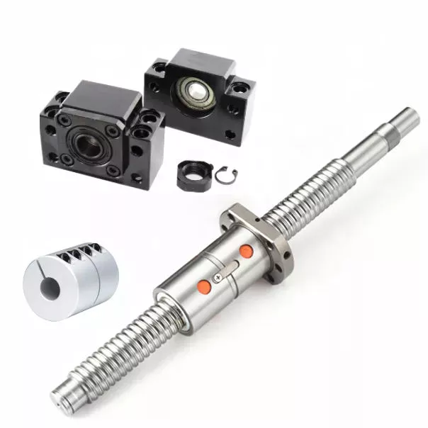
Preloading
A key problem with nut-to-ball screw backlash is the ability of the nut to move freely on the threads of the ball screw. To solve this problem, a patented solution was developed. The patent, 4,557,156, describes an innovative method for preloading ball screws and nuts. By applying a preloading nut, the threads of the ball screw are prevented from moving back and forth with the nut.
A mechanical design that involves axial play involves a lot of mass, inertia, and complexity. These characteristics lead to wear and rust problems. Preloading ball screws using a dynamic system reduces mechanical complexity by allowing preload to be adjusted while the mechanism is running. This also reduces the number of mechanical parts and simplifies manufacturing. Thus, the preloading method of the present invention is advantageous.
The servo motors used in the system monitor the output torque and adjust the power to 1 motor in a dynamic way, thus creating a torque differential between the balls. This torque differential in turn creates a preload force between the ball nuts. The servo motors' output torque is controlled in this manner, and the machine's backlash clearance can be precisely controlled. Hence, the machine can perform multiple tasks with increased precision.
Several prior art methods for preloading ball screws are described in detail in FIG. 3. The helical thread grooves of the ball screw 26 and the nut 24 define a pathway for roller balls to travel along. The stylized broken line indicates the general position of the axis of the ball roller screw 26. The corresponding ball screws are used in a number of applications. This technique may be used to manufacture custom-sized screws.
Lubrication
Ball screws are mechanical elements that roll balls through a groove. Improper lubrication can reduce the life of these screw elements. Improper lubrication can lead to shaft damage, malfunction, and decreased performance. This article discusses the importance of proper lubrication and how to do it. You can learn how to properly lubricate ball screws in the following paragraphs. Here are some tips to ensure long-term performance and safety of ball screws.
The first thing you should do is determine the type of lubricant you'll be using. Oils are preferred because they tend to remain inside the ball nut, and grease can build up in it. Oils also tend to have better anti-corrosion properties than grease. However, grease is more likely to be clogged with debris than oils. So, before you choose the lubricant that's right for your screw, make sure you wash it off.
The oil used in ball screw lubrication must be applied at a controlled rate. It can prevent metal-on-metal contact and clean out contaminants as it passes through the ball nut. However, oil as a lubricant is expensive and can contaminate the process if it mixes with the cutting fluid. Grease, on the other hand, is inexpensive, requires fewer applications, and does not contaminate process fluids.
If you use a synthetic oil for lubrication, make sure to choose a viscosity that is appropriate for the operating temperature. Oil viscosity can increase the temperature of the ball screw assembly, and excessive oil can reduce its life. A correct amount of oil will reduce the temperature of the ball screw assembly, while too little will increase friction and wear. Use the following guidelines to determine the right amount of oil for your screw.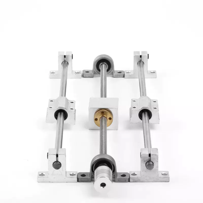
Dimensions
Dimensions of ball screws are a very important aspect to consider when determining the best type for your application. Technical acceptance conditions for ball screws specify the allowed deviations during acceptance tests. The tolerance class can also change, depending on the needs of a specific application. The following table lists the most important tolerance values for the full range of screw lengths. This table is a helpful guide when looking for a specific screw. The table below lists the dimensions of common ball screws.
The axial load applied to a ball screw is 0.5 x Fpr / 2Fpr. The minimum screw diameter is known as the root diameter. The axial load causes the screw shaft to deform in a certain way (DL1 and DL2). The elastic deflection induced by the load on a ball screw is called its rigidity. This rigidity is important for calculating sizing parameters for a ball screw.
The preload value of the ball screw affects the dynamic load capacity. A preload of 10 percent is considered adequate, while a value greater than this may compromise the screw's durability. In general, a high preload value will result in a lower dynamic load capacity and greater wear. However, the preload value must be calculated with the relevant screw parameters. This is because a high preload value reduces the screw's durability.
To ensure that your screw meets the specified parameters, the dynamic load capacity must be calculated. This is the amount of force a ball screw will withstand under a specified load. This calculation also includes strength checks. If you are using a ball screw for applications that need extra strength, it may require a safety factor. For example, if the screw is used for double-axial mounting, then the outer ball nut must be inserted into the nut, causing a secondary load.
Applications
The present invention provides a simple, yet highly effective way to mount a ball screw. Its absence of insert slots or through holes makes it simpler to assemble and provides a more uniform nut. The lack of mechanical features also reduces heat treatment issues, and the nut's hardness can be uniformly hardened. As a result, the screw's overall performance is improved. Here are some examples of applications for ball screws.
Preloading is the process of applying force to a ball screw. This increases the rigidity of the screw assembly and eliminates backlash, which is lost motion caused by clearance between the nut and ball. Backlash disrupts repeatability and accuracy. Spacer preloading involves inserting force between 2 ball nuts and transmitting it through the grooves. This method is ideal when preloading is needed in large quantities. In addition to increasing rigidity, preloading can improve accuracy.
Ball screws require careful care in their working surfaces to prevent contamination. Rubber or leather bellows can be used to protect their surfaces, while positive air pressure can be applied to the screw. Preloading eliminates backlash, a common problem among screw assemblies. In addition to the numerous applications for ball screws, they are also critical to computer-controlled motion-control systems and wire bonding. And there are many more examples. So what are the benefits of using these devices?
The spring preloading system uses a spring in between 2 ball nuts, applying tensional forces to the ball nuts. This spring creates grooves in the nut's middle, which facilitates recirculation of the balls. The spring preloading mechanism is more compact than the double nut mechanism, but the lengthening of the lead reduces the ball screw's load capacity. Its compact design makes it ideal for small clearance assemblies.
Maintenance
In addition to performing maintenance tasks yourself, the manufacturer of ball screws should offer reverse engineering services that will enable them to identify specific problems. The process of reverse engineering allows ball screw manufacturers to develop new ball screws and parts. In the event that a ball screw is beyond repair, a manufacturer can often save a significant amount of money by repairing it instead of replacing it. In addition to repairing a ball screw, the manufacturer should also offer free evaluation services for the component. Reconditioning and replacement involve the use of new parts, while reloading and replacement replace the screw.
Performing routine maintenance checks on ball screw assemblies is essential for maintaining optimal performance and extending their service life. Overtime, excessive wear can lead to a variety of problems, including backlash, vibration, and ball bearing noise. In addition, the increased friction increases the required torque for turning a screw, causing system failure and significant downtime. To ensure that a ball screw is fully functional, it must be checked for wear and maintain the proper lubrication system.
Discoloration or pitting on a ball screw indicates that it is in need of repair. The same is true if there are chatter marks in the ball groove. Oftentimes, a ball screw needs a new lubrication seal or wipers. Additionally, it may be missing or over-wearing, which could result in permanent failure. Finally, excessive power draw could be a sign of improper lubrication or improper installation.
Proper maintenance is essential for any machine tool. When performed properly, machine tools can last decades with continuous use. Proper care and maintenance is essential to ensure long life and optimal performance. In addition to improving machine tool uptime, proper maintenance affects the accuracy and repeatability of the end product. Therefore, premium machine tool manufacturers focus on the performance and durability of ball screws. They develop innovative designs and lubricants to optimize the lifespan of their products.
China wholesaler Mini Excavator Use Hydraulic Cylinder with Hot selling
Product Description
Condition: New
Applicable Industries: Machinery Repair Shops, Construction works
After Warranty Service: Video technical support, Online support
Video outgoing-inspection: Provided
Machinery Test Report: Provided
Marketing Type: New Product 2571
Place of Origin: ZheJiang , China
Warranty: 1 year
After-sales Service Provided: Video technical support, Online support
Certification: ISO9001
Color: yellow,blk
Material: 40cr+25mn
Surface Hardness: HRC52-58
Hardness Depth: 8-12mm
Name: Hydraulic cylinder
Supply Ability
Supply Ability: 60000 Pieces per year
Packaging & Delivery
Packaging Details: Standard export fumigated wooden pallet
Port: HangZhou port
|
Material |
40cr+25mn |
| Finish | Smooth |
| Colors | yellow,blk |
| Technique | Forging / casting |
| Surface Hardness | HRC52-58,deepth:8mm-12mm |
| Warranty time | 1 year |
| Certification | ISO9001 |
| Delivery Time | Within 30 days after contract established |
| BRAND | CATALOGUE | ||||||||
| BULLDOZER | D20 | D30 | D31 | D37 | D40 | D41 | D45 | D50 | D60 |
| D65 | D68 | D75 | D80 | D85 | D150 | D155 | D275 | D355 | |
| D3C | D3D | D4C | D4D | D4H | D5 | D6C | D6D | D6H | |
| D7G | D8K | D8N | D9N | D10N | D11N | ||||
| KOMATSU | PC30 | PC40 | PC45 | PC60 | PC75 | PC100 | PC120 | PC150 | PC200 |
| PC220 | PC300 | PC350 | PC400 | ||||||
| CATERPILLAR | E70B | E110 | E120B | E215 | E235 | E307 | E311 | E312 | E322 |
| E180 | E240 | E200B | E320 | E300 | E300B | E330 | E325 | ||
| HITACHI | EX30 | EX40 | EX60 | EX100 | EX120 | EX200 | EX220 | EX270 | EX300 |
| EX400 | EX600 | UH043 | UH052 | UH53 | UH07 | UH081 | UH082 | UH083 | |
| FIAT-HITACHI | FH120 | FH130 | FH150 | FH200 | FH220 | FH270 | FH300 | ||
| VOLVO | EC55 | EC130 | EC150 | EC200 | EC210 | EC240 | EC290 | EC360 | |
| DAEWOO | DH55 | DH130 | DH180 | DH200 | DH280 | DH300 | DH320 | ||
| HYUNDAI | R60 | R130 | R200 | R210 | R220 | R290 | R320 | R914 | |
| KATO | HD250 | HD400 | HD450 | HD700 | HD770 | HD820 | HD1250 | ||
| KOBELCO | SK40 | SK60 | SK100 | SK120 | SK200 | SK220 | SK04-2 | SK07 | |
| SK07N2 | SK09 | SK12 | SK14 | SK300 | SK310 | SK400 | |||
| JCB | JS70 | JS75 | JS110 | JS130 | JS160 | JS180 | JS200 | JS220 | |
| JS240 | JS260 | JS300 | JS330 | ||||||
| SUMITOMO | SH70 | SH100 | SH120 | SH160 | SH200 | SH260 | SH265 | SH280 | SH300 |
| SH340 | LS2650 | LS2800 | LS3400 | LS4300 | |||||
| MX8 | SE200 | SE210 | SE280 | MX292 | SE350 | ||||
| MITSUBISHI | MS110 | MS120 | MS140 | MS180 | |||||
All manufacturer's names,symbols&descriptions are used for reference purpose only,and it is not implied that and any part listed is the product of these manufacturers.
1. You are a trader or a manufacture?
We are an industry and trade integration business, our factory located on HangZhou Nanan Distric, and our sales department is in City centre of HangZhou. The distance is 80Kms, 1.5 hours.
2. How can I be sure the part will fit my excavator?
Give us correct model number/machine serial number/ any numbers on the parts itself. Or measure the parts give us dimension or drawing.
3. How about the payment terms?
We usually accept T/T or Trade Assurance. other terms also could be negotiated.
4. What is your minimum order?
It depends on what you are buying. Normally, our minimum order is one 20' full container and LCL container (less than a container load) can be acceptable.
5. What is your delivery time?
FOB HangZhou or any Chinese port : 20 days . If there are any parts in stock , our delivery time is only 0-7 days.
6. What about Quality Control?
We have a perfect QC system for the perfect products. A team who will detect the product quality and specification piece carefully, monitoring every production process until packing is complete, to ensure product safety into container.
What Is a Pulley?
The pulley is a wheel mounted on a shaft or axle. Its purpose is to support the movement of a cable that is taut. This cable transfers power to a shaft. However, there are certain safety precautions that you should follow when using a pulley. Read on to learn more! Listed below are common uses and their main parts. Listed below are some of the benefits of using a pulley.
Common uses of a pulley
A pulley is a common mechanical device used to increase the force needed to lift a heavy object. Most commonly, these devices are used in construction equipment. These machines use high-10sion ropes to transfer heavy objects from 1 floor to another. Other common uses of a pulley include buckets and flagpoles. These devices are extremely useful in a wide range of applications. To learn more about the common uses of pulleys, keep reading.
A pulley is a wheel with grooves for holding rope. Its purpose is to change the direction and point at which a pulling force acts. It is usually used in sets to reduce the amount of force needed to lift a load, but the work involved is similar. Pulleys are also used in rock climbing devices. For many applications, a pulley is a vital part of construction.
The most common use of a pulley involves hoisting and lowering a flag. Other examples include clotheslines, bird feeders, and escalators. Pulleys are also commonly used on oil derricks. Many other common applications include hoisting and lowering garage doors. Pulley systems are also used in engines and cranes. For more information, check out our interactive pulley diagram!
Pulleys can also be used to lower total work required for a task. In many cases, a pulley will consist of 2 parts: the pulley hub and the shaft pulley. The hub clamps the shaft pulley, while the pulley itself is connected to the motor or other device. If you're looking for a pulley, it's important to learn how it works.
The most common uses for a pulley involve lifting heavy objects, and the mechanism used to lift them is known as a pulley. A pulley is an industrial device that uses 2 wheels to reduce the force needed to lift a weight. The pulley reduces this force by half by allowing the user to pull on the rope 4 times as far. The pulley also allows for a smaller lifting distance.
Main parts of a pulley
A pulley consists of the main element of a system. This is typically a cable, rope, belt, or chain. There are 2 basic types of pulleys - a Driver Pulley and a Follower Pulley. Pulleys are available in small and large sizes. The periphery part of the pulley is called the Face, and the protruding middle part is called the Crown. A pulley's face can be round, rectangular, or even "V" shaped.
The first pulley was created by the Greek mathematician Archimedes in the third century BCE. These simple machines are made of a rope, an axle, and a wheel. The pulley's end is attached to a person, object, or motor. These machines can be used in various tasks to lift heavy objects. The pulley is a great mechanical advantage for any lifter.
The ideal mechanical advantage of a pulley is defined by the number of rope segments that pull an object. The higher the number of loops on the rope, the higher the mechanical advantage. The greater the mechanical advantage, the less force is required to move the object. Likewise, the greater the distance the rope traverses, the higher the mechanical advantage of a pulley. There are several different types of pulley, depending on their combination of rope, wheel, and rope.
The basic components of a pulley are the face and hub, and the rope is threaded into the center of the pulley. The pulley is usually made of a rope and can be used to lift heavy weights. It can also be used to apply great force in any direction. Step pulleys have multiple faces, which are fixed in sequence. They can also increase the speed of the driven pulley.
A pulley is a simple machine consisting of a wheel, rope, or chain. These parts are crucial for making moving and lifting easier. Because they change the direction and magnitude of force, they can be a useful tool. Some pulleys even change direction. You can learn more about the pulley by downloading this resource today. The resources are designed to support the new 9-1 GCSEs in Design & Technology and Engineering.
Mechanical advantage
Pulleys have been used to move heavy objects for centuries. When 2 rope sections are used, the weight of a 100kg mass can be moved with only 500 newtons of force. Adding an extra pulley increases the mechanical advantage. If the pulley has 2 wheels, the distance between the rope sections and the wheel grooves is only half the distance, but the mechanical advantage still applies. Adding another pulley increases the mechanical advantage, but can be risky.
Mechanical advantage is the ratio of force used versus force applied. The calculations are made under the assumption that the ropes and weights do not elongate or lose energy due to friction. If the weights are very light, the mechanical advantage is greater than that in the real world. To calculate the mechanical advantage, the weight of the load to be lifted must be the same as the weight of the person using the pulley.
A single moveable pulley has a mechanical advantage of two. The weight passes around the pulley, and 1 end of the rope is attached to a fixed point. The pulling force is then applied to the other end of the rope. The distance the weight travels doubles, or halved, depending on the direction of the pulley. Adding a second pulley reduces the distance and the effort required to lift it.
There are several ways to calculate the mechanical advantage of a pulley system. Some methods are specific to certain types of systems, while others work for all systems. The T-Method is a good choice in many applications, as it calculates the units of tension for each rope segment. Once you have determined the input force, you need to determine the maximum force that will be applied to each component. A compound pulley, for example, will require 4 units of tension for each rope segment.
In simple terms, the effort is the amount of force needed to lift the load. This force is measured in newtons (N). A mechanical advantage is often presented without units. If the student does not have this unit, you may need to convert the units to newtons, since 1 kilogram is equal to 10 newtons. If you can't figure out the units of effort, you can use the KWL chart provided by the teacher.
Safety precautions
There are a few safety precautions you should take when using a pulley. First, always check the SWL (safe working load) before attaching anything to the pulley. This indicates the maximum weight and angle the pulley can safely handle. Second, make sure that your work area is free from people and debris. Third, wear a hard hat to protect your head from blows and falling objects.
Another important consideration is anchoring. Although the pulley reduces the weight of an object, it is not enough to eliminate the weight. This is especially true if you are hoisting a heavy object, such as a motorcycle or lawnmower. It is important to ensure that the anchoring point can support the entire weight of the load. It is also important to follow proper anchoring procedures when using a pulley to lift a motorcycle or lawnmower.
In addition to the safety latch, you should use a tag line to control the suspended load. Remember that a chain pulley block is necessary for vertical lifting. You should also wear personal protective equipment (PPE) while using a pulley to avoid injuries. If your workplace does not have an PPE policy, you should consider implementing a similar policy. These safety guidelines are a good start.
If you are using a pulley to lift heavy objects, make sure to wear gloves. Those who are not familiar with rope-pulling will have an easier time demonstrating how it works. If you are using a rope-pulley system in a classroom, be sure to follow lab safety guidelines. Wear cloth gloves, clear the area, and do not jerk the rope. In addition, never allow yourself to be pulled into the rope by an unfamiliar person.
Another important safety precaution when using a pulley is to ensure that the anchor point for your system is adequate to support the weight of the object being lifted. Check with the manufacturer of the pulley to find out what its weight limit is, as some types of pulleys are designed to lift much heavier weights than others. It is important to follow all manufacturer's instructions when using a pulley.
China Custom SMC Type Ma Pneumatic Finger Cylinder Hydraulic Pneumatic Mini Cylinder with Hot selling
Product Description
If you are interested in our products, please contact us before placing an order, thank you!
Types of agricultural parts
Agricultural parts can be divided into different categories. These components include tractors, moldboard plows, whips and sickles. Some of the different types of agricultural ingredients are listed below. Each of these parts is important for different types of farming. It is important to know the purpose of each and what it does. If you are a farmer or plan to become a farmer, these parts are critical to your operation. 
Tractor
The first tractor appeared in the 1920s. Ford and International Harvester were among the first companies to produce farm tractors, but the industry has grown rapidly. By the 1920s, hundreds of companies were producing farm tractors. The agricultural depression of the 1930s forced many of these companies out of business. By the 1930s, only 7 companies were major players in the tractor business. Ford produced the largest number of wheeled tractors in the United States between 1930 and 1955.
Some tractors are equipped with various accessories to enhance their performance. These specialized agricultural components are used for a variety of tasks. These include tillage, harvesting, planting and material handling. Tractors vary in horsepower, lift capacity, control and capabilities. Some models also have device mounting options. The downside of this is that if you need to use the tractor for other purposes, you will have to use additional attachments that can damage the tractor.
Modern tractors have a clutch pedal on the gear lever. This allows you to shift quickly without pedaling. Other tractors have a throttle speed button that improves hydraulic flow to the implement. However, the most important component of a tractor is the engine. Tractors must be driven safely because even minor accidents can cause serious damage to farm equipment. While there are many tractors that can operate without these parts, you can find the right tractor for your job.
Shared plows
One of the many uses of shared plows as part of agriculture is to increase the amount of soil in a field. This plow effectively removes compacted soil and lifts weed roots. According to the University of Nebraska-Lincoln Institute for Agriculture and Natural Resources, plowshares are best used in the fall, when weeds are less active and the soil is more fertile.
The basic plowshare can be adjusted by raising or lowering the plowshare to suit runners in the furrow. However, this design is not suitable for breaking up the heavier soils of northern Europe. In the 6th century, however, the advent of the wheel made it possible to use larger moldboards, which increased food production and population growth. Today, farmers in North America have access to a wide variety of moldboard plows.
Agricultural moldboard plows come in 2 basic styles, horse-drawn or tractor-style. Horse-drawn models have 1 bottom, while tractor-pulled moldboard plows have 1 to 14 hydraulically raised bottoms. Other variants include intermediate breakers and twin moldboard plows. Agricultural moldboard plows are often used in the Midwest and elsewhere.
Grass
Grass is used for mowing. The blade is double edged and bolted to the wooden handle. Steel blades are tempered and braced for strength and durability. The blade can be sharpened if necessary. The straw whip is 30 inches long, which can be a good or a bad thing depending on the user's height. Blades can be sharpened with sandpaper or a file.
The traditional straw whip 32 includes a rear panel and horizontal shelves. It also features a hollow handle with an adapter at the proximal end and a carrying handle at the distal end. The first cable goes to the power supply and goes through the case and handle. After pulling the cable taut, the straw will be firmly attached to the small holder 8.
The suction tube 32 is connected to an electrical connection 47 that powers the device. A battery pack is provided for use away from the tractor. It is a plastic or metal box and consists of 2 parts: a rechargeable battery 67 and a female electrical plug 68. The switch locks in the open position to prevent accidental use. The switch is also equipped with a safety lock button. These 2 components work together to operate the straw.
Scythe
Although it is generally believed that the scythe was first developed in Roman times, its actual development may be earlier. Pliny mentioned 2 different types of sickles, Gallic and Roman. The Gallic sickle was the longer of the 2 and was made of mild steel, while the Roman sickle was made of harder, higher carbon steel.
In the past, people cut wheat by hand with a sickle. They replaced scythes and bagging hooks, which required users to bend over to harvest crops. Although they have largely been replaced by tractor machinery, scythes are still used today in parts of Asia and Europe. The sickle can also reach awkward corners, making it more useful in certain types of cuts.
The sickle belt stretches from Europe to the Middle East and the Midwest of the United States and Canada. It also spans most of Russia, the Middle East and North Africa. In the 19th century, Austrian sickle makers dominated the sickle industry. They produced millions of sickles, some dating back to the 1500s. Some of them were exported to India and the former Soviet Union.
Brushcutter
Brushcutters are powerful agricultural tools used primarily for felling and trimming vegetation. These parts are often multifunctional, and some models are even capable of maintaining road edges and ditches. Some models can even trim branches from certain types of trees. Before you buy your own brush cutter, be sure to read the manual carefully and follow the safety rules. For your own safety and the safety of others, please wear a hard hat, eye and hearing protection, padded gloves, long pants, and boots, and keep young children away from work areas.
Brushcutters are usually attached to the tractor via a 3-point linkage system, with the exception of high reach models that are attached to the tractor via fixed stirrups. Additionally, brush cutters often have a balancing mass located opposite the tractor. These agricultural components are complicated to install, but once installed, they remain coupled to the tractor. A brush cutter is a critical piece of equipment on any tractor.
Most brushcutters use hydraulic engines. The power is transmitted mechanically through a PTO (power take-over) mechanism or a cardan shaft, which turns a hydraulic pump. This pump draws hydraulic oil from a special tank and then sends it through a series of distributors to move the arm and the working organ. As a result, the power of the brush cutter is transferred from the tractor to the working organ by a hydraulic engine.
Transplanters
Transplanters for agricultural parts are equipment used to plant seedlings into soil. These machines are used in greenhouses and open fields to increase productivity, yield, and the success of harvesting transplanted crops. Transplanters are typically made of steel and are designed to fit seedlings of all shapes and sizes. Buying a used transplanter is a good idea as long as the working parts are in good condition. When considering a used model, you should inspect it for cracks or corrosion and broken parts.
A mechanical transplanter works faster than hand transplanting, but it becomes slower as your quads and back start hurting. Water-wheel transplanters have become popular in recent years. By automatically delivering water into the holes where the transplants are set, water is delivered to the root system without the need for manual intervention. Moreover, water-wheel transplanters save time on watering. John Good, a farmer who uses a water-wheel transplanter, says that speed is no different between a mechanical transplanter and a water-wheel one.
Cultivatorsw
The basic purpose of cultivators is to turn soil and plant matter into a workable form for the crops. Cultivators are used by both large and small farmers. Cultivators for small farming operations are usually self-propelled, but may be drawn behind a tractor. Two-wheel cultivators are typically fixed and powered by couplings, while four-wheel cultivators are attached via a three-point hitch and operated by power take-off. Some cultivators are still drawn behind a draft animal, and the methods are still used in many developing countries.
Cultivators are used in farming to break up soil around a crop. There are 3 different kinds of cultivators: row crop cultivators, disc cultivators, and power cultivators. Row crop cultivators are used to break up soil before planting, while harrows are used to prepare the soil for planting. In both cases, cultivators are used to disturb the soil consistently throughout the working width. In general, cultivating soil improves aeration and disrupts photosynthesis. Moreover, it can decrease water ponding time after heavy rainfall.
Cultivators are important parts of agricultural machinery. They aerate soil, prepare the seedbed, and kill weeds. By disrupting the soil, cultivators are used to evenly distribute chemical applications. Among them, glyphosate is the most common and widely used weed killer. It is safe for farmers to use, and it effectively eliminates most weeds in a single application.
China OEM Cheap Arm Excavator Hydraulic Cylinder Cheap Mini Excavator Hydraulic Cylinder Price with Best Sales
Product Description
Our competitive products:
Shantui bulldozer parts
| Model | Part Name |
| SSD16 SD22,SD23 ,SD32,SD42 | Engine Related Parts (Radiator, Fan, Power take-off) |
| Torque Converter (Turbine Pump, Stator, Gear, Relief Valve bearings) | |
| Transmission Parts (Carrier, Friction, Plate, Shaft) | |
| Steering System Parts (Steering clutch, Spiral bevel, Steering valve) | |
| Final Drive Parts (Pinion, Sprocket ,Hub, Drum, Bearing) | |
| Undercarriage parts | |
| Lift cylinder, tilt cylinder ,ripper cylinder |
Komastu bulldozer / mining truck/ excavator parts
Caterpillar bulldozer / excavator parts
|
Machinery Brand |
Machinery Type |
Product Models |
|
CATERPILLAR |
Bulldozer |
D3B,D3C,D3G,D4B,D4C,D4G,D4H,D5C,D5K, D5M,D5N,D5G,D5H,D6D,D6E,D6G,D6M,D6H, D7D,D7G,D7H,D7R,D8N,D8L.D8R,D8T, D9N,D9T,D9R,D10N,D10T,D10R etc. |
|
Excavator |
305D,305E,306D,306E,307C,307E,308C, 308E,312D,313D,315D,315C,320C,320D, 323D,324D,325C,325D,329D,330D, 336D,345D,349D, 365D,385D etc. |
|
|
KOMATSU |
Bulldozer |
D20,D30,D31,D40,D41,D45,D50,D53, D55,D57,D60,D61,D65,D75,D85, D155,D275,D355,D375,D475 etc. |
|
Excavator |
PC20,PC30,PC35,PC40,PC45,PC50,PC60, PC70,PC75,PC90,PC100, PC120, PC130, PC200, PC220, PC270,PC280,PC300, PC360,PC400,PC600, PC650,PC850 etc. |
ZheJiang JOINT-WINNING CONSTRUCTION MACHINERY CO., LTD. specializes in all kinds of construction machinery parts, located in HangZhou City, 1 of China's construction machinery industry bases. With more than 15 years of experience in the industry, we are CZPT to select the most cost-effective products for our customers and ensure that every part sold is suitable for your equipment!
FAQ
Q1:What's your terms of packing?
A1:Generally, we pack our goods in carton box,heavy parts will pack by wooden box or pallet.
Q2: What services can we provide?
A2: Accepted Delivery Terms: FOB,EXW,DPT; Accepted Payment Currency:USD,EUR,CNY; Accepted Payment Type: T/T,PayPal,Western Union,Cash; Language Spoken:English,Chinese,Spanish
Before shipping ,we will take the parts image to you to check first ,if no question ,then send it .We will send you the tracking number by email ,and track for you every 2days . Save packing and short delivery time. Good Service , 24H online Reply and Competitive Price with Better Quality.
Q3:Why should you buy from us not from other suppliers?
A3: ZheJiang Joint-winning Construction Machinery Co., Ltd. as specialized supplier and exporter for this parts in China for many years with competitive price .Brand such as Kobelco, Hyundai, Volvo, Doosan, Komatsu, Caterpillar, Kato, Sumitomo, Shantui and so on. We can check parts with part number and machine mode.
Q4:How do you make our business long-trem and good relationship?
A4:1.We keep good quality and competitive price to ensure our customers benefits;
2.We respect every customer as our friend and we sincerely do business and make friend with them ,no matter where they come from.
Q5:What's your delivery time ,and how long does it take to my destination ?
A5:Normally it will take about 20-30 days to reach your destination ,also depending on which country you're in .
Advantages of Ball Bearings
What is a ball bearing? A ball bearing is a type of rolling-element bearing that utilizes balls to maintain separation between 2 bearing races. Its contact angle between the balls and the races helps it reduce friction between the loads. There are several advantages to ball bearings, including their ability to withstand water. Read on to learn more. Here are a few of the benefits. You can use them in your daily life, from your car to your boat.
Ball bearings reduce friction between loads
Ball bearings reduce friction between loads by constraining the relative motion between moving parts. These bearings consist of a ring of small metal balls that reduce friction between moving objects. The name "ball bearing" is derived from the verb "to bear." The lubricant within the bearing reduces friction between moving particles. In a machine, ball bearings reduce friction between moving parts and improve linear motion around a fixed axis.
These bearings are commonly used to reduce friction between loads in rotating machines. They have 2 tracks, 1 fixed to the rotating part and 1 stationary. The rolling balls of a ball bearing have lower friction than flat surfaces. Because of this, they are useful for bar stool bearings. They reduce friction between surfaces and maintain the separation between bearing races. Hence, minimal surface contact is possible. Ball bearings have the potential to increase the life of machines and reduce energy consumption.
Ball bearings can be as small as a wrist watch or as large as an industrial motor. They function the same way, reducing friction between loads. Among their many uses, ball bearings are essential for everyday operations. Clocks, air conditioners, fans, and automobile axles all use ball bearings. In fact, anything that uses a motor requires ball bearings. It's no wonder they're gaining popularity in industries and everyday life.
They support radial and axial loads
Radial ball bearings are used primarily for radial loads, but they also have a capacity for axial load. This load capacity is usually given as a percentage of the radial load rating. Axial load capacity is generally greater for a bearing with a larger difference between the inner and outer ring diameters. The axial load capacity is also affected by the bearing's raceway depth, with shallow raceways being more suitable for heavier axial loads.
The 2 main types of axial and radial loads are defined by their orientation. Axial loads apply forces in 1 direction while radial loads act on the opposite direction. In both cases, the bearing must support the forces that are imposed. Axial loads apply forces to a bearing in a single direction, while radial loads apply forces in both directions. Regardless of the type of load, axial and radial loads should be considered when selecting a bearing for a given application.
Angular and radial ball bearings differ in their materials. Radial ball bearings are made largely of through-hardened materials. They typically have a Rockwell hardness rating of 58 Rc. The raceways and balls of these bearings are made of 440C stainless steel. They may also contain shields and seals. SAE 52100 steel is the most common material for the raceway, while molybdenum steels are excellent for high temperatures.
They have a contact angle between the balls and the races
When comparing axial load bearings with their radial counterparts, the angular contact angle is more important. Axial load bearings, have a contact angle between the balls and the races of 35 degrees. They are suitable for axial loads and a limited radial load. The contact angle of these bearings is a result of the shape of the inner and outer rings. Each rolling element comes into contact with the inner and outer rings only at 1 point, forming a 30 degree angle with the radial plane. The radial force of the axial load on these bearings is therefore increased by increasing the contact angle between the balls and the races.
This contact angle determines the amount of friction between the balls and the races, and allows angular contact bearings to withstand heavy radial and thrust loads. In addition, the larger the contact angle, the greater the axial load support. Angular contact bearings come in standard imperial (inch) and metric (mm) sizes. The angular contact angle is determined by the free radial play value and the curvature of the inner track.
They are water-resistant
In addition to their water-resistant qualities, corrosion-resistant ball bearings can also protect against the damaging effects of corrosive environments. Generally, standard metals, such as steel, are susceptible to rust, which can significantly reduce their performance and extend the life of parts. However, plastics, stainless steel, and ceramics can provide corrosion-resistant ball bearings. And because these materials are much more durable, they offer other advantages, such as being easy to maintain.
Among the advantages of plastic ball bearings is their high resistance to extreme temperatures, high speeds, and corrosion. Depending on their construction, plastic bearings are often able to resist corrosion and anti-static properties. They're lightweight and inexpensive compared to steel ball bearings. CZPT Sales Corporation was established in 1987 with a modest turnover of 4 lacs. As of the last financial year, it has grown to 500 lacs in sales.
Other advantages of water-resistant ball bearings include corrosion resistance, which is a key consideration in many applications. While stainless steel is highly corrosion-resistant, it decreases the bearing's load-carrying capacity. Also, corrosion-resistant deep groove ball bearings are usually made with a specified internal clearance, which absorbs loss in clearance during mounting and shaft expansion. This factor affects their performance, and if these are compromised, a replacement may be necessary.
They are tough
A few things make ball bearings tough: they're made of real materials, which means that they have inherent imperfections. Grade-1 balls are made especially for high-stress applications, such as Formula One engines. Grade-3 balls, on the other hand, strike the perfect balance between performance and cost. Ceramic balls, for example, are made to spin at a high rate of 400 RPM, and they're finished with a mirror finish.
A steel carbon ball bearing is 1 of the toughest forms of ball bearings available. The material is incredibly strong, but the contact between the balls isn't the best. Low-carbon steel is best for linear shafting and is usually coated with a polymer to prevent damage. Steel ball bearings with moderate amounts of carbon are tough, durable, and water-resistant. They're ideal for gears, but their high-carbon steel counterparts are particularly tough and can resist corrosion.
A ceramic ball bearing is another option. This type has steel inner and outer rings but ceramic balls. Ceramic balls can withstand higher temperatures than steel and are also electrically insulating. Ceramic ball bearings also tend to be lighter and are more resistant to wear and tear. They're also ideal for applications in which grease is not an option, such as in space shuttles. Despite the fact that ceramic ball bearings are tough, they're still cheaper than steel ball bearings.
They are conductive
You may have heard the term "ball bearing" if you've studied introductory physics. What does that mean? Essentially, ball bearings are conductive because of their ability to conduct electricity. This ability is reflected in the charge distribution on the surface of the ball. Positive charges are drawn toward the positive plate, while negative charges are drawn away from the positively charged ball bearing. You may have even seen a ball bearing in action.
However, despite their conductive nature, ball bearings can still become damaged by electrical discharge. A higher voltage can cause the balls to pit, and the raceways to become uneven. These uneven surfaces will first show up as excessive noise, and eventually cause the bearing to malfunction. Fortunately, engineers have found a way to counter this problem: conductive grease. This grease enables current to flow through the ball bearing, preventing both heat and voltage buildup.
The difference between steel and ceramic ball bearings is their density. Steel bearings are more conductive than glass or hybrid ceramics. Steel ball bearings have an even grain structure and are conductive for resonance flow. When moving fast, the air surrounding the steel ball bearing carries resonance from the inner ring to the outer. This makes them ideal for high-speed resonance transfer. In addition to being conductive, glass microbeads are harder and lighter than steel.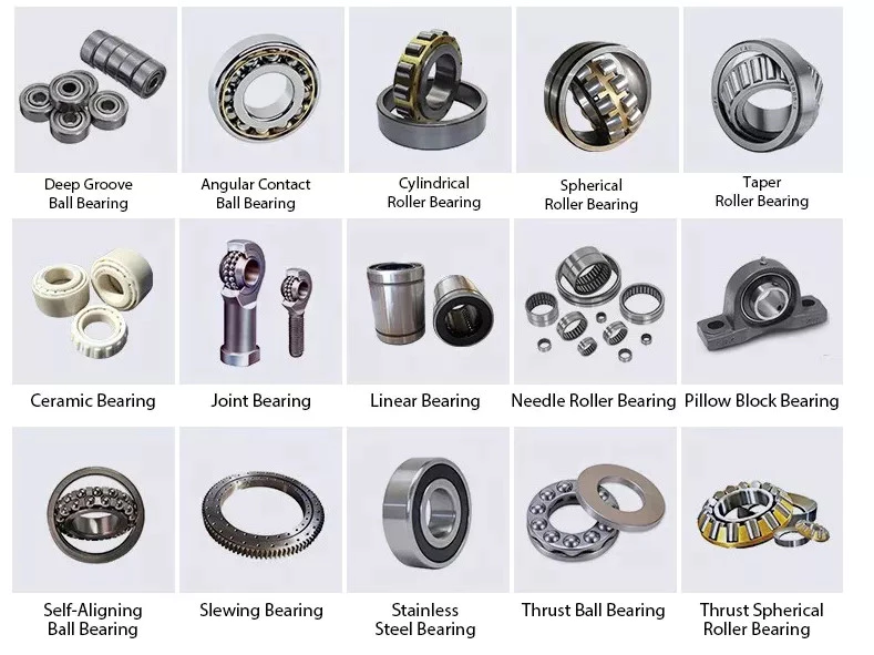
They are used in pulley systems
Pulley systems use ball bearings to move the sprocket, which is a wheel that rotates. These bearings are installed on the center mounting hole of the pulley wheel. They protect the entire system from heat, while allowing higher speed and smooth operation. They distribute the weight of the load evenly, minimizing friction and wobbling, and ensure a smooth rotation. Ball bearings are typically made from steel and are installed inside the pulley wheel.
The moment of inertia and bearing friction are measured to within 10 percent accuracy. These 2 variables affect the speed of the pulley system, which can lead to crashes if the weight holders are not balanced. Therefore, ball bearings are used to minimize the chance of such crashes. When you want to know more about ball bearings in pulley systems, here are the advantages they provide.
Another benefit of ball bearings in pulley systems is that they have lower friction than their solid counterparts. In order to reduce friction, however, ball bearings must be made of good materials. Some of the common ball materials are high-quality plastics and stainless steel. Good materials and clever block design are essential to minimizing friction. If you are planning to use ball bearings in your pulley system, check out the following tips and make sure you are choosing the right 1 for your application.
China OEM Good Quanlity Mini Hydraulic Mal Pneumatic Piston Cylinder near me factory
Product Description
Good Quanlity mini hydraulic MAL pneumatic piston cylinder:
Company Show
Calculate the ideal mechanical advantage of pulleys
The basic equations for pulleys can be found in this article. It will also cover the different types of pulleys, the ideal mechanical advantages of pulleys, and some common uses of pulley systems. Read on to learn more! After all, a pulley is a simple mechanical device that changes the direction of a force. Learn more about pulleys and their common uses in engineering.
pulley basic equation
Pulleys work the same way as gravity, so they should withstand similar forces. Newton's laws of motion can be used to calculate the forces in a pulley system. The second law of motion applies to forces and accelerations. Similar to this is Newton's third law, which states that the directions of forces are equal and opposite. The fourth law dictates the direction of force. The Fifth Law states that tension is in equilibrium with gravity.
A pulley is a simple mechanism that transmits force by changing direction. They are generally considered to have negligible mass and friction, but this is only an approximation. Pulleys have different uses, from sailboats to farms and large construction cranes. In fact, they are the most versatile mechanisms in any system. Some of their most common applications and equations are listed below.
For example, consider 2 masses m. Those of mass m will be connected by pulleys. The static friction coefficient of the left stop is ms1, and the static friction coefficient of the right stop is ms2. A no-slip equation will contain multiple inequalities. If the 2 blocks are considered to be connected by a pulley, the coefficient of kinetic friction is mk. In other words, the weight of each block carries the same mass, but in the opposite direction.
Types of pulleys
A pulley is a device used to pull and push objects. Pulley systems are ropes, cables, belts or chains. The "drive pulley" is attached to the shaft and moves the driven pulley. They are available in a variety of sizes, and the larger they are, the higher the speed of power transmission. Alternatively, use small pulleys for smaller applications.
Two-wheel pulleys have 2 mechanical advantages. The greater the mechanical advantage, the less force is required to move the object. More wheels lift more weight, but smaller pulleys require less force. In a two-wheel pulley system, the rope is wound around 2 axles and a fixed surface. As you pull on the rope, the shafts above slowly come together.
Compound pulleys have 2 or more rope segments that are pulled up on the load. The mechanical advantage of compound pulleys depends on the number of rope segments and how they are arranged. This type of pulley can increase the force by changing the direction of the rope segment. There are 2 main types of pulleys. Composite pulleys are most commonly used in construction. The ideal mechanical advantage of pulleys is 2 or more.
Construction pulleys are a basic type. They are usually attached to wheel rails and can be lifted to great heights. Combinations of axes are also common. Construction pulleys can be raised to great heights to access materials or equipment. When used in construction, these pulleys are usually made of heavy materials such as wood or metal. They are secured with ropes or chains.
The ideal mechanical advantage of pulleys
The pulley system is a highly complex system with high mechanical advantages. Use a single pulley system to reduce the force required to lift an object by cutting it in half. The mechanical advantage increases as you add more pulleys, such as 6 or seven. To calculate the mechanical advantage of a pulley system, you need to count the number of rope segments between the pulleys. If the free end of the rope is facing down, don't count it. If it's facing up, count. Once you have your number, add it up.
The required mechanical advantage of a pulley is the number of rope segments it has to pull the load. The more rope segments, the lower the force. Therefore, the more rope segments the pulley has, the lower the force. If the rope segments are four, then the ideal mechanical advantage is four. In this case, the composite pulley quadrupled the load force.
The ideal mechanical advantage of a pulley system is the sum of the mechanical force and the force required to lift the load at its output. Typically, a single pulley system uses 2 ropes, and the mechanical force required to lift the load is multiplied by the 2 ropes. For a multi-pulley system, the number of ropes will vary, but the total energy requirement will remain the same. The friction between the rope and pulley increases the force and energy required to lift the load, so the mechanical advantage diminishes over time.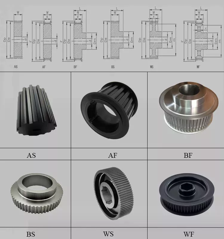
Common uses of pulley systems
A pulley system is a simple mechanical device typically used to lift heavy objects. It consists of a rotating wheel attached to a fixed shaft and a rope attached to it. When the wheel moves, the force applied by the operator is multiplied by the speed of the pulley, and the force is multiplied by the weight of the object being lifted. Common uses for pulley systems include pulling, lifting, and moving heavy objects.
The oil and petroleum industries use pulley systems in a variety of applications. Most commonly, pulleys are used in drilling operations and they are installed on top of the rig to guide the cable. The cable itself is attached to 2 pulleys suspended in the derrick, where they provide mechanical energy to the cable. Using a pulley system in this application provides the force needed to move the cable safely and smoothly.
The main advantage of the pulley system is that it minimizes the force required to lift an object. The force used to lift the object is multiplied by the desired mechanical advantage. The more rope segments, the lower the force required. On the other hand, a compound pulley system can have many segments. Therefore, a compound pulley system can increase the force a worker can exert on an object.
Safety Precautions to Take When Working on Pulley Systems
There are many safety precautions that should be observed when working on a pulley system. The first is to wear proper protective gear. This includes hard hats that protect you from falling objects. Also, gloves may be required. You should limit the amount of movement in the penalty area, and you should also keep the area free of unnecessary people and objects. Also, remember to wear a hard hat when working on the pulley system.
Another important safety precaution when working on a pulley system is to check the Safe Working Load (SWL) of the pulley before attaching anything. This will help you understand the maximum weight the pulley can hold. Also, consider the angle and height of the pulley system. Always use safety anchors and always remember to wear a hat when working on a pulley system.
Safe use of chain hoists requires training and experience. It is important to read the manufacturer's manual and follow all safety precautions. If you're not sure, you can actually inspect the hoist and look for signs of damage or tampering. Look for certifications for sprocket sets and other lifting accessories. Look for the Safe Working Load (SWL) marking on the chain hoist.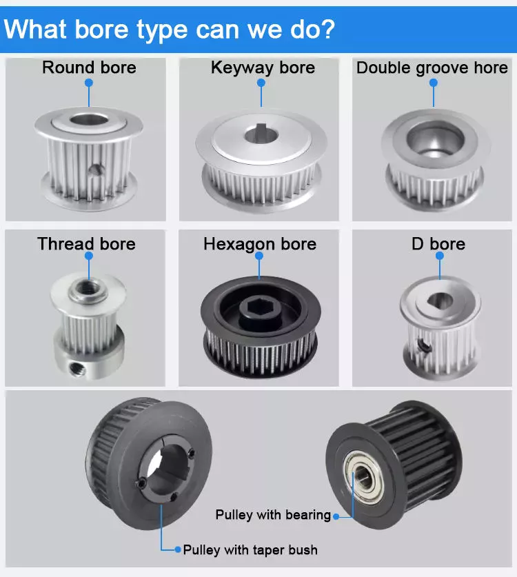
Example of a pulley system
Pulley systems are often used to lift items. It allows you to reduce the effort to lift and move the load by applying force in 1 direction. Pulley systems can be built and modeled to fit any type of project. This resource focuses on pulley systems and is designed to support the new GCSEs in Engineering, Design and Technology. There are also many examples of pulley systems suitable for various applications.
In the study, participants who read easy text took longer to manipulate the pulley system than those who read challenging text. In general, this suggests that participants with prior scientific experience used their cognitive abilities more effectively. Additionally, students who read simple texts spent less time planning the pulley system and more time on other tasks. However, the study did show that the time required to plan the pulley system was similar between the 2 groups.
In everyday life, pulley systems are used to lift various objects. Flagpoles are 1 of many pulley systems used to raise and lower flagpoles. They can also be used to raise and lower garage doors. Likewise, rock climbers use pulleys to help them ascend and descend. The pulley system can also be used to extend the ladder.
China supplier Manufacturers Price Long Stroke 100 50 Ton Press Ryco Manuli CZPT Style Mini Small Lifting Double Single Acting Piston Telescopic Hydraulic Cylinder for Sale with Great quality
Product Description
Products Description
|
Product Name |
HSG Series Hydraulic Cylinder |
|||
|
Work Press |
7/14/16/21/31.5MPa 37.5/63MPa Can be Customized |
|||
|
Material |
Aluminum,Cast Iron,45mnb Steel,Stainless Steel |
|||
|
Bore Size |
40mm--320mm,Customizable |
|||
|
Shaft Diameter |
20mm--220mm,Customizable |
|||
|
Stroke Length |
30mm--14100mm,Customizable |
|||
|
Rod Surface Hardness |
HRC48-54 |
|||
|
Paint Color |
Black,Yellow,Blue,Brown,Customizable |
|||
|
Mounting |
Earring,Flange,Clevis.Foot,Trunnion,Customizable |
|||
|
Warrenty |
1 Year |
|||
|
MOQ |
1 Piece |
|||
|
Delivery Time |
7-15 Days,Also depands on specific demands |
|||
|
Certification |
ISO9001,CE |
|||
Company Profile
QIANGLIN HYDRAULIC MACHINERY CO., LTD
| QiangLin is a professional hydraulic equipment manufacturer, mainly engaged in hydraulic system design, manufacture, installation, transformation, sales, and technical services. Our manufacturing facilities are certified to the ISO 9001 standard. We are an approved supplier to many equipment manufacturers in China. We are also partners with many customers from America, Canada, Australia, Germany, England, and other European Countries. Product quality, shorter delivery time, and customer satisfaction are our long-term commitments to our worldwide customers. Hope to be your partner. |
FAQ:
Q1: Are you a trading company or a manufacturer?
A: We have our own factory.
Q2: Are you CZPT to make Non-standard or customized products?
A: Yes, we can.
Q3: How long is your delivery time?
A: Normally, the delivery time is 7 days if we have stock, 15-30 working days if we don't. but it
also depends on the product
requirements and quantity.
Q4: Do you provide samples? are the samples free or not?
A: Yes, we can provide samples, but they are not free of charge.
Q5: What are your payment terms?
A: 30% deposit T/T or Irrevocable L/C at sight, If you have any questions, please feel free to
contact us.
Q6: What are your After-sales services?
A: Before shipment, Each individual product will be strictly inspected on our factory QC Process
System. In addition, We have a
Customer Service team to respond to customers' questions within 12 hours. Being helpful in
solving customers' problems is always our goal.
How to tell if your driveshaft needs replacing
What is the cause of the unbalanced drive shaft? Unstable U-joint? Your car may make clicking noises while driving. If you can hear it from both sides, it might be time to hand it over to the mechanic. If you're not sure, read on to learn more. Fortunately, there are many ways to tell if your driveshaft needs replacing.
unbalanced
An unbalanced driveshaft can be the source of strange noises and vibrations in your vehicle. To fix this problem, you should contact a professional. You can try a number of things to fix it, including welding and adjusting the weight. The following are the most common methods. In addition to the methods above, you can use standardized weights to balance the driveshaft. These standardized weights are attached to the shaft by welders.
An unbalanced drive shaft typically produces lateral vibrations per revolution. This type of vibration is usually caused by a damaged shaft, missing counterweights, or a foreign object stuck on the drive shaft. On the other hand, torsional vibrations occur twice per revolution, and they are caused by shaft phase shifts. Finally, critical speed vibration occurs when the RPM of the drive shaft exceeds its rated capacity. If you suspect a driveshaft problem, check the following:
Manually adjusting the imbalance of a drive shaft is not the easiest task. To avoid the difficulty of manual balancing, you can choose to use standardized weights. These weights are fixed on the outer circumference of the drive shaft. The operator can manually position the weight on the shaft with special tools, or use a robot. However, manual balancers have many disadvantages.
unstable
When the angular velocity of the output shaft is not constant, it is unstable. The angular velocity of the output shaft is 0.004 at ph = 29.5 and 1.9 at t = 1.9. The angular velocity of the intermediate shaft is not a problem. But when it's unstable, the torque applied to it is too much for the machine. It might be a good idea to check the tension on the shaft.
An unstable drive shaft can cause a lot of noise and mechanical vibration. It can lead to premature shaft fatigue failure. CZPT studies the effect of shaft vibration on the rotor bearing system. They investigated the effect of flex coupling misalignment on the vibration of the rotor bearing system. They assume that the vibrational response has 2 components: x and y. However, this approach has limited application in many situations.
Experimental results show that the presence of cracks in the output shaft may mask the unbalanced excitation characteristics. For example, the presence of superharmonic peaks on the spectrum is characteristic of cracks. The presence of cracks in the output shaft masks unbalanced excitation characteristics that cannot be detected in the transient response of the input shaft. Figure 8 shows that the frequency of the rotor increases at critical speed and decreases as the shaft passes the natural frequency.
Unreliable
If you're having trouble driving your car, chances are you've run into an unreliable driveshaft. This type of drivetrain can cause the wheels to stick or not turn at all, and also limit the overall control of the car. Whatever the reason, these issues should be resolved as soon as possible. Here are some symptoms to look for when diagnosing a driveshaft fault. Let's take a closer look.
The first symptom you may notice is an unreliable drive shaft. You may feel vibrations, or hear noises under the vehicle. Depending on the cause, it could be a broken joint or a broken shaft. The good news is that driveshaft repairs are generally relatively inexpensive and take less time than a complete drivetrain replacement. If you're not sure what to do, CZPT has a guide to replacing the U-connector.
One of the most common signs of an unreliable driveshaft is clanging and vibration. These sounds can be caused by worn bushings, loose U-joints, or damaged center bearings. This can cause severe vibration and noise. You can also feel these vibrations through the steering wheel or the floor. An unreliable driveshaft is a symptom of a bigger problem.
Unreliable U-joints
A car with an unreliable U-joint on the drive shaft can be dangerous. A bad u-joint can prevent the vehicle from driving properly and may even cause you trouble. Unreliable u-joints are cheap to replace and you should try getting parts from quality manufacturers. Unreliable U-joints can cause the car to vibrate in the chassis or gear lever. This is a sure sign that your car has been neglected in maintenance.
Replacing a U-joint is not a complicated task, but it requires special tools and a lot of elbow grease. If you don't have the right tools, or you're unfamiliar with mechanical terminology, it's best to seek the help of a mechanic. A professional mechanic will be able to accurately assess the problem and propose an appropriate solution. But if you don't feel confident enough, you can replace your own U-connector by following a few simple steps.
To ensure the vehicle's driveshaft is not damaged, check the U-joint for wear and lubrication. If the U-joint is worn, the metal parts are likely to rub against each other, causing wear. The sooner a problem is diagnosed, the faster it can be resolved. Also, the longer you wait, the more you lose on repairs.
damaged drive shaft
The driveshaft is the part of the vehicle that connects the wheels. If the driveshaft is damaged, the wheels may stop turning and the vehicle may slow down or stop moving completely. It bears the weight of the car itself as well as the load on the road. So even a slight bend or break in the drive shaft can have dire consequences. Even a piece of loose metal can become a lethal missile if dropped from a vehicle.
If you hear a screeching noise or growl from your vehicle when shifting gears, your driveshaft may be damaged. When this happens, damage to the u-joint and excessive slack in the drive shaft can result. These conditions can further damage the drivetrain, including the front half. You should replace the driveshaft as soon as you notice any symptoms. After replacing the driveshaft, you can start looking for signs of wear.
A knocking sound is a sign of damage to the drive shaft. If you hear this sound while driving, it may be due to worn couplings, damaged propshaft bearings, or damaged U-joints. In some cases, the knocking noise can even be caused by a damaged U-joint. When this happens, you may need to replace the entire driveshaft, requiring a new one.
Maintenance fees
The cost of repairing a driveshaft varies widely, depending on the type and cause of the problem. A new driveshaft costs between $300 and $1,300, including labor. Repairing a damaged driveshaft can cost anywhere from $200 to $300, depending on the time required and the type of parts required. Symptoms of a damaged driveshaft include unresponsiveness, vibration, chassis noise and a stationary car.
The first thing to consider when estimating the cost of repairing a driveshaft is the type of vehicle you have. Some vehicles have more than one, and the parts used to make them may not be compatible with other cars. Even if the same car has 2 driveshafts, the damaged ones will cost more. Fortunately, many auto repair shops offer free quotes to repair damaged driveshafts, but be aware that such work can be complicated and expensive.
China Standard China Supplier Tsish Custom Design Small Piston Micro Bore Mini Rod Short Stroke Double Acting Hydraulic Cylinder for Scissor Lift Table Farm Tractor Loader with Great quality
Product Description
small piston double acting hydraulic cylinder lift farm tractor loader
Product Description
Eaton, parker, hercules, prince, cross type double acting hydraulic cylinder are used for Trailer, Agricultural Machinery, Garbage Truck, Landing Platform etc.
Tsingshi hydraulic Customers, MAN, JAC, VOLVO, SHACMAN, DAF, JMC, HUNO, CIMC, SINOTRUK, TATRA,BENS,XIHU (WEST LAKE) DIS.FENG, FOTON,etc.
1.Piston rod electroplate hard chrome;
2.lighter and easier to maintenance double acting hydraulic cylinder;
3.High quality alloy seamless steel pipe have better mechanical properties;
4.The world famous brands of seals, such as Parker, Merkel, Hallite, Kaden, etc;
5.World-class processing technology ensures stable and reliable quality.
| NO | ITEM | double acting hydraulic cylinder DATA |
| 1 | Material | Carbon Steel, Alloy Steel, 27SiMn,45#,20#,etc |
| 2 | Honed tube | 40-300mm, Heat treatment, honing, rolling |
| 3 | Honed tube | 30-280mm, plated nickel or hard Chrome or ceramic |
| 4 | Seal kit | Parker, Merkel, Hallite, Kaden, etc |
| 5 | Coating | Sandblasting, primer paint, middle paint, finish paint, Color can paint according to customer demands. |
| 6 | Technology | double acting hydraulic cylinder |
| 7 | Mounting type | Pin-eye , flange, trunnion mount,ball mount, screw thread. FC, FE, FEE, FSE,TPIN |
| 8 | Working medium | Hydraulic Oil |
| 9 | Working pressure | 16-20Mpa double acting hydraulic cylinder |
| 10 | Temperature range | -50°C to +100°C |
Detailed Photos
Company Profile
Tsingshi hydraulic is a hydraulic telescopic cylinder for dump tipper truck company which takes up with hydraulic design, R&D, manufacturer, sell and service hydraulic products-double acting hydraulic cylinder.
-double acting hydraulic cylinder Certification ISO9001 TS16949, etc;
-mini double acting hydraulic cylinder Export to North America, South America, Australia, South Korea, Southeast Asia, South Africa, Europe, Middle East, etc;
-ODM&OEM small double acting hydraulic cylinder according to client's requirements;
-Professional manufacturer& supplier of Hydraulic Cylinders over 30 years;
-The micro double acting hydraulic cylinder can be used for Dump Truck, Tipper Truck, Trailer, Agricultural Machinery, Garbage Truck,Landing Platform etc; We can produce the follow brand hydraulic cylinder. HYVA, BINOTTO, EDBRO, PENTA, MAILHOT, CUSTOM HOIST, MUNCIE, METARIS, HYDRAULEX GLOBAL, HYCO, PARKER, COMMERCIAL HYDRAULICS, MEILLER. WTJX, XT, JX, HCIC, ZX, SZ, SJ.
CUSTOMERS PHOTOS
QUALITY GUARANTEE
HIGH QUALITITY GUARANTEE-double acting hydraulic cylinder
-7*24 service.
-Competitive price.
-Professional technical team.
-Perfect after-sales service system.
-ODM&OEM Hydraulic Cylinder according to customer needs.
-Strong Hydraulic Cylinder production capacity to ensure fast delivery.
-Guarantee Quality. Every process must be inspected, all products need be tested before leaving the factory.
<hydraulic cylinder double acting Leak Test
<mini hydraulic cylinder Buffer Test
<small hydraulic cylinder Reliability Test
<micro hydraulic cylinder Full Stroke Test
<mini double acting hydraulic cylinder Operation Test
<micro double acting hydraulic cylinder Pressure Tight Test
<small double acting hydraulic cylinder Load Efficiency Test
<double action hydraulic cylinder Start-up Pressure Test
<double acting hydraulic cylinder Testing the Effect of Limit
SALES AND SERVICE
PRODUCTS SERIES
ONE WORLD ONE LOVE
How to Choose the Right Worm Shaft
You might be curious to know how to choose the right Worm Shaft. In this article, you will learn about worm modules with the same pitch diameter, Double-thread worm gears, and Self-locking worm drive. Once you have chosen the proper Worm Shaft, you will find it easier to use the equipment in your home. There are many advantages to selecting the right Worm Shaft. Read on to learn more.
Concave shape
The concave shape of a worm's shaft is an important characteristic for the design of a worm gearing. Worm gearings can be found in a wide range of shapes, and the basic profile parameters are available in professional and firm literature. These parameters are used in geometry calculations, and a selection of the right worm gearing for a particular application can be based on these requirements.
The thread profile of a worm is defined by the tangent to the axis of its main cylinder. The teeth are shaped in a straight line with a slightly concave shape along the sides. It resembles a helical gear, and the profile of the worm itself is straight. This type of gearing is often used when the number of teeth is greater than a certain limit.
The geometry of a worm gear depends on the type and manufacturer. In the earliest days, worms were made similar to simple screw threads, and could be chased on a lathe. During this time, the worm was often made with straight-sided tools to produce threads in the acme plane. Later, grinding techniques improved the thread finish and reduced distortions resulting from hardening.
When a worm gearing has multiple teeth, the pitch angle is a key parameter. A greater pitch angle increases efficiency. If you want to increase the pitch angle without increasing the number of teeth, you can replace a worm pair with a different number of thread starts. The helix angle must increase while the center distance remains constant. A higher pitch angle, however, is almost never used for power transmissions.
The minimum number of gear teeth depends on the angle of pressure at zero gearing correction. The diameter of the worm is d1, and is based on a known module value, mx or mn. Generally, larger values of m are assigned to larger modules. And a smaller number of teeth is called a low pitch angle. In case of a low pitch angle, spiral gearing is used. The pitch angle of the worm gear is smaller than 10 degrees.
Multiple-thread worms
Multi-thread worms can be divided into sets of one, two, or 4 threads. The ratio is determined by the number of threads on each set and the number of teeth on the apparatus. The most common worm thread counts are 1,2,4, and 6. To find out how many threads you have, count the start and end of each thread and divide by two. Using this method, you will get the correct thread count every time.
The tangent plane of a worm's pitch profile changes as the worm moves lengthwise along the thread. The lead angle is greatest at the throat, and decreases on both sides. The curvature radius r" varies proportionally with the worm's radius, or pitch angle at the considered point. Hence, the worm leads angle, r, is increased with decreased inclination and decreases with increasing inclination.
Multi-thread worms are characterized by a constant leverage between the gear surface and the worm threads. The ratio of worm-tooth surfaces to the worm's length varies, which enables the wormgear to be adjusted in the same direction. To optimize the gear contact between the worm and gear, the tangent relationship between the 2 surfaces is optimal.
The efficiency of worm gear drives is largely dependent on the helix angle of the worm. Multiple thread worms can improve the efficiency of the worm gear drive by as much as 25 to 50% compared to single-thread worms. Worm gears are made of bronze, which reduces friction and heat on the worm's teeth. A specialized machine can cut the worm gears for maximum efficiency.
Double-thread worm gears
In many different applications, worm gears are used to drive a worm wheel. These gears are unique in that the worm cannot be reversed by the power applied to the worm wheel. Because of their self-locking properties, they can be used to prevent reversing motion, although this is not a dependable function. Applications for worm gears include hoisting equipment, elevators, chain blocks, fishing reels, and automotive power steering. Because of their compact size, these gears are often used in applications with limited space.
Worm sets typically exhibit more wear than other types of gears, and this means that they require more limited contact patterns in new parts. Worm wheel teeth are concave, making it difficult to measure tooth thickness with pins, balls, and gear tooth calipers. To measure tooth thickness, however, you can measure backlash, a measurement of the spacing between teeth in a gear. Backlash can vary from 1 worm gear to another, so it is important to check the backlash at several points. If the backlash is different in 2 places, this indicates that the teeth may have different spacing.
Single-thread worm gears provide high speed reduction but lower efficiency. A multi-thread worm gear can provide high efficiency and high speed, but this comes with a trade-off in terms of horsepower. However, there are many other applications for worm gears. In addition to heavy-duty applications, they are often used in light-duty gearboxes for a variety of functions. When used in conjunction with double-thread worms, they allow for a substantial speed reduction in 1 step.
Stainless-steel worm gears can be used in damp environments. The worm gear is not susceptible to rust and is ideal for wet and damp environments. The worm wheel's smooth surfaces make cleaning them easy. However, they do require lubricants. The most common lubricant for worm gears is mineral oil. This lubricant is designed to protect the worm drive.
Self-locking worm drive
A self-locking worm drive prevents the platform from moving backward when the motor stops. A dynamic self-locking worm drive is also possible but does not include a holding brake. This type of self-locking worm drive is not susceptible to vibrations, but may rattle if released. In addition, it may require an additional brake to keep the platform from moving. A positive brake may be necessary for safety.
A self-locking worm drive does not allow for the interchangeability of the driven and driving gears. This is unlike spur gear trains that allow both to interchange positions. In a self-locking worm drive, the driving gear is always engaged and the driven gear remains stationary. The drive mechanism locks automatically when the worm is operated in the wrong manner. Several sources of information on self-locking worm gears include the Machinery's Handbook.
A self-locking worm drive is not difficult to build and has a great mechanical advantage. In fact, the output of a self-locking worm drive cannot be backdriven by the input shaft. DIYers can build a self-locking worm drive by modifying threaded rods and off-the-shelf gears. However, it is easier to make a ratchet and pawl mechanism, and is significantly less expensive. However, it is important to understand that you can only drive 1 worm at a time.
Another advantage of a self-locking worm drive is the fact that it is not possible to interchange the input and output shafts. This is a major benefit of using such a mechanism, as you can achieve high gear reduction without increasing the size of the gear box. If you're thinking about buying a self-locking worm gear for a specific application, consider the following tips to make the right choice.
An enveloping worm gear set is best for applications requiring high accuracy and efficiency, and minimum backlash. Its teeth are shaped differently, and the worm's threads are modified to increase surface contact. They are more expensive to manufacture than their single-start counterparts, but this type is best for applications where accuracy is crucial. The worm drive is also a great option for heavy trucks because of their large size and high-torque capacity.