Product Description
Product Description
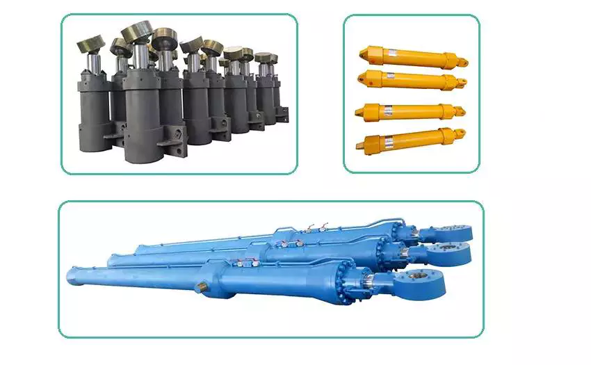
Offshore & marine hydraulic cylinder:
Due to use at sea of the Offshore & marine hydraulic cylinder, The environment temperature change and strong corrosive of seawater.
Thus for hydraulic cylinder requirement in addition to the running reliability and service life time. Also must has the very high corrosion resistance.
So we carried out on the hydraulic cylinder piston rod strict control of nickel plating,chrome plating or plating ceramics. The hydraulic cylinder outer surface of the strict coating, silica Gel, Etc, such surface treatment. To ensure the hydraulic cylinder without rust after long time running.
Our products have applications in:
- Port equipment;
- Offshore structures;
- Dredges;
- Hatch covers;
- Cranes and deck machinery;
- Steering gear;
- Etc.
Product Parameters
| Material | Carbon steel, Alloy steel, Stainless steel |
| Honed tube | 20-2500mm, Heat treatment, honing, rolling |
| Piston rod | 10-2000mm ,tempering, plated nickel, Chromium or ceramic |
| Working Pressure | 5-300Mpa |
| Seals | Parker,Merkel,Hallite |
| Technology | Bosch CHINAMFG and Parker |
| Coating | Sandblasting, primer, middle paint, finish paint |
| Temperature range | -40ºC to +300ºC |
| Work medium | Hydraulic Oil |
| Piston speed | maximum 2m/s |
| Mounting style | Earrings, flange, foot mounting, screw thread. |
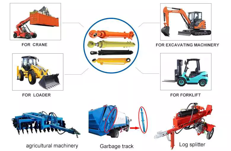
Product Application
Company Show
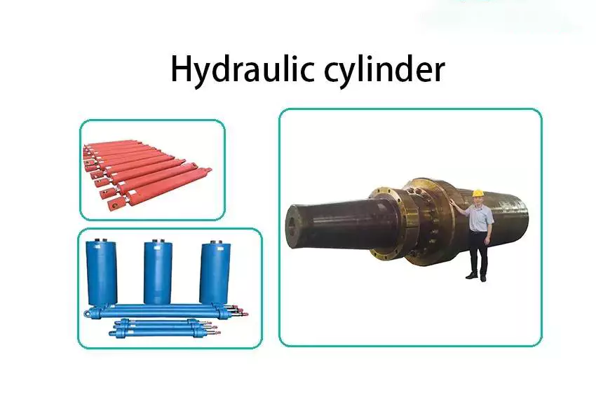
HETLOCK is a professional manufacturer of hydraulic cylinders in China, Founded in 1998, located in the international city of ZheJiang . Our plant is nearly 20000 square meter& We have 135 Employees including 11 experienced engineers and technical staff,More than 1800 type of hydraulic cylinder designed in every year. We can produce various kinds of hydraulic cylinders according to customer requirements.
The inside diameter of hydraulic cylinders can achieve the maximum 2500mm;
The hydraulic cylinders operating pressure can achieve the maximum 300MPa.
FAQ
Q1:Are you a manufacturer or trading company?
A: We are a manufacturer.
Q2: How many years of production experience do you have?
A: We have over 20 years of production experience.
Q3: Can it be customized?
A: Both standard and non-standard products can be customized.
Q4: How to ensure product quality?
A: We strictly follow the quality process for production and 100% inspection of each batch of products.
Q5: What services can you provide?
A: According to customer requirements, we can provide a one-stop solution from design, production, and delivery to meet their needs.
/* January 22, 2571 19:08:37 */!function(){function s(e,r){var a,o={};try{e&&e.split(",").forEach(function(e,t){e&&(a=e.match(/(.*?):(.*)$/))&&1
| Certification: | CE, ISO9001 |
|---|---|
| Pressure: | High Pressure |
| Work Temperature: | Normal Temperature |
| Acting Way: | Double Acting |
| Working Method: | Straight Trip |
| Adjusted Form: | Regulated Type |
| Customization: |
Available
|
|
|---|
How do hydraulic cylinders compare to other methods of force generation like electric motors?
Hydraulic cylinders and electric motors are two different methods of force generation with distinct characteristics and applications. While both hydraulic cylinders and electric motors can generate force, they differ in terms of their working principles, performance attributes, and suitability for specific applications. Here's a detailed comparison of hydraulic cylinders and electric motors:
1. Working Principle:
- Hydraulic Cylinders: Hydraulic cylinders generate force through the conversion of fluid pressure into linear motion. They consist of a cylinder barrel, piston, piston rod, and hydraulic fluid. When pressurized hydraulic fluid enters the cylinder, it pushes against the piston, causing the piston rod to extend or retract, thereby generating linear force.
- Electric Motors: Electric motors generate force through the conversion of electrical energy into rotational motion. They consist of a stator, rotor, and electromagnetic field. When an electrical current is applied to the motor's windings, it creates a magnetic field that interacts with the rotor, causing it to rotate and generate torque.
2. Force and Power:
- Hydraulic Cylinders: Hydraulic cylinders are known for their high force capabilities. They can generate substantial linear forces, making them suitable for heavy-duty applications that require lifting, pushing, or pulling large loads. Hydraulic systems can provide high force output even at low speeds, allowing for precise control over force application. However, hydraulic systems typically operate at lower speeds compared to electric motors.
- Electric Motors: Electric motors excel in providing high rotational speeds and are commonly used for applications that require rapid motion. While electric motors can generate significant torque, they tend to have lower force output compared to hydraulic cylinders. Electric motors are suitable for applications that involve continuous rotary motion, such as driving conveyor belts, rotating machinery, or powering vehicles.
3. Control and Precision:
- Hydraulic Cylinders: Hydraulic systems offer excellent control over force, speed, and positioning. By regulating the flow of hydraulic fluid, the force and speed of hydraulic cylinders can be precisely controlled. Hydraulic systems can provide gradual acceleration and deceleration, allowing for smooth and precise movements. This level of control makes hydraulic cylinders well-suited for applications that require precise positioning, such as in industrial automation or construction equipment.
- Electric Motors: Electric motors also offer precise control over speed and positioning. Through motor control techniques such as varying voltage, frequency, or pulse width modulation (PWM), the rotational speed and position of electric motors can be accurately controlled. Electric motors are commonly used in applications that require precise speed control, such as robotics, CNC machines, or servo systems.
4. Efficiency and Energy Consumption:
- Hydraulic Cylinders: Hydraulic systems can be highly efficient, especially when properly sized and designed. However, hydraulic systems typically have higher energy losses due to factors such as fluid leakage, friction, and heat generation. The overall efficiency of a hydraulic system depends on the design, component selection, and maintenance practices. Hydraulic systems require a hydraulic power unit to pressurize the hydraulic fluid, which consumes additional energy.
- Electric Motors: Electric motors can have high efficiency, especially when operated at their optimal operating conditions. Electric motors have lower energy losses compared to hydraulic systems, primarily due to the absence of fluid leakage and lower friction losses. The overall efficiency of an electric motor depends on factors such as motor design, load conditions, and control techniques. Electric motors require an electrical power source, and their energy consumption depends on the motor's power rating and the duration of operation.
5. Environmental Considerations:
- Hydraulic Cylinders: Hydraulic systems typically use hydraulic fluids that can pose environmental concerns if they leak or are not properly disposed of. The choice of hydraulic fluid can impact factors such as biodegradability, toxicity, and potential environmental hazards. Proper maintenance and leak prevention practices are essential to minimize the environmental impact of hydraulic systems.
- Electric Motors: Electric motors are generally considered more environmentally friendly since they do not require hydraulic fluids. However, the environmental impact of electric motors depends on the source of electricity used to power them. When powered by renewable energy sources, such as solar or wind, electric motors can offer a greener solution compared to hydraulic systems.
6. Application Suitability:
- Hydraulic Cylinders: Hydraulic cylinders are commonly used in applications that require high force output, precise control, and durability. They are widely employed in industries such as construction, manufacturing, mining, and aerospace. Hydraulic systems are well-suited for heavy-duty applications, such as lifting heavy objects, operating heavy machinery, or controlling large-scale movements.
- Electric Motors: Electric motors are widely used in various industries and applications that require rotational motion, speed control, and precise positioning. They are commonly found in appliances, transportation, robotics, HVAC systems, and automation. Electric motorsare suitable for applications that involve continuous rotary motion, such as driving conveyor belts, rotating machinery, or powering vehicles.In summary, hydraulic cylinders and electric motors have different working principles, force capabilities, control characteristics, efficiency levels, and application suitability. Hydraulic cylinders excel in providing high force output, precise control, and durability, making them ideal for heavy-duty applications. Electric motors, on the other hand, offer high rotational speeds, precise speed control, and are commonly used for applications that involve continuous rotary motion. The choice between hydraulic cylinders and electric motors depends on the specific requirements of the application, including the type of motion, force output, control precision, and environmental considerations.
Adaptation of Hydraulic Cylinders for Medical Equipment and Aerospace Applications
Hydraulic cylinders have the potential to be adapted for use in medical equipment and aerospace applications, offering unique advantages in these industries. Let's explore how hydraulic cylinders can be adapted for these specialized fields:
- Medical Equipment: Hydraulic cylinders can be adapted for various medical equipment applications, including hospital beds, patient lifts, surgical tables, and rehabilitation devices. Here's how hydraulic cylinders are beneficial in medical equipment:
- Positioning and Adjustability: Hydraulic cylinders provide precise and smooth movement, allowing for accurate positioning and adjustments of medical equipment. This is crucial for ensuring patient comfort, proper alignment, and ease of use.
- Load Handling: Hydraulic cylinders offer high force capabilities, enabling the safe handling of heavy loads in medical equipment. They can support the weight of patients, facilitate smooth transitions, and provide stability during procedures.
- Controlled Motion: Hydraulic cylinders provide controlled and stable motion, which is essential for delicate medical procedures. The ability to adjust speed, position, and force allows for precise and controlled movements, minimizing patient discomfort and ensuring accurate treatment.
- Durability and Reliability: Hydraulic cylinders are designed to withstand rigorous use and demanding environments, making them suitable for medical equipment applications. Their durability and reliability contribute to the long-term performance and safety of medical devices.
- Aerospace Applications: Hydraulic cylinders can also be adapted for aerospace applications, where lightweight yet robust systems are essential. Here's how hydraulic cylinders are advantageous in aerospace:
- Flight Control Systems: Hydraulic cylinders play a critical role in aircraft flight control systems, including ailerons, elevators, rudders, and landing gear. They provide precise and reliable actuation, allowing pilots to control the aircraft's movements with accuracy and responsiveness.
- Weight Optimization: Hydraulic cylinders can be designed using lightweight materials, such as aluminum alloys or composite materials, to reduce overall weight. This weight optimization is crucial in aerospace applications to enhance fuel efficiency, payload capacity, and aircraft performance.
- Shock and Vibration Resistance: Aerospace environments involve significant shock and vibration forces. Hydraulic cylinders can be engineered to withstand these dynamic loads while maintaining performance and reliability, ensuring consistent operation even under extreme conditions.
- Space Constraints: Hydraulic cylinders can be designed to fit within the space constraints of aircraft or spacecraft. Their compact size and flexible mounting options allow for efficient integration into the limited available space.
In summary, hydraulic cylinders can be adapted for use in medical equipment and aerospace applications, leveraging their precise positioning, load handling capabilities, controlled motion, durability, and reliability. In medical equipment, hydraulic cylinders enable comfortable patient positioning, smooth transitions, and controlled movements during procedures. In aerospace, hydraulic cylinders provide precise actuation, weight optimization, shock and vibration resistance, and space-efficient solutions. By adapting hydraulic cylinders to these specialized fields, manufacturers can meet the unique requirements and enhance the performance of medical equipment and aerospace systems.
How do hydraulic cylinders handle variations in load and pressure during operation?
Hydraulic cylinders are designed to handle variations in load and pressure during operation, making them versatile and efficient in various applications. Hydraulic systems use the principle of transmitting force through incompressible fluid to generate linear motion. Here's a detailed explanation of how hydraulic cylinders handle variations in load and pressure:
1. Load Handling:
- Hydraulic cylinders are capable of handling different loads by utilizing the principle of Pascal's law. According to Pascal's law, when pressure is applied to a fluid in a confined space, the pressure is transmitted equally in all directions. In a hydraulic cylinder, the force applied to the piston results in an equal force output at the rod end of the cylinder. The size of the piston and the pressure exerted determine the force generated by the cylinder. Therefore, hydraulic cylinders can handle a wide range of loads by adjusting the pressure applied to the fluid.
2. Pressure Compensation:
- Hydraulic systems incorporate pressure compensation mechanisms to handle variations in pressure during operation. Pressure compensating valves or regulators are often used to maintain a consistent pressure in the hydraulic system, regardless of load changes. These valves automatically adjust the flow rate or pressure to ensure stable and controlled operation of the hydraulic cylinder. By compensating for pressure variations, hydraulic cylinders can maintain a consistent force output and prevent damage or instability due to excessive pressure.
3. Control Valves:
- Control valves play a crucial role in managing variations in pressure and load during hydraulic cylinder operation. Directional control valves, such as spool valves or poppet valves, control the flow of hydraulic fluid into and out of the cylinder, enabling precise control of the cylinder's extension and retraction. By adjusting the position of the control valve, the speed and force exerted by the hydraulic cylinder can be regulated to match the load and pressure requirements of the application. Control valves allow for efficient handling of variations in load and pressure by providing fine-tuned control over the hydraulic system.
4. Accumulators:
- Hydraulic accumulators are often used to handle fluctuations in pressure and load. Accumulators store hydraulic fluid under pressure, which can be released or absorbed as needed to compensate for sudden changes in load or pressure. When the load on the hydraulic cylinder decreases, the accumulator releases stored fluid to maintain pressure and prevent pressure spikes. Conversely, when the load on the cylinder increases, the accumulator absorbs excess fluid to maintain system stability. By utilizing accumulators, hydraulic cylinders can effectively handle variations in load and pressure, ensuring smooth and controlled operation.
5. Feedback and Control Systems:
- Advanced hydraulic systems may incorporate feedback and control systems to monitor and adjust the operation of hydraulic cylinders in real-time. Position sensors or pressure sensors provide feedback on the cylinder's position, force, and pressure, allowing the control system to make continuous adjustments to optimize performance. These systems can automatically adapt to variations in load and pressure, ensuring precise control and efficient operation of the hydraulic cylinder.
6. Design Considerations:
- Proper design considerations, such as selecting the appropriate cylinder size, piston diameter, and rod diameter, are essential for handling variations in load and pressure. The design should account for the maximum anticipated load and pressure conditions to ensure the hydraulic cylinder operates within its specified range. Additionally, the selection of suitable seals, materials, and components that can withstand the anticipated load and pressure variations is crucial for maintaining the reliability and longevity of the hydraulic cylinder.
By utilizing the principles of hydraulic systems, incorporating pressure compensation mechanisms, employing control valves and accumulators, and implementing feedback and control systems, hydraulic cylinders can effectively handle variations in load and pressure during operation. These features and design considerations allow hydraulic cylinders to adapt and perform optimally in a wide range of applications and operating conditions.


editor by CX 2024-03-06
China wholesaler Customized Design Factory Price Tie Rod Type Hydraulic RAM Cylinder for Garbage Truck vacuum pump belt
Product Description
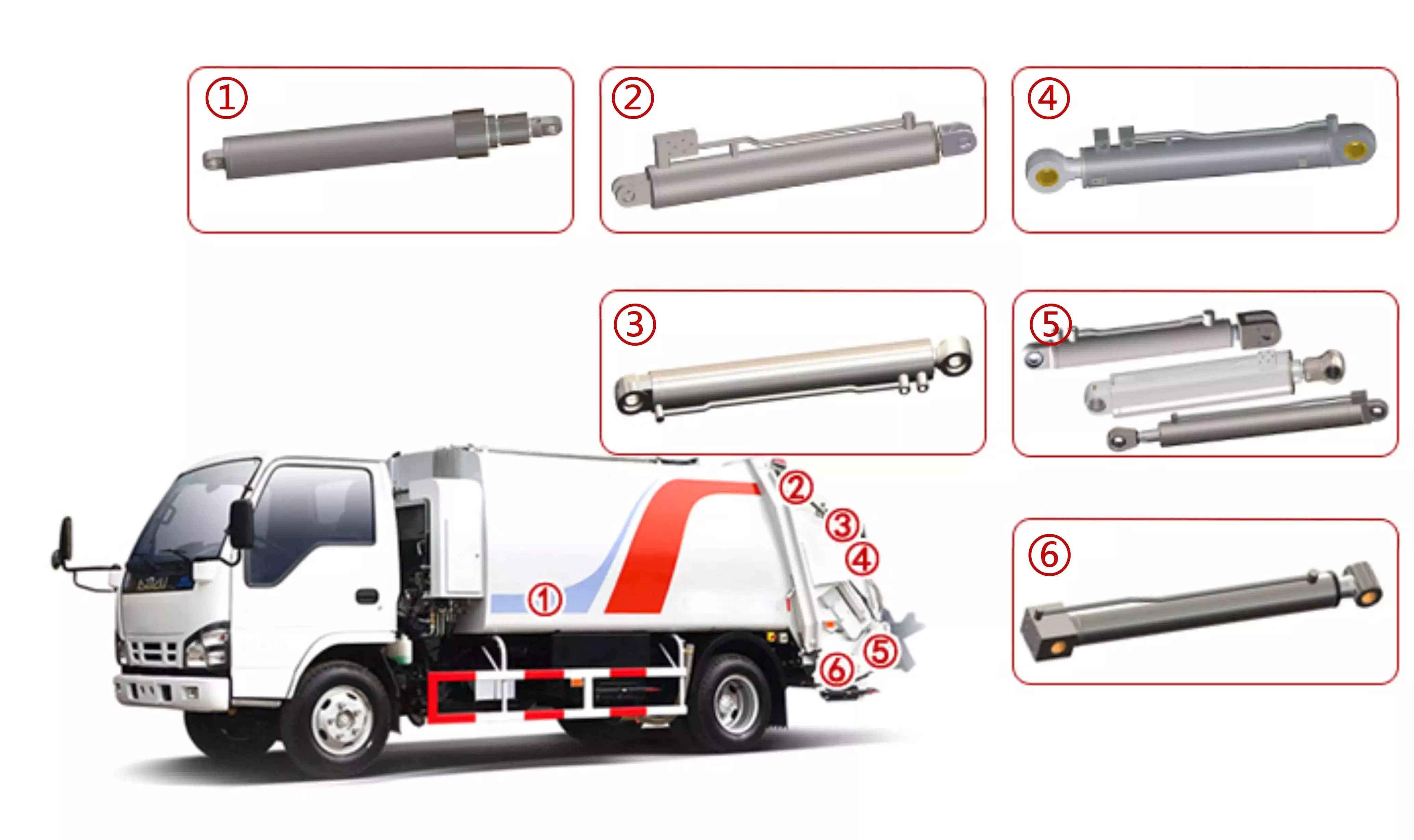
Hydraulic Cylinder used on Front Loader
Hydraulic cylinders are an integral part of many machines and devices, and front loaders are no exception. Front loaders, also known as front end loaders or simply loaders, are heavy equipment machines used for moving, handling, and lifting materials such as dirt, sand, rocks, and other construction debris. The hydraulic cylinder in a front loader is a key component that enables the machine to perform its various functions. It is responsible for lifting the bucket and moving it into position to scoop up material. The hydraulic cylinder also allows the bucket to be lowered and dumped, releasing the material at the desired location. The combination of the hydraulic cylinder and the front loader is a force to be reckoned with. They work together seamlessly, enabling the loader to perform tasks quickly and efficiently. The hydraulic cylinder's strength and precision make it an indispensable part of the front loader, ensuring its smooth operation and reliability.
Hydraulic Cylinder used on Side Loader
The side loader garbage truck is a remarkable piece of engineering, designed with efficiency and hygiene in mind. The truck's unique design, which includes a hydraulic cylinder, allows it to handle large volumes of trash with ease. The hydraulic cylinder in a side loader is made up of 2 main parts: the cylinder tube and the piston. The cylinder tube is a hollow metal cylinder that contains the hydraulic fluid. The piston is a CHINAMFG metal rod that slides within the cylinder tube. The hydraulic cylinder is the driving force behind the side loader garbage truck's capabilities. It powers the lifting and tilting mechanisms that are essential for emptying trash containers into the truck's body. The cylinder uses pressurized hydraulic fluid to generate the force necessary to manipulate the trash container.
Hydraulic Cylinder used on Rear Loader
The rear loader garbage truck is a specialized vehicle designed to handle the collection and disposal of trash in an efficient and hygienic manner. It features a unique loading mechanism that allows trash to be emptied directly into the truck's body from the side, rather than from the rear or top.The hydraulic cylinder is what powers the trash container lifting mechanism. It uses pressurized hydraulic fluid to generate the force needed to tilt and empty the trash container into the truck's hopper. This design allows for quick and effortless emptying, reducing the time and effort needed for trash collection.The hydraulic cylinder in a rear loader must be able to withstand significant forces and pressures, as it is responsible for lifting heavy loads and repeatedly performing this task over time.
About Us
Established in 1988 , HangZhou LD Machinery Co, LTD. (hereinafter referred to "LD") is a leading manufacturer specializing in the design, research, development, manufacture and marketing in the hydraulic industry. Being one of major suppliers of customized components and cylinders for manufacturers spreaded all over the world, the company is committed to offer high quality products with competitive prices and excellent service worldwide.
Headquartered in HangZhou City, ZHangZhoug Province, the company wholly owns a subsidiary production factory named "HangZhou YUEWEI Hydraulic Technology Co., Ltd", which covers an area of more than 380,000 square meters , possesses abundant technical strength and sound production management system, superior machining production equipment, strict and effective quality control system, advanced and excellent inspection instruments.
More than 35 years experience in machining industry, with over 10 experienced technical engineers and 150 skilled workers, LD has a senior engineering technical team with special skills and rich experience in product design, casting, forging, and CNC machining, can handle special material, structure, defect and processing, meet the evolving needs, and provide optimal solution and real one-stop service to customers.
Hydraulic Cylinder Producing Process
Step1: Quality Control on Raw Material
We have our own lab in factory, inspect the raw material and do the test. For every batch of material we received, we will ask supplier provide their certificate, and then cut them to do the test again to see if the results match the certification. Also, every batch we received, we will cut them into pieces to check the air bubbles. Once they are all qualified, we will accept it, and all detail information will be recording in our ERP system. We will also pay lot of attention on the salt spray test for chrome rod. Every month, we will cut the material, put them into test machine to see if it reach the requirement. All the result will be recorded at our QC department. If customer need, we can provide it.
Step2: Quality Control on Machining
we start doing components machining from 1988 with 36 years experience now and insist doing 100% inspection. We spend lots of money, invest on auto robots and machines. Now half of the producing line is by robot so that we can ensure our quality be stable good. For every part of the cylinder, we do 3 times inspecting. Firstly, workers will do self inspection. Secondly, we have tour-hour inspection checking the products, 2 times in the morning and 2 times in the afternoon, make sure that every step is good. After the products are all completed, we will do 100% inspection. For thread, for the tolerance, everything, we need double check. Also, we have specific warehouse just for the measuring tools. Every inspector have their own measuring tool and we will check the measuring tools regularly to make sure they are all in good condition, so that the measuring results will be convincing.
Step3: Quality Control on Welding
We are qualified to AWS certification, which is very popular in North American market. First, for the visual test, we will make sure that every components are welded good, look beautiful. And the second, we need to check the penetration. We have more than 15 years experience, we do know what kind of designing angle can make the cylinder welding strong. Once we finish the first article, we will cut it and analyse the welding to see if it is fulfill the groove. And then do the radiographic testing to make sure there is no gap inside. What's more, we will do the ultrasonic test to check the program for the robot. Now 80% of welding is doing by robot. Once the program confirmed, no 1 can change it unless the welding manager, and they only have 5% right.
Step4: Quality Control on Assembling
For assembling, we have some difference with others. The brand we uses for seals are all those famous brand like Aston, Parker, Hallite. The cylinder we give to our customer has 2 years warranty. For our company, we engrave our part number and manufacturing date for the quality warranty. So no matter for seals or any others, as long as they are parts of cylinder, if it is under 2 years, we will take responsibility for them. And we will do the test for every cylinder like for pressure after we finish assembling.
Step5: Quality Control on Painting
We have our half auto painting line. Right now, we can paint about 1500 cylinders per day, which is about 1 container. Before we do the painting, we will do the wash first and for every cylinder, we will test for hardness, thickness and adhesion to make sure the painting are all good, which will be recorded into OQC report, print out and stick on the box, ship to you with your products.
Step6: Hydraulic Cylinder Packing
For every cylinder, we have the stick to show the detail information like bore size, stroke and working pressure. And we will use individual plastic bag packing. If customer need, we can also use individual carton box packing. We will fasten 1 floor after 1 floor with plat, so customer can only cut what they need and other layer will still be fasten. Moreover, there will be plywood pallet or plywood box for customer choosing. We will also send the loading picture to customer after we ship them to make sure everything is well loaded in China.
Packing Reference
Order Process
Enterprise Features
FAQ
Q1. What is LD product's quality assurance?
100% inspection for each product before shipping with inspection rereport for tracking.
Q2: How long is the warranty on LD products?
The warranty is 2 years for general products since the date of shipment.
Q3: How LD deal with the quality problem during warranty period?
1. LD will take the corresponding cost caused by customer local reparing.
2. LD will provide the product by free if the repair cost is higher than the product value, but the freight involved shall be borne by customer side.
Q4: How to ensure the order can be shipped on time?
LD will send the "production schedule" every week after receiving customers' orders. If any delays, LD will inform customers 3 weeks in advance, so as to facilitate the customer to arrange the schedule.
Q5: Does LD offer delivery service?
Yes. LD has deep cooperation with logistics companies all over the world to provide customers with quick and convenient "Door-to-Door services",including sea, air and express.
Q6: How LD control the product quality?
1. Raw materials: We will test the material of each batch of raw materials we receive, and the piston rod will be tested with salt spray. This is to ensure that the material of our products meets the requirements at the beginning.
2. Processing: We have the leading machining equipment, and obtained ISO9001 certification.
3. Welding: Our factory is equipped with welding robots, and has obtained the AWS certification.
4. Assembly pressure test: 100% testing with OQC report for cHangZhou. The seals we use are: Hallite, Aston and Gapi
/* March 10, 2571 17:59:20 */!function(){function s(e,r){var a,o={};try{e&&e.split(",").forEach(function(e,t){e&&(a=e.match(/(.*?):(.*)$/))&&1
| Certification: | ISO9001 |
|---|---|
| Pressure: | Medium Pressure |
| Work Temperature: | Normal Temperature |
| Acting Way: | Double Acting |
| Working Method: | Straight Trip |
| Adjusted Form: | Regulated Type |
| Samples: |
US$ 299/Piece
1 Piece(Min.Order) | |
|---|
| Customization: |
Available
|
|
|---|
Are there any emerging trends in hydraulic cylinder technology, such as smart features?
Yes, there are several emerging trends in hydraulic cylinder technology, including the integration of smart features. As industries continue to adopt advanced technologies and seek greater efficiency, hydraulic cylinders are being equipped with innovative capabilities to enhance their performance and provide additional benefits. Here are some of the emerging trends in hydraulic cylinder technology:
1. Sensor Integration:
- One of the significant trends in hydraulic cylinder technology is the integration of sensors. Sensors can be embedded within the hydraulic cylinder to monitor various parameters such as pressure, temperature, position, and load. These sensors provide real-time data, allowing for condition monitoring, predictive maintenance, and improved operational control. By collecting and analyzing data, operators can optimize the performance of hydraulic systems, detect potential issues in advance, and prevent failures, resulting in increased reliability and reduced downtime.
2. Connectivity and IoT:
- Hydraulic cylinders are being integrated into the Internet of Things (IoT) ecosystem, enabling connectivity and data exchange. By connecting hydraulic cylinders to a network, operators can remotely monitor and control their performance. IoT-enabled hydraulic cylinders facilitate features such as remote diagnostics, performance optimization, and predictive maintenance. The connectivity aspect allows for better integration with overall equipment systems and enables data-driven decision-making for improved efficiency and productivity.
3. Energy-Efficient Designs:
- With the increasing focus on sustainability and energy efficiency, hydraulic cylinder technology is evolving to incorporate energy-saving features. Manufacturers are developing hydraulic cylinders with improved sealing technologies, reduced friction, and optimized fluid flow dynamics. These advancements minimize energy losses and increase overall system efficiency. Energy-efficient hydraulic cylinders contribute to reduced power consumption, lower operating costs, and a smaller environmental footprint.
4. Advanced Materials and Coatings:
- The use of advanced materials and coatings is another emerging trend in hydraulic cylinder technology. Manufacturers are exploring lightweight materials, such as composites and alloys, to reduce the overall weight of hydraulic cylinders without compromising strength and durability. Furthermore, specialized coatings and surface treatments are being applied to improve corrosion resistance, wear resistance, and lifespan. These advancements enhance the longevity and reliability of hydraulic cylinders, particularly in demanding environments.
5. Intelligent Control Systems:
- Hydraulic cylinder technology is embracing intelligent control systems that optimize performance and enable advanced functionalities. These systems utilize algorithms, machine learning, and artificial intelligence to automate processes, adapt to changing conditions, and optimize hydraulic cylinder movements. Intelligent control systems can adjust parameters in real-time, ensuring precise and efficient operation. This trend allows for increased automation, improved productivity, and enhanced safety in hydraulic system applications.
6. Predictive Maintenance:
- Predictive maintenance is gaining prominence in hydraulic cylinder technology. By utilizing data collected from sensors and monitoring systems, predictive maintenance algorithms can analyze the condition and performance of hydraulic cylinders. This analysis helps to identify potential failures or degradation in advance, enabling proactive maintenance actions. Predictive maintenance reduces unplanned downtime, extends the lifespan of hydraulic cylinders, and optimizes maintenance schedules, resulting in cost savings and improved equipment availability.
7. Enhanced Safety Features:
- Hydraulic cylinder technology is incorporating enhanced safety features to improve operator and equipment safety. These features include integrated safety valves, load monitoring systems, and emergency stop functionalities. Safety systems in hydraulic cylinders help prevent accidents, protect against overloads, and ensure reliable operation. The integration of advanced safety features contributes to safer working environments and compliance with stringent safety regulations.
These emerging trends in hydraulic cylinder technology demonstrate the industry's focus on innovation, performance optimization, and sustainability. The integration of smart features, connectivity, advanced materials, and predictive maintenance capabilities enables hydraulic cylinders to operate more efficiently, provide real-time insights, and enhance overall system performance. As technology continues to advance, hydraulic cylinder technology is expected to evolve further, offering increased functionality and efficiency for various industries and applications.
Impact of Hydraulic Cylinders on Overall Productivity of Manufacturing Operations
Hydraulic cylinders play a crucial role in enhancing the overall productivity of manufacturing operations. These versatile devices are widely used in various industrial applications due to their ability to generate powerful and controlled linear motion. Let's explore how hydraulic cylinders impact the overall productivity of manufacturing operations:
- Powerful Force Generation: Hydraulic cylinders are capable of generating high forces, which enables them to handle heavy loads and perform demanding tasks. By providing the necessary force, hydraulic cylinders facilitate efficient and effective operation of machinery and equipment in manufacturing processes. This ability to exert substantial force contributes to increased productivity by enabling the handling of larger workpieces, enhancing process efficiency, and reducing manual labor requirements.
- Precision and Control: Hydraulic cylinders offer precise control over the movement of loads, allowing for accurate positioning, alignment, and repetitive tasks. The smooth and controlled linear motion provided by hydraulic cylinders ensures precise operation in manufacturing processes, such as assembly, material handling, and machining. This precision and control minimize errors, rework, and scrap, leading to improved productivity and higher-quality output.
- Speed and Efficiency: Hydraulic cylinders can operate at high speeds, enabling rapid movement and cycle times in manufacturing operations. The combination of high force and speed allows for faster operation of machinery and equipment, reducing production cycle times and increasing overall throughput. By optimizing the speed and efficiency of manufacturing processes, hydraulic cylinders contribute to improved productivity and output.
- Flexibility and Adaptability: Hydraulic cylinders are highly flexible and adaptable to different manufacturing applications. They can be customized to meet specific requirements, such as load capacity, stroke length, and mounting options. This versatility allows hydraulic cylinders to be integrated into a wide range of machinery and equipment, accommodating diverse manufacturing needs. The ability to adapt to different tasks and environments enhances overall productivity by enabling efficient utilization of resources and facilitating process optimization.
- Reliability and Durability: Hydraulic cylinders are known for their robustness and durability, making them suitable for demanding manufacturing environments. Their ability to withstand heavy loads, repeated use, and harsh operating conditions ensures reliable performance over extended periods. Minimizing downtime due to cylinder failure or maintenance requirements contributes to increased productivity and uninterrupted manufacturing operations.
In summary, hydraulic cylinders have a significant impact on the overall productivity of manufacturing operations. Their powerful force generation, precision and control, speed and efficiency, flexibility and adaptability, as well as reliability and durability, contribute to optimized processes, increased throughput, improved quality, and reduced labor requirements. By leveraging the capabilities of hydraulic cylinders, manufacturers can enhance productivity, streamline operations, and achieve greater efficiency in their manufacturing processes.
How do hydraulic cylinders accommodate variations in stroke length and force requirements?
Hydraulic cylinders are designed to accommodate variations in stroke length and force requirements, providing flexibility and adaptability for different applications. They can be tailored to meet specific needs by considering factors such as piston diameter, rod diameter, hydraulic pressure, and cylinder design. Here's a detailed explanation of how hydraulic cylinders accommodate variations in stroke length and force requirements:
1. Cylinder Size and Design:
- Hydraulic cylinders come in various sizes and designs to accommodate different stroke lengths and force requirements. The cylinder's diameter, piston area, and rod diameter are key factors that determine the force output. Larger cylinder diameters and piston areas can generate greater force, while smaller diameters are suitable for applications requiring lower force. By selecting the appropriate cylinder size and design, stroke lengths and force requirements can be effectively accommodated.
2. Piston and Rod Configurations:
- Hydraulic cylinders can be designed with different piston and rod configurations to accommodate variations in stroke length. Single-acting cylinders have a single piston and can provide a stroke in one direction. Double-acting cylinders have a piston on both sides, allowing for strokes in both directions. Telescopic cylinders consist of multiple stages that can extend and retract, providing a longer stroke length compared to standard cylinders. By selecting the appropriate piston and rod configuration, the desired stroke length can be achieved.
3. Hydraulic Pressure and Flow:
- The hydraulic pressure and flow rate supplied to the cylinder play a crucial role in accommodating variations in force requirements. Increasing the hydraulic pressure increases the force output of the cylinder, enabling it to handle higher force requirements. By adjusting the pressure and flow rate through hydraulic valves and pumps, the force output can be controlled and matched to the specific requirements of the application.
4. Customization and Tailoring:
- Hydraulic cylinders can be customized and tailored to meet specific stroke length and force requirements. Manufacturers offer a wide range of cylinder sizes, stroke lengths, and force capacities to choose from. Additionally, custom-designed cylinders can be manufactured to suit unique applications with specific stroke length and force demands. By working closely with hydraulic cylinder manufacturers, it is possible to obtain cylinders that precisely match the required stroke length and force requirements.
5. Multiple Cylinders and Synchronization:
- In applications that require high force or longer stroke lengths, multiple hydraulic cylinders can be used in combination. By synchronizing the movement of multiple cylinders through the hydraulic system, the stroke length and force output can be effectively increased. Synchronization can be achieved using mechanical linkages, electronic controls, or hydraulic circuitry, ensuring coordinated movement and force distribution across the cylinders.
6. Load-Sensing and Pressure Control:
- Hydraulic systems can incorporate load-sensing and pressure control mechanisms to accommodate variations in force requirements. Load-sensing systems monitor the load demand and adjust the hydraulic pressure accordingly, ensuring that the cylinder delivers the required force without exerting excessive force. Pressure control valves regulate the pressure within the hydraulic system, allowing for precise control and adjustment of the force output based on the application's needs.
7. Safety Considerations:
- When accommodating variations in stroke length and force requirements, it is essential to consider safety factors. Hydraulic cylinders should be selected and designed with an appropriate safety margin to handle unexpected loads or variations in operating conditions. Safety mechanisms such as overload protection valves and pressure relief valves can be incorporated to prevent damage or failure in situations where the force limits are exceeded.
By considering factors such as cylinder size and design, piston and rod configurations, hydraulic pressure and flow, customization options, synchronization, load-sensing, pressure control, and safety considerations, hydraulic cylinders can effectively accommodate variations in stroke length and force requirements. This flexibility allows hydraulic cylinders to be tailored to meet the specific demands of a wide range of applications, ensuring optimal performance and efficiency.
editor by CX 2024-01-16
China Custom High Quality Hydraulic Cylinder Replacement Cat 336D #3154463 Stick Bucket Hydraulic RAM for Crane, Drilling Rig, Mining Truck, Loader wholesaler
Product Description
Company introduction
HangZhou Roca is a comprehensive manufacturing enterprise engaged in hydraulic cylinders, excavator attachment, metal casting, hydraulic components with certification approval to meet custom or OEM requirements.
ROCA owned factory offers customers effective-cost products with quality assurance. With its professional and experienced R&D team, ROCA Hydraulic devotes itself to research and development to optimize products applied in construction, mining, waster management, forestry, agriculture, etc.
Product introduction
CAT excavator hydraulic cylinder boom, stick (arm) bucket ram CaterpiIIar
| Working temperature | -40°C ~ 80°C |
| Color | RAL9005,Customize |
| Material | CK45,ST52,ST52-3,27SiMn,Customize |
| Seal kit | SKF, Trelleborg, Halite, Chesterton, NOK, Kayaba |
| Piston rod | Hard chromed |
| Packaging | Plywood case |
| Warranty | 12 months |
| Payment | T/T |
Part No.
| CAT 336D | |
| Part Name | Part No. |
| Boom cylinder | 3119517 |
| Stick cylinder | 2836188 |
| DB Family Bucket cylinder | 3154442 |
| TB1 Family Bucket cylinder | 3154463 |
Part size
| CAT 336D | ||
| Boom cylinder - bore | 150mm | 5.91 in |
| Boom cylinder - stroke | 1440mm | 56.7 in |
| Stick cylinder - bore | 170mm | 6.69 in |
| Stick cylinder - stroke | 1738mm | 68.4 in |
| DB Family Bucket cylinder - bore | 150mm | 5.91 in |
| DB Family Bucket cylinder - stroke | 1151mm | 45.3 in |
| TB1 Family Bucket cylinder - bore | 160mm | 6.3 in |
| TB1 Family Bucket cylinder - stroke | 1356mm | 53.4 in |
Hydraulic cylinders are the most effective and efficient method of pushing, pulling, lifting, and lowering.
Nowadays hydraulic cylinders play an essential role in daily application and industry:
√ Mining
√ Earthmoving & Construction
√ Agriculture &Forestry
√Waste Management & Material Handing
√Ship crane & offshore
Selecting the right cylinders for an application is critical in obtaining maximum performance and reliability.
ROCA team takes all your concerns into consideration to suit your hydraulic cylinder requirements.
Together, we work out the best design solution for your application.
FAQ
Q1.Do you have MOQ?
Depending on different ideas, Can be negotiated. The larger the quantity is, the competitive the unit price will be.
Q2.Should the customer pay the delivery fee, How much is it?
For the delivery fee, many samples are being requested to be sent, so we must get the delivery fee.
If you tell me to use the appointed Express, you will give me your express account or you will pay according to the Express.
If you do not request, I will choose a cheap one in China.
Q3.How about the after sale service?
1) We will always keep the quality the same as the buyer's samples and if there is something with the quality, we will make compensation for our customers.
2) We will suggest our packing and take charge in our packing, we will keep the goods safe in the delivery.
3) We will trace the goods from the production to selling, we will solve the problems in the selling for our customers.
Q4.When can I get a price?
We usually quote within 24 hours after we get your inquiry.
Q5: Are you a trade company or manufacturer?
We are a professional manufacturer with our own factory.
The Different Types of Splines in a Splined Shaft
A splined shaft is a machine component with internal and external splines. The splines are formed in 4 different ways: Involute, Parallel, Serrated, and Ball. You can learn more about each type of spline in this article. When choosing a splined shaft, be sure to choose the right 1 for your application. Read on to learn about the different types of splines and how they affect the shaft's performance.
Involute splines
Involute splines in a splined shaft are used to secure and extend mechanical assemblies. They are smooth, inwardly curving grooves that resist separation during operation. A shaft with involute splines is often longer than the shaft itself. This feature allows for more axial movement. This is beneficial for many applications, especially in a gearbox.
The involute spline is a shaped spline, similar to a parallel spline. It is angled and consists of teeth that create a spiral pattern that enables linear and rotatory motion. It is distinguished from other splines by the serrations on its flanks. It also has a flat top. It is a good option for couplers and other applications where angular movement is necessary.
Involute splines are also called involute teeth because of their shape. They are flat on the top and curved on the sides. These teeth can be either internal or external. As a result, involute splines provide greater surface contact, which helps reduce stress and fatigue. Regardless of the shape, involute splines are generally easy to machine and fit.
Involute splines are a type of splines that are used in splined shafts. These splines have different names, depending on their diameters. An example set of designations is for a 32-tooth male spline, a 2,500-tooth module, and a 30 degree pressure angle. An example of a female spline, a fillet root spline, is used to describe the diameter of the splined shaft.
The effective tooth thickness of splines is dependent on the number of keyways and the type of spline. Involute splines in splined shafts should be designed to engage 25 to 50 percent of the spline teeth during the coupling. Involute splines should be able to withstand the load without cracking.
Parallel splines
Parallel splines are formed on a splined shaft by putting 1 or more teeth into another. The male spline is positioned at the center of the female spline. The teeth of the male spline are also parallel to the shaft axis, but a common misalignment causes the splines to roll and tilt. This is common in many industrial applications, and there are a number of ways to improve the performance of splines.
Typically, parallel splines are used to reduce friction in a rotating part. The splines on a splined shaft are narrower on the end face than the interior, which makes them more prone to wear. This type of spline is used in a variety of industries, such as machinery, and it also allows for greater efficiency when transmitting torque.
Involute splines on a splined shaft are the most common. They have equally spaced teeth, and are therefore less likely to crack due to fatigue. They also tend to be easy to cut and fit. However, they are not the best type of spline. It is important to understand the difference between parallel and involute splines before deciding on which spline to use.
The difference between splined and involute splines is the size of the grooves. Involute splines are generally larger than parallel splines. These types of splines provide more torque to the gear teeth and reduce stress during operation. They are also more durable and have a longer life span. And because they are used on farm machinery, they are essential in this type of application.
Serrated splines
A Serrated Splined Shaft has several advantages. This type of shaft is highly adjustable. Its large number of teeth allows large torques, and its shorter tooth width allows for greater adjustment. These features make this type of shaft an ideal choice for applications where accuracy is critical. Listed below are some of the benefits of this type of shaft. These benefits are just a few of the advantages. Learn more about this type of shaft.
The process of hobbing is inexpensive and highly accurate. It is useful for external spline shafts, but is not suitable for internal splines. This type of process forms synchronized shapes on the shaft, reducing the manufacturing cycle and stabilizing the relative phase between spline and thread. It uses a grinding wheel to shape the shaft. CZPT Manufacturing has a large inventory of Serrated Splined Shafts.
The teeth of a Serrated Splined Shaft are designed to engage with the hub over the entire circumference of the shaft. The teeth of the shaft are spaced uniformly around the spline, creating a multiple-tooth point of contact over the entire length of the shaft. The results of these analyses are usually satisfactory. But there are some limitations. To begin with, the splines of the Serrated Splined Shaft should be chosen carefully. If the application requires large-scale analysis, it may be necessary to modify the design.
The splines of the Serrated Splined Shaft are also used for other purposes. They can be used to transmit torque to another device. They also act as an anti-rotational device and function as a linear guide. Both the design and the type of splines determine the function of the Splined Shaft. In the automobile industry, they are used in vehicles, aerospace, earth-moving machinery, and many other industries.
Ball splines
The invention relates to a ball-spinned shaft. The shaft comprises a plurality of balls that are arranged in a series and are operatively coupled to a load path section. The balls are capable of rolling endlessly along the path. This invention also relates to a ball bearing. Here, a ball bearing is 1 of the many types of gears. The following discussion describes the features of a ball bearing.
A ball-splined shaft assembly comprises a shaft with at least 1 ball-spline groove and a plurality of circumferential step grooves. The shaft is held in a first holding means that extends longitudinally and is rotatably held by a second holding means. Both the shaft and the first holding means are driven relative to 1 another by a first driving means. It is possible to manufacture a ball-splined shaft in a variety of ways.
A ball-splined shaft features a nut with recirculating balls. The ball-splined nut rides in these grooves to provide linear motion while preventing rotation. A splined shaft with a nut that has recirculating balls can also provide rotary motion. A ball splined shaft also has higher load capacities than a ball bushing. For these reasons, ball splines are an excellent choice for many applications.
In this invention, a pair of ball-spinned shafts are housed in a box under a carrier device 40. Each of the 2 shafts extends along a longitudinal line of arm 50. One end of each shaft is supported rotatably by a slide block 56. The slide block also has a support arm 58 that supports the center arm 50 in a cantilever fashion.
Sector no-go gage
A no-go gauge is a tool that checks the splined shaft for oversize. It is an effective way to determine the oversize condition of a splined shaft without removing the shaft. It measures external splines and serrations. The no-go gage is available in sizes ranging from 19mm to 130mm with a 25mm profile length.
The sector no-go gage has 2 groups of diametrally opposed teeth. The space between them is manufactured to a maximum space width and the tooth thickness must be within a predetermined tolerance. This gage would be out of tolerance if the splines were measured with a pin. The dimensions of this splined shaft can be found in the respective ANSI or DIN standards.
The go-no-go gage is useful for final inspection of thread pitch diameter. It is also useful for splined shafts and threaded nuts. The thread of a screw must match the contour of the go-no-go gage head to avoid a no-go condition. There is no substitute for a quality machine. It is an essential tool for any splined shaft and fastener manufacturer.
The NO-GO gage can detect changes in tooth thickness. It can be calibrated under ISO17025 standards and has many advantages over a non-go gage. It also gives a visual reference of the thickness of a splined shaft. When the teeth match, the shaft is considered ready for installation. It is a critical process. In some cases, it is impossible to determine the precise length of the shaft spline.
The 45-degree pressure angle is most commonly used for axles and torque-delivering members. This pressure angle is the most economical in terms of tool life, but the splines will not roll neatly like a 30 degree angle. The 45-degree spline is more likely to fall off larger than the other two. Oftentimes, it will also have a crowned look. The 37.5 degree pressure angle is a compromise between the other 2 pressure angles. It is often used when the splined shaft material is harder than usual.


China OEM Wind Solar CZPT Band Saw Robot Snow Removal Tow Pallet Truck Use Double Action Hsg Piston CZPT CZPT CZPT Hercules Hydraulic RAM Cylinder Manufacturer with Free Design Custom
Product Description
small piston double acting hydraulic lift ram cylinder
Product Description
Eaton, parker, hercules, prince, cross type double acting hydraulic cylinder are used for Trailer, Agricultural Machinery, Garbage Truck, Landing Platform etc.
Tsingshi hydraulic Customers, MAN, JAC, VOLVO, SHACMAN, DAF, JMC, HUNO, CIMC, SINOTRUK, TATRA,BENS,XIHU (WEST LAKE) DIS.FENG, FOTON,etc.
1.Piston rod electroplate hard chrome;
2.lighter and easier to maintenance double acting hydraulic cylinder;
3.High quality alloy seamless steel pipe have better mechanical properties;
4.The world famous brands of seals, such as Parker, Merkel, Hallite, Kaden, etc;
5.World-class processing technology ensures stable and reliable quality.
| NO | ITEM | double acting hydraulic cylinder DATA |
| 1 | Material | Carbon Steel, Alloy Steel, 27SiMn,45#,20#,etc |
| 2 | Honed tube | 40-300mm, Heat treatment, honing, rolling |
| 3 | Honed tube | 30-280mm, plated nickel or hard Chrome or ceramic |
| 4 | Seal kit | Parker, Merkel, Hallite, Kaden, etc |
| 5 | Coating | Sandblasting, primer paint, middle paint, finish paint, Color can paint according to customer demands. |
| 6 | Technology | double acting hydraulic cylinder |
| 7 | Mounting type | Pin-eye , flange, trunnion mount,ball mount, screw thread. FC, FE, FEE, FSE,TPIN |
| 8 | Working medium | Hydraulic Oil |
| 9 | Working pressure | 16-20Mpa hydraulic lift cylinder |
| 10 | Temperature range | -50°C to +100°C |
Detailed Photos
Company Profile
Tsingshi hydraulic is a hydraulic telescopic cylinder for dump tipper truck company which takes up with hydraulic design, R&D, manufacturer, sell and service hydraulic products-small piston double acting hydraulic lift ram oil cylinder.
-double acting hydraulic cylinder Certification ISO9001 TS16949, etc;
-mini double acting hydraulic cylinder Export to North America, South America, Australia, South Korea, Southeast Asia, South Africa, Europe, Middle East, etc;
-ODM&OEM small double acting hydraulic cylinder according to client's requirements;
-Professional manufacturer& supplier of Hydraulic Cylinders over 30 years;
-The micro double acting hydraulic cylinder can be used for Dump Truck, Tipper Truck, Trailer, Agricultural Machinery, Garbage Truck,Landing Platform etc; We can produce the follow brand hydraulic cylinder. HYVA, BINOTTO, EDBRO, PENTA, MAILHOT, CUSTOM HOIST, MUNCIE, METARIS, HYDRAULEX GLOBAL, HYCO, PARKER, COMMERCIAL HYDRAULICS, MEILLER. WTJX, XT, JX, HCIC, ZX, SZ, SJ.
CUSTOMERS PHOTOS
QUALITY GUARANTEE
HIGH QUALITITY GUARANTEE-double acting hydraulic cylinder
-7*24 service.
-Competitive price.
-Professional technical team.
-Perfect after-sales service system.
-ODM&OEM Hydraulic Cylinder according to customer needs.
-Strong Hydraulic Cylinder production capacity to ensure fast delivery.
-Guarantee Quality. Every process must be inspected, all products need be tested before leaving the factory.
<hydraulic cylinder Leak Test
<piston hydraulic cylinder Buffer Test
<hydraulic lift cylinder Reliability Test
<hydraulic ram cylinder Full Stroke Test
<hydraulic cylinder double acting Operation Test
<micro double acting hydraulic cylinder Pressure Tight Test
<small double acting hydraulic cylinder Load Efficiency Test
<double action hydraulic cylinder Start-up Pressure Test
<double acting hydraulic cylinder Testing the Effect of Limit
SALES AND SERVICE
PRODUCTS SERIES
ONE WORLD ONE LOVE
Ball Screws - Dimensions, Applications, and Benefits
Ball screws are popular, lightweight, precision mechanical components. They are commonly used in machinery, gears, and knurled objects. These screw-like parts can be easily maintained and lubricated using oil. This article discusses their dimensions, applications, and benefits. The following sections provide additional information to help you select the right ball screw for your needs. We'll discuss some of the important characteristics of ball screws and what makes them so useful.
Preloading
A key problem with nut-to-ball screw backlash is the ability of the nut to move freely on the threads of the ball screw. To solve this problem, a patented solution was developed. The patent, 4,557,156, describes an innovative method for preloading ball screws and nuts. By applying a preloading nut, the threads of the ball screw are prevented from moving back and forth with the nut.
A mechanical design that involves axial play involves a lot of mass, inertia, and complexity. These characteristics lead to wear and rust problems. Preloading ball screws using a dynamic system reduces mechanical complexity by allowing preload to be adjusted while the mechanism is running. This also reduces the number of mechanical parts and simplifies manufacturing. Thus, the preloading method of the present invention is advantageous.
The servo motors used in the system monitor the output torque and adjust the power to 1 motor in a dynamic way, thus creating a torque differential between the balls. This torque differential in turn creates a preload force between the ball nuts. The servo motors' output torque is controlled in this manner, and the machine's backlash clearance can be precisely controlled. Hence, the machine can perform multiple tasks with increased precision.
Several prior art methods for preloading ball screws are described in detail in FIG. 3. The helical thread grooves of the ball screw 26 and the nut 24 define a pathway for roller balls to travel along. The stylized broken line indicates the general position of the axis of the ball roller screw 26. The corresponding ball screws are used in a number of applications. This technique may be used to manufacture custom-sized screws.
Lubrication
Ball screws are mechanical elements that roll balls through a groove. Improper lubrication can reduce the life of these screw elements. Improper lubrication can lead to shaft damage, malfunction, and decreased performance. This article discusses the importance of proper lubrication and how to do it. You can learn how to properly lubricate ball screws in the following paragraphs. Here are some tips to ensure long-term performance and safety of ball screws.
The first thing you should do is determine the type of lubricant you'll be using. Oils are preferred because they tend to remain inside the ball nut, and grease can build up in it. Oils also tend to have better anti-corrosion properties than grease. However, grease is more likely to be clogged with debris than oils. So, before you choose the lubricant that's right for your screw, make sure you wash it off.
The oil used in ball screw lubrication must be applied at a controlled rate. It can prevent metal-on-metal contact and clean out contaminants as it passes through the ball nut. However, oil as a lubricant is expensive and can contaminate the process if it mixes with the cutting fluid. Grease, on the other hand, is inexpensive, requires fewer applications, and does not contaminate process fluids.
If you use a synthetic oil for lubrication, make sure to choose a viscosity that is appropriate for the operating temperature. Oil viscosity can increase the temperature of the ball screw assembly, and excessive oil can reduce its life. A correct amount of oil will reduce the temperature of the ball screw assembly, while too little will increase friction and wear. Use the following guidelines to determine the right amount of oil for your screw.
Dimensions
Dimensions of ball screws are a very important aspect to consider when determining the best type for your application. Technical acceptance conditions for ball screws specify the allowed deviations during acceptance tests. The tolerance class can also change, depending on the needs of a specific application. The following table lists the most important tolerance values for the full range of screw lengths. This table is a helpful guide when looking for a specific screw. The table below lists the dimensions of common ball screws.
The axial load applied to a ball screw is 0.5 x Fpr / 2Fpr. The minimum screw diameter is known as the root diameter. The axial load causes the screw shaft to deform in a certain way (DL1 and DL2). The elastic deflection induced by the load on a ball screw is called its rigidity. This rigidity is important for calculating sizing parameters for a ball screw.
The preload value of the ball screw affects the dynamic load capacity. A preload of 10 percent is considered adequate, while a value greater than this may compromise the screw's durability. In general, a high preload value will result in a lower dynamic load capacity and greater wear. However, the preload value must be calculated with the relevant screw parameters. This is because a high preload value reduces the screw's durability.
To ensure that your screw meets the specified parameters, the dynamic load capacity must be calculated. This is the amount of force a ball screw will withstand under a specified load. This calculation also includes strength checks. If you are using a ball screw for applications that need extra strength, it may require a safety factor. For example, if the screw is used for double-axial mounting, then the outer ball nut must be inserted into the nut, causing a secondary load.
Applications
The present invention provides a simple, yet highly effective way to mount a ball screw. Its absence of insert slots or through holes makes it simpler to assemble and provides a more uniform nut. The lack of mechanical features also reduces heat treatment issues, and the nut's hardness can be uniformly hardened. As a result, the screw's overall performance is improved. Here are some examples of applications for ball screws.
Preloading is the process of applying force to a ball screw. This increases the rigidity of the screw assembly and eliminates backlash, which is lost motion caused by clearance between the nut and ball. Backlash disrupts repeatability and accuracy. Spacer preloading involves inserting force between 2 ball nuts and transmitting it through the grooves. This method is ideal when preloading is needed in large quantities. In addition to increasing rigidity, preloading can improve accuracy.
Ball screws require careful care in their working surfaces to prevent contamination. Rubber or leather bellows can be used to protect their surfaces, while positive air pressure can be applied to the screw. Preloading eliminates backlash, a common problem among screw assemblies. In addition to the numerous applications for ball screws, they are also critical to computer-controlled motion-control systems and wire bonding. And there are many more examples. So what are the benefits of using these devices?
The spring preloading system uses a spring in between 2 ball nuts, applying tensional forces to the ball nuts. This spring creates grooves in the nut's middle, which facilitates recirculation of the balls. The spring preloading mechanism is more compact than the double nut mechanism, but the lengthening of the lead reduces the ball screw's load capacity. Its compact design makes it ideal for small clearance assemblies.
Maintenance
In addition to performing maintenance tasks yourself, the manufacturer of ball screws should offer reverse engineering services that will enable them to identify specific problems. The process of reverse engineering allows ball screw manufacturers to develop new ball screws and parts. In the event that a ball screw is beyond repair, a manufacturer can often save a significant amount of money by repairing it instead of replacing it. In addition to repairing a ball screw, the manufacturer should also offer free evaluation services for the component. Reconditioning and replacement involve the use of new parts, while reloading and replacement replace the screw.
Performing routine maintenance checks on ball screw assemblies is essential for maintaining optimal performance and extending their service life. Overtime, excessive wear can lead to a variety of problems, including backlash, vibration, and ball bearing noise. In addition, the increased friction increases the required torque for turning a screw, causing system failure and significant downtime. To ensure that a ball screw is fully functional, it must be checked for wear and maintain the proper lubrication system.
Discoloration or pitting on a ball screw indicates that it is in need of repair. The same is true if there are chatter marks in the ball groove. Oftentimes, a ball screw needs a new lubrication seal or wipers. Additionally, it may be missing or over-wearing, which could result in permanent failure. Finally, excessive power draw could be a sign of improper lubrication or improper installation.
Proper maintenance is essential for any machine tool. When performed properly, machine tools can last decades with continuous use. Proper care and maintenance is essential to ensure long life and optimal performance. In addition to improving machine tool uptime, proper maintenance affects the accuracy and repeatability of the end product. Therefore, premium machine tool manufacturers focus on the performance and durability of ball screws. They develop innovative designs and lubricants to optimize the lifespan of their products.
China Best Sales Roundline Small Piston Hydraulic RAM Oil Hydraulic Cylinder near me factory
Product Description
1.All cylinder in this series use carbon streel for both front/rear cover.
2.strong structure.
3.Medium carbon steel S45C is used for the piston rod,with hard chromate plated then polished to mirror class . lt has very high rigidity and resistance to erosion and corrosion.
4.The cylinder is mode by honed carbon steel tube.
5.Adjustable cushions and bleeding holes at both ends.
Specification
| Cylinder bore | 32,40,50,63,80,100,125,150,200,250,300 |
| Tatal Stroke | 10~1000 |
| Maximum use pressure | 350kgf/cm |
| Minimum use pressure | 3kgf/cm |
| Actuation oil | ISO Vg68 |
| Speed range | 8~400 mm/s |
| Operating temperature range | -10~+200ºC |
How to order
| Broe | Φ32,Φ40,Φ50,Φ63,Φ80,Φ100,Φ125,Φ150 |
| Semsomh device(magnetic) | with magnetic,without magnetic |
| Stroke | 20~2000mm |
| Mounting accessories |
basic type,Front flange mounting,front foot mounting, center trunnion mounting,single swivel mounting,double swivel mounting |
| Rod accessories | i type rod clevis,y type rod clevis |
| Oil port location | custom made |
Contact us to support customization
Packaging & Delivery
About Us
Youjiaxin is an experienced manufacturer specializes in CNC machining, CNC turning, stamping and laser cutting parts with different materials and many finished surface.
We are in the business of providing value-added services to assist you in completing your projects. The high quality and reliability of our service has enabled us to maintain long-standing relationships with our clients in various industries.
Rich experience, engineering expertise and high performance equipment help us in offering our customers top quality products.
If you have any question, please kindly refer to the FAQs below or contact us directly.
FAQ
- Do you accept OEM manufacturing?
Yes! We do accept OEM manufacturing. so we can provide the best price as well as the first class service. - Could we get small quantity samples?
Yes! We understand the quality test is important and we are glad to make the sample for you. The MOQ could be 1pcs. - Can you provide free sample? How long can we expect to get the sample?
Sample can be free of charge if deposit for future order received. samples need 5-10days if need custom make . standard can be ship out in 2 days. - How long is the production time?
Normally about 30 days. - What is the warranty?
1year against B/L date.
How to Select a Worm Shaft and Gear For Your Project
You will learn about axial pitch PX and tooth parameters for a Worm Shaft 20 and Gear 22. Detailed information on these 2 components will help you select a suitable Worm Shaft. Read on to learn more....and get your hands on the most advanced gearbox ever created! Here are some tips for selecting a Worm Shaft and Gear for your project!...and a few things to keep in mind.
Gear 22
The tooth profile of Gear 22 on Worm Shaft 20 differs from that of a conventional gear. This is because the teeth of Gear 22 are concave, allowing for better interaction with the threads of the worm shaft 20. The worm's lead angle causes the worm to self-lock, preventing reverse motion. However, this self-locking mechanism is not entirely dependable. Worm gears are used in numerous industrial applications, from elevators to fishing reels and automotive power steering.
The new gear is installed on a shaft that is secured in an oil seal. To install a new gear, you first need to remove the old gear. Next, you need to unscrew the 2 bolts that hold the gear onto the shaft. Next, you should remove the bearing carrier from the output shaft. Once the worm gear is removed, you need to unscrew the retaining ring. After that, install the bearing cones and the shaft spacer. Make sure that the shaft is tightened properly, but do not over-tighten the plug.
To prevent premature failures, use the right lubricant for the type of worm gear. A high viscosity oil is required for the sliding action of worm gears. In two-thirds of applications, lubricants were insufficient. If the worm is lightly loaded, a low-viscosity oil may be sufficient. Otherwise, a high-viscosity oil is necessary to keep the worm gears in good condition.
Another option is to vary the number of teeth around the gear 22 to reduce the output shaft's speed. This can be done by setting a specific ratio (for example, 5 or 10 times the motor's speed) and modifying the worm's dedendum accordingly. This process will reduce the output shaft's speed to the desired level. The worm's dedendum should be adapted to the desired axial pitch.
Worm Shaft 20
When selecting a worm gear, consider the following things to consider. These are high-performance, low-noise gears. They are durable, low-temperature, and long-lasting. Worm gears are widely used in numerous industries and have numerous benefits. Listed below are just some of their benefits. Read on for more information. Worm gears can be difficult to maintain, but with proper maintenance, they can be very reliable.
The worm shaft is configured to be supported in a frame 24. The size of the frame 24 is determined by the center distance between the worm shaft 20 and the output shaft 16. The worm shaft and gear 22 may not come in contact or interfere with 1 another if they are not configured properly. For these reasons, proper assembly is essential. However, if the worm shaft 20 is not properly installed, the assembly will not function.
Another important consideration is the worm material. Some worm gears have brass wheels, which may cause corrosion in the worm. In addition, sulfur-phosphorous EP gear oil activates on the brass wheel. These materials can cause significant loss of load surface. Worm gears should be installed with high-quality lubricant to prevent these problems. There is also a need to choose a material that is high-viscosity and has low friction.
Speed reducers can include many different worm shafts, and each speed reducer will require different ratios. In this case, the speed reducer manufacturer can provide different worm shafts with different thread patterns. The different thread patterns will correspond to different gear ratios. Regardless of the gear ratio, each worm shaft is manufactured from a blank with the desired thread. It will not be difficult to find 1 that fits your needs.
Gear 22's axial pitch PX
The axial pitch of a worm gear is calculated by using the nominal center distance and the Addendum Factor, a constant. The Center Distance is the distance from the center of the gear to the worm wheel. The worm wheel pitch is also called the worm pitch. Both the dimension and the pitch diameter are taken into consideration when calculating the axial pitch PX for a Gear 22.
The axial pitch, or lead angle, of a worm gear determines how effective it is. The higher the lead angle, the less efficient the gear. Lead angles are directly related to the worm gear's load capacity. In particular, the angle of the lead is proportional to the length of the stress area on the worm wheel teeth. A worm gear's load capacity is directly proportional to the amount of root bending stress introduced by cantilever action. A worm with a lead angle of g is almost identical to a helical gear with a helix angle of 90 deg.
In the present invention, an improved method of manufacturing worm shafts is described. The method entails determining the desired axial pitch PX for each reduction ratio and frame size. The axial pitch is established by a method of manufacturing a worm shaft that has a thread that corresponds to the desired gear ratio. A gear is a rotating assembly of parts that are made up of teeth and a worm.
In addition to the axial pitch, a worm gear's shaft can also be made from different materials. The material used for the gear's worms is an important consideration in its selection. Worm gears are usually made of steel, which is stronger and corrosion-resistant than other materials. They also require lubrication and may have ground teeth to reduce friction. In addition, worm gears are often quieter than other gears.
Gear 22's tooth parameters
A study of Gear 22's tooth parameters revealed that the worm shaft's deflection depends on various factors. The parameters of the worm gear were varied to account for the worm gear size, pressure angle, and size factor. In addition, the number of worm threads was changed. These parameters are varied based on the ISO/TS 14521 reference gear. This study validates the developed numerical calculation model using experimental results from Lutz and FEM calculations of worm gear shafts.
Using the results from the Lutz test, we can obtain the deflection of the worm shaft using the calculation method of ISO/TS 14521 and DIN 3996. The calculation of the bending diameter of a worm shaft according to the formulas given in AGMA 6022 and DIN 3996 show a good correlation with test results. However, the calculation of the worm shaft using the root diameter of the worm uses a different parameter to calculate the equivalent bending diameter.
The bending stiffness of a worm shaft is calculated through a finite element model (FEM). Using a FEM simulation, the deflection of a worm shaft can be calculated from its toothing parameters. The deflection can be considered for a complete gearbox system as stiffness of the worm toothing is considered. And finally, based on this study, a correction factor is developed.
For an ideal worm gear, the number of thread starts is proportional to the size of the worm. The worm's diameter and toothing factor are calculated from Equation 9, which is a formula for the worm gear's root inertia. The distance between the main axes and the worm shaft is determined by Equation 14.
Gear 22's deflection
To study the effect of toothing parameters on the deflection of a worm shaft, we used a finite element method. The parameters considered are tooth height, pressure angle, size factor, and number of worm threads. Each of these parameters has a different influence on worm shaft bending. Table 1 shows the parameter variations for a reference gear (Gear 22) and a different toothing model. The worm gear size and number of threads determine the deflection of the worm shaft.
The calculation method of ISO/TS 14521 is based on the boundary conditions of the Lutz test setup. This method calculates the deflection of the worm shaft using the finite element method. The experimentally measured shafts were compared to the simulation results. The test results and the correction factor were compared to verify that the calculated deflection is comparable to the measured deflection.
The FEM analysis indicates the effect of tooth parameters on worm shaft bending. Gear 22's deflection on Worm Shaft can be explained by the ratio of tooth force to mass. The ratio of worm tooth force to mass determines the torque. The ratio between the 2 parameters is the rotational speed. The ratio of worm gear tooth forces to worm shaft mass determines the deflection of worm gears. The deflection of a worm gear has an impact on worm shaft bending capacity, efficiency, and NVH. The continuous development of power density has been achieved through advancements in bronze materials, lubricants, and manufacturing quality.
The main axes of moment of inertia are indicated with the letters A-N. The three-dimensional graphs are identical for the seven-threaded and one-threaded worms. The diagrams also show the axial profiles of each gear. In addition, the main axes of moment of inertia are indicated by a white cross.
China supplier Cat 330c Excavator Cylinder Hydraulic Stick Bucket RAM Type Hydraulic Cylinder for Cat with Good quality
Product Description
Company introduction
HangZhou Roca is a comprehensive manufacturing enterprise engaged in hydraulic cylinders, excavator attachment, metal casting, hydraulic components with certification approval to meet custom or OEM requirements.
ROCA owned factory offers customers effective-cost products with quality assurance. With its professional and experienced R&D team, ROCA Hydraulic devotes itself to research and development to optimize products applied in construction, mining, waste management, forestry, agriculture, etc.
Product introduction
CAT excavator hydraulic cylinder Cat
| Working temperature | -40°C ~ 80°C |
| Color | RAL9005,Customize |
| Material | CK45,ST52,ST52-3,27SiMn,Customize |
| Seal kit | Trelleborg, Halite, Chesterton, NOK, Kayaba |
| Piston rod | Hard chromed |
| Packaging | Plywood case |
| Warranty | 12 months |
| Payment | T/T |
Part No.
| CAT 330C | |
| Part Name | Part No. |
| Boom cylinder | 1915548 |
| Stick cylinder | 1915551 |
| D family Bucket cylinder | 1772465 |
| E family Bucket cylinder | 1915554 |
Part size
| CAT 330C | ||
| Boom cylinder - bore | 150 mm | 5.91 in |
| Boom cylinder - rod | 105 mm | 4.13 in |
| Boom cylinder - stroke | 1440 mm | 57 in |
| Stick cylinder - bore | 170 mm | 6.69 in |
| Stick cylinder - rod | 115 mm | 4.53 in |
| Stick cylinder - stroke | 1738 mm | 68 in |
| D family Bucket cylinder - bore | 150 mm | 5.91 in |
| D family Bucket cylinder - rod | 105 mm | 4.13 |
| D family Bucket cylinder - stroke | 1156 mm | 45.51in |
| E family Bucket cylinder - bore | 160 mm | 6.3 in |
| E family Bucket cylinder - rod | 110 mm | 4.33 in |
| E family Bucket cylinder - stroke | 1356 mm | 53 in |
Hydraulic cylinders are the most effective and efficient method of pushing, pulling, lifting, and lowering.
Nowadays hydraulic cylinders play an essential role in daily application and industry:
√ Mining
√ Earthmoving & Construction
√ Agriculture &Forestry
√Waste Management & Material Handing
√Ship crane & offshore
Selecting the right cylinders for an application is critical in obtaining maximum performance and reliability.
ROCA team takes all your concerns into consideration to suit your hydraulic cylinder requirements.
Together, we work out the best design solution for your application.
FAQ
Q1.Do you have MOQ?
Depending on different ideas, Can be negotiated. The larger the quantity is, the competitive the unit price will be.
Q2.Should the customer pay the delivery fee, How much is it?
For the delivery fee, many samples are being requested to be sent, so we must get the delivery fee.
If you tell me to use the appointed Express, you will give me your express account or you will pay according to the Express.
If you do not request, I will choose a cheap one in China.
Q3.How about the after sale service?
1) We will always keep the quality the same as the buyer's samples and if there is something with the quality, we will make compensation for our customers.
2) We will suggest our packing and take charge in our packing, we will keep the goods safe in the delivery.
3) We will trace the goods from the production to selling, we will solve the problems in the selling for our customers.
Q4.When can I get a price?
We usually quote within 24 hours after we get your inquiry.
Q5: Are you a trade company or manufacturer?
We are a professional manufacturer with our own factory.
The Benefits of Spline Couplings for Disc Brake Mounting Interfaces
Spline couplings are commonly used for securing disc brake mounting interfaces. Spline couplings are often used in high-performance vehicles, aeronautics, and many other applications. However, the mechanical benefits of splines are not immediately obvious. Listed below are the benefits of spline couplings. We'll discuss what these advantages mean for you. Read on to discover how these couplings work.
Disc brake mounting interfaces are splined
There are 2 common disc brake mounting interfaces - splined and six-bolt. Splined rotors fit on splined hubs; six-bolt rotors will need an adapter to fit on six-bolt hubs. The six-bolt method is easier to maintain and may be preferred by many cyclists. If you're thinking of installing a disc brake system, it is important to know how to choose the right splined and center lock interfaces.
Aerospace applications
The splines used for spline coupling in aircraft are highly complex. While some previous researches have addressed the design of splines, few publications have tackled the problem of misaligned spline coupling. Nevertheless, the accurate results we obtained were obtained using dedicated simulation tools, which are not commercially available. Nevertheless, such tools can provide a useful reference for our approach. It would be beneficial if designers could use simple tools for evaluating contact pressure peaks. Our analytical approach makes it possible to find answers to such questions.
The design of a spline coupling for aerospace applications must be accurate to minimize weight and prevent failure mechanisms. In addition to weight reduction, it is necessary to minimize fretting fatigue. The pressure distribution on the spline coupling teeth is a significant factor in determining its fretting fatigue. Therefore, we use analytical and experimental methods to examine the contact pressure distribution in the axial direction of spline couplings.
The teeth of a spline coupling can be categorized by the type of engagement they provide. This study investigates the position of resultant contact forces in the teeth of a spline coupling when applied to pitch diameter. Using FEM models, numerical results are generated for nominal and parallel offset misalignments. The axial tooth profile determines the behavior of the coupling component and its ability to resist wear. Angular misalignment is also a concern, causing misalignment.
In order to assess wear damage of a spline coupling, we must take into consideration the impact of fretting on the components. This wear is caused by relative motion between the teeth that engage them. The misalignment may be caused by vibrations, cyclical tooth deflection, or angular misalignment. The result of this analysis may help designers improve their spline coupling designs and develop improved performance.
CZPT polyimide, an abrasion-resistant polymer, is a popular choice for high-temperature spline couplings. This material reduces friction and wear, provides a low friction surface, and has a low wear rate. Furthermore, it offers up to 50 times the life of metal on metal spline connections. For these reasons, it is important to choose the right material for your spline coupling.
High-performance vehicles
A spline coupler is a device used to connect splined shafts. A typical spline coupler resembles a short pipe with splines on either end. There are 2 basic types of spline coupling: single and dual spline. One type attaches to a drive shaft, while the other attaches to the gearbox. While spline couplings are typically used in racing, they're also used for performance problems.
The key challenge in spline couplings is to determine the optimal dimension of spline joints. This is difficult because no commercial codes allow the simulation of misaligned joints, which can destroy components. This article presents analytical approaches to estimating contact pressures in spline connections. The results are comparable with numerical approaches but require special codes to accurately model the coupling operation. This research highlights several important issues and aims to make the application of spline couplings in high-performance vehicles easier.
The stiffness of spline assemblies can be calculated using tooth-like structures. Such splines can be incorporated into the spline joint to produce global stiffness for torsional vibration analysis. Bearing reactions are calculated for a certain level of misalignment. This information can be used to design bearing dimensions and correct misalignment. There are 3 types of spline couplings.
Major diameter fit splines are made with tightly controlled outside diameters. This close fit provides concentricity transfer from the male to the female spline. The teeth of the male spline usually have chamfered tips and clearance with fillet radii. These splines are often manufactured from billet steel or aluminum. These materials are renowned for their strength and uniform grain created by the forging process. ANSI and DIN design manuals define classes of fit.
Disc brake mounting interfaces
A spline coupling for disc brake mounting interfaces is a type of hub-to-brake-disc mount. It is a highly durable coupling mechanism that reduces heat transfer from the disc to the axle hub. The mounting arrangement also isolates the axle hub from direct contact with the disc. It is also designed to minimize the amount of vehicle downtime and maintenance required to maintain proper alignment.
Disc brakes typically have substantial metal-to-metal contact with axle hub splines. The discs are held in place on the hub by intermediate inserts. This metal-to-metal contact also aids in the transfer of brake heat from the brake disc to the axle hub. Spline coupling for disc brake mounting interfaces comprises a mounting ring that is either a threaded or non-threaded spline.
During drag brake experiments, perforated friction blocks filled with various additive materials are introduced. The materials included include Cu-based powder metallurgy material, a composite material, and a Mn-Cu damping alloy. The filling material affects the braking interface's wear behavior and friction-induced vibration characteristics. Different filling materials produce different types of wear debris and have different wear evolutions. They also differ in their surface morphology.
Disc brake couplings are usually made of 2 different types. The plain and HD versions are interchangeable. The plain version is the simplest to install, while the HD version has multiple components. The two-piece couplings are often installed at the same time, but with different mounting interfaces. You should make sure to purchase the appropriate coupling for your vehicle. These interfaces are a vital component of your vehicle and must be installed correctly for proper operation.
Disc brakes use disc-to-hub elements that help locate the forces and displace them to the rim. These elements are typically made of stainless steel, which increases the cost of manufacturing the disc brake mounting interface. Despite their benefits, however, the high braking force loads they endure are hard on the materials. Moreover, excessive heat transferred to the intermediate elements can adversely affect the fatigue life and long-term strength of the brake system.