Product Description
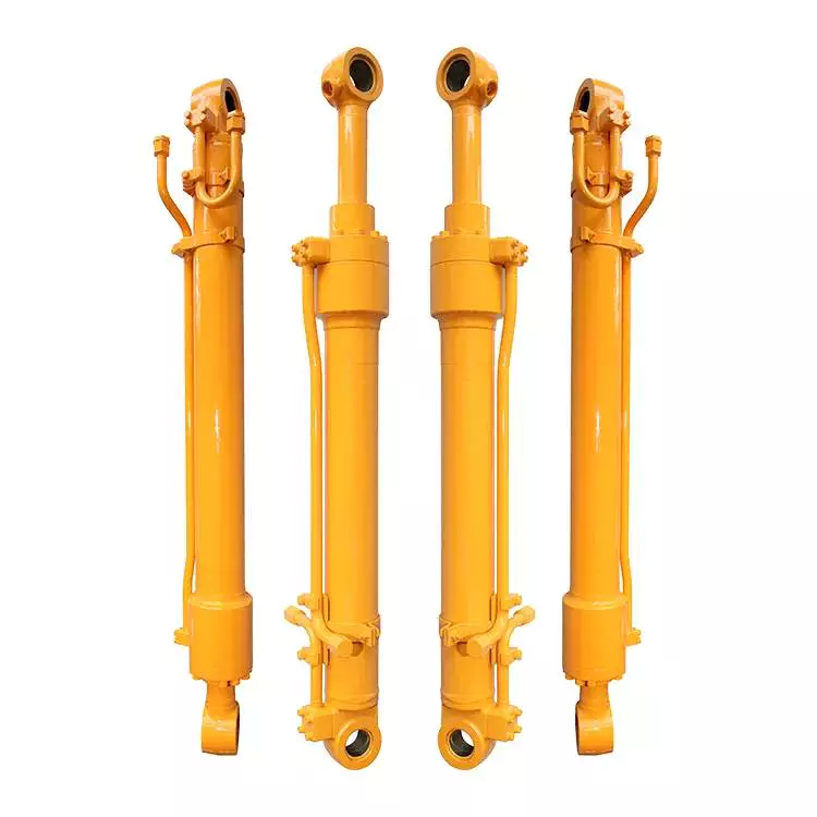
Master Hydraulic Cylinder for Press Vertical Injection Molding Machine
Product Specifications :
| Item | Specifications |
| Plunger | 500mm-1800mm,customizable |
| Stroke | 500mm-4500mm,customizable |
| Working Pressure | 7-45Mpa,customizable |
| Surface treatment of piston rod | HaHard Chrome Plating,Electroplated Milky White Chromium+Hard Chromium,Nickel Plating+Hard Chromium Plating,High-Velocity Oxygen-Fuel CrC NiC,Ceramic Coating,Nitriding,Laser Cladding |
| Work Pressure | Maximum 38MPa,Customizable |
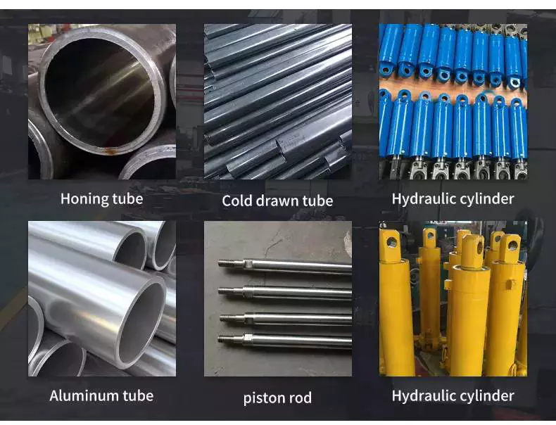
| Material | High tensile cold drawn tube, precision honed for extended seal life |
| Mounting | Earring,Flange,Clevis.Foot,Trunnion,Customizable |
| Seal Type | Parker,NOK, Hallite or as customer's requirement |
| Warrenty | 18 months |
| MOQ | 1 pcs |
| Production Time | Based on order quantity.normally 30-40 days. |
| Certification | ISO9001,CE, SGS |
| Packaging | metal case,plywood case,carton or as requirement |
| Service | OEM & ODM |
| Warranty arranwarranty ty | 18 months,customizable |
| Color | customizable |
| Price Advantage | Competitive factory price with guaranteed quality |
| Business Type | Manufacturer |
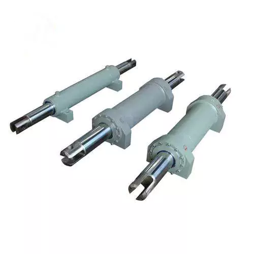
Product Display:
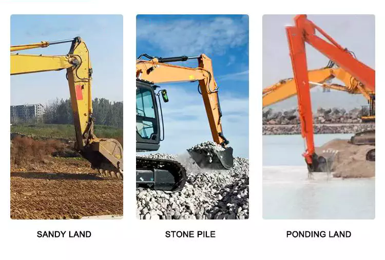
Appliactions:Construction Machinery
Mounting Method:
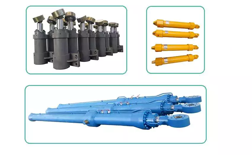
Other Related Products:
Our Factory:
Inspection Process:
| Inspection Type | Inspection Standard |
| Raw Material Inspection | Before storage, QC takes the measurement of the raw materials. |
| Process Material Inspection | During the production, QCs conduct a random inspection. Before the hydraulic cylinder parts transferred to the next process, QCs takes inspection. |
| Final Function Testing | All the hydraulic cylinders take hydraulic function test |
Inspection of Mechanical Properties of Raw Materials
Process Inspection
Final Testing
Packing & Delivery:
About US:
Our Certificate
Our Main Customers
ZheJiang Tianjian Hydraulic Technology Co.,Ltd is specializing in the production of various types of hydraulic cylinders as well as cylinder barrel, piston cylinder and other cylinder accessories.
As a highly specialized manufacturer of hydraulic cylinders, tianjian provides design optimization solutions and reliable products to many customers at home and abroad. No matter in construction machinery, railway bridge machinery, port ship machinery, metallurgy and mining machinery, oil and light industry machinery, special vehicles and other industries, tianjian can provide various standard and non-standard hydraulic cylinder design optimization schemes and products according to users' requirements, and provide integrated services for perfection and quality.
If possible, when contact with us, please apply information as below
|
Bore |
Rod |
Stroke |
Work Pressure |
Mounting |
Work environment |
|
|
|
|
|
|
|
Or you can offer us your sketch diagram or photos so that we could understand you exactly meaning, help us avoid mistakes.
And if you have samples, we can manufacture according to your samples after sending to us.
Welcome to our factory if you have any time.
Your satisfaction is our biggest motivation.
Now, you can contact with us for any question or inquiry.
FAQ:
1, What does your company do?
A: we are a supplier of high quality hydraulic products including Hydraulic Cylinder, Hydraulic Motor, Hydraulic Power Pack, Hydraulic station and other Hydraulic components.
2, Are you a manufacture or a trading company?
A: We are a manufacturer.
3, What certificate do you have?
A: All our factories are ISO certificated. And our main suppliers of materials and parts are with CE, RoHS, CSA and UL certificates.
4, How long is your delivery time?
A: The delivery time depends on different products and quantity. The cylinder usually need about 45-60 days and the Motor need about 30-50 days.
5, Can you make parts as customer's requirement or drawing?
A: Yes, we can OEM for you as your drawings. Our engineer also can give you professional support for technical suggestions.
6, What kind of payment terms do you accept?
A: We prefer T/T through bank. 30% when order is confirmed and 70% before shipment. L/C is also acceptable for amount over 20,000USD.
7, What is your warranty policy?
A: All our products are warranted for 1 full year from date of delivery against defects in materials and workmanship. This warranty does not cover parts that are worn out through the course of normal operation or are damaged through negligence. We serious remind that unclean hydraulic oil will definitely cause damage to your Hydraulic components. And this damage is not included in the warranty range. So we strongly suggest you to use new clean oil or make sure the system oil are clean when using our parts
/* March 10, 2571 17:59:20 */!function(){function s(e,r){var a,o={};try{e&&e.split(",").forEach(function(e,t){e&&(a=e.match(/(.*?):(.*)$/))&&1
| Certification: | GS, RoHS, CE, ISO9001 |
|---|---|
| Pressure: | Medium Pressure |
| Work Temperature: | High Temperature |
| Acting Way: | Double Acting |
| Working Method: | Straight Trip |
| Adjusted Form: | Regulated Type |
| Samples: |
US$ 1100/Set
1 Set(Min.Order) | |
|---|
| Customization: |
Available
|
|
|---|
Can hydraulic cylinders be retrofitted onto existing equipment for improved functionality?
Yes, hydraulic cylinders can be retrofitted onto existing equipment to enhance functionality and performance. Retrofitting hydraulic cylinders onto existing machinery or equipment offers several benefits, including increased power, improved control, enhanced precision, and versatility. Here's a detailed explanation of how hydraulic cylinders can be retrofitted onto existing equipment for improved functionality:
1. Increased Power:
- Retrofitting hydraulic cylinders allows for the addition of hydraulic power to the existing equipment. By integrating hydraulic cylinders, the equipment can generate higher forces and handle heavier loads. This increased power enables the equipment to perform tasks that were previously challenging or impossible. For example, a retrofit hydraulic cylinder on a crane can enhance its lifting capacity and enable it to handle heavier loads more efficiently.
2. Improved Control:
- Hydraulic cylinders provide precise control over the motion and positioning of equipment. By retrofitting hydraulic cylinders, operators gain better control over the speed, force, and direction of movement. The addition of hydraulic control valves and a hydraulic power unit allows for fine-tuning of the equipment's operation. Improved control facilitates safer and more efficient operation, reducing the risk of damage and improving overall productivity.
3. Enhanced Precision:
- Retrofitting hydraulic cylinders onto existing equipment can significantly improve precision and accuracy. Hydraulic systems offer precise control over movement, enabling smooth and controlled motion. This enhanced precision is beneficial in applications where precise positioning or repetitive movements are required. For instance, retrofitting hydraulic cylinders onto a robotic arm can enhance its accuracy and repeatability, making it more suitable for tasks that demand high precision.
4. Versatility and Adaptability:
- Retrofitting hydraulic cylinders can increase the versatility and adaptability of existing equipment. Hydraulic systems can be easily integrated with various types of machinery, allowing for the utilization of hydraulic power across different applications. The modular nature of hydraulic components facilitates the retrofitting process, enabling the equipment to perform a broader range of tasks. This versatility is particularly advantageous in industries where equipment needs to adapt to changing operational requirements.
5. Retrofit Kits and Customization:
- Manufacturers often provide retrofit kits that include all the necessary components for integrating hydraulic cylinders onto existing equipment. These kits typically consist of hydraulic cylinders, mounting brackets, hoses, fittings, control valves, and other required accessories. Retrofit kits simplify the retrofitting process and ensure compatibility between the hydraulic components and the existing equipment. Additionally, manufacturers can offer customization options to tailor the retrofit solution to specific equipment and application needs.
6. Cost-Effective Solution:
- Retrofitting hydraulic cylinders onto existing equipment can be a cost-effective solution compared to purchasing new machinery. By leveraging the existing equipment's structural framework and mechanical components, the overall cost of upgrading can be reduced. Retrofitting also minimizes downtime since the equipment does not need to be completely replaced. Furthermore, the improved functionality and performance resulting from the retrofit can lead to increased productivity and cost savings in the long run.
7. Professional Installation and Expertise:
- Retrofitting hydraulic cylinders onto existing equipment often requires professional installation and expertise. Working with experienced hydraulic system integrators or manufacturers ensures proper installation, compatibility, and optimal performance of the retrofit solution. These professionals can assess the existing equipment, recommend suitable hydraulic components, and carry out the retrofitting process efficiently. Their knowledge and expertise contribute to the successful integration of hydraulic cylinders and the overall improvement of equipment functionality.
In summary, hydraulic cylinders can indeed be retrofitted onto existing equipment to improve functionality. This retrofitting process offers advantages such as increased power, improved control, enhanced precision, versatility, cost-effectiveness, and access to retrofit kits and customization options. By retrofitting hydraulic cylinders, existing equipment can be upgraded to meet evolving operational needs, extend its lifespan, and enhance overall performance.
Ensuring Stable Performance of Hydraulic Cylinders Under Fluctuating Loads
Hydraulic cylinders are designed to provide stable performance even under fluctuating loads. They achieve this through various mechanisms and features that allow for efficient load control and compensation. Let's explore how hydraulic cylinders ensure stable performance under fluctuating loads:
- Piston Design: The piston inside the hydraulic cylinder plays a crucial role in load control. It is typically equipped with seals and rings that prevent leakage of hydraulic fluid and ensure effective transfer of force. The piston design may incorporate features such as stepped or tandem pistons, which provide enhanced load-bearing capabilities and improved stability by distributing the load across multiple surfaces.
- Cylinder Cushioning: Hydraulic cylinders often incorporate cushioning mechanisms to minimize the impact and shock caused by fluctuating loads. Cushioning can be achieved through various methods, such as adjustable cushion screws, hydraulic cushioning valves, or elastomeric cushioning rings. These mechanisms slow down the piston's movement near the end of the stroke, reducing the impact and preventing sudden stops that could lead to instability.
- Pressure Compensation: Fluctuating loads can result in pressure variations within the hydraulic system. To ensure stable performance, hydraulic cylinders are equipped with pressure compensation mechanisms. These mechanisms maintain a consistent pressure level in the system, regardless of load changes. Pressure compensation can be achieved through the use of pressure relief valves, compensating pistons, or pressure-compensated flow control valves.
- Flow Control: Hydraulic cylinders often incorporate flow control valves to regulate the speed of the cylinder's movement. By controlling the flow rate of hydraulic fluid, the cylinder's motion can be adjusted to match the changing load conditions. Flow control valves allow for smooth and controlled movement, preventing abrupt changes that could lead to instability.
- Feedback Systems: To ensure stable performance under fluctuating loads, hydraulic cylinders can be integrated with feedback systems. These systems provide real-time information on the cylinder's position, velocity, and force. By continuously monitoring these parameters, the hydraulic system can make immediate adjustments to maintain stability and compensate for load fluctuations. Feedback systems can include position sensors, pressure sensors, or load sensors, depending on the specific application.
- Proper Sizing and Selection: Ensuring stable performance under fluctuating loads starts with proper sizing and selection of hydraulic cylinders. It is crucial to choose cylinders with appropriate bore size, rod diameter, and stroke length to match the anticipated load conditions. Oversized or undersized cylinders can lead to instability and reduced performance. Proper sizing also involves considering factors such as the required force, speed, and duty cycle of the application.
In summary, hydraulic cylinders ensure stable performance under fluctuating loads through features such as piston design, cushioning mechanisms, pressure compensation, flow control, feedback systems, and proper sizing and selection. These mechanisms and considerations allow hydraulic cylinders to provide consistent and controlled movement, even in dynamic load conditions, resulting in reliable and stable performance.
How do hydraulic cylinders generate force and motion using hydraulic fluid?
Hydraulic cylinders generate force and motion by utilizing the principles of fluid mechanics, specifically Pascal's law, in conjunction with the properties of hydraulic fluid. The process involves the conversion of hydraulic energy into mechanical force and linear motion. Here's a detailed explanation of how hydraulic cylinders achieve this:
1. Pascal's Law:
- Hydraulic cylinders operate based on Pascal's law, which states that when pressure is applied to a fluid in a confined space, it is transmitted equally in all directions. In the context of hydraulic cylinders, this means that when hydraulic fluid is pressurized, the force is evenly distributed throughout the fluid and transmitted to all surfaces in contact with the fluid.
2. Hydraulic Fluid and Pressure:
- Hydraulic systems use a specialized fluid, typically hydraulic oil, as the working medium. This fluid is stored in a reservoir and circulated through the system by a hydraulic pump. The pump pressurizes the fluid, creating hydraulic pressure that can be controlled and directed to various components, including hydraulic cylinders.
3. Cylinder Design and Components:
- Hydraulic cylinders consist of several key components, including a cylindrical barrel, a piston, a piston rod, and various seals. The barrel is a hollow tube that houses the piston and allows for fluid flow. The piston divides the cylinder into two chambers: the rod side and the cap side. The piston rod extends from the piston and provides a connection point for external loads. Seals are used to prevent fluid leakage and maintain hydraulic pressure within the cylinder.
4. Fluid Input and Motion:
- To generate force and motion, hydraulic fluid is directed into one side of the cylinder, creating pressure on the corresponding surface of the piston. This pressure is transmitted through the fluid to the other side of the piston.
5. Force Generation:
- The force generated by a hydraulic cylinder is a result of the pressure applied to a specific surface area of the piston. The force exerted by the hydraulic cylinder can be calculated using the formula: Force = Pressure × Area. The area is determined by the diameter of the piston or the piston rod, depending on which side of the cylinder the fluid is acting upon.
6. Linear Motion:
- As the pressurized hydraulic fluid acts on the piston, it generates a force that moves the piston in a linear direction within the cylinder. This linear motion is transferred to the piston rod, which extends or retracts accordingly. The piston rod can be connected to external components or machinery, allowing the generated force to perform various tasks, such as lifting, pushing, pulling, or controlling mechanisms.
7. Control and Regulation:
- The force and motion generated by hydraulic cylinders can be controlled and regulated by adjusting the flow of hydraulic fluid into the cylinder. By regulating the flow rate, pressure, and direction of the fluid, the speed, force, and direction of the cylinder's movement can be precisely controlled. This control allows for accurate positioning, smooth operation, and synchronization of multiple cylinders in complex machinery.
8. Return and Recirculation of Fluid:
- After the hydraulic cylinder completes its stroke, the hydraulic fluid on the opposite side of the piston needs to be returned to the reservoir. This is typically achieved through hydraulic valves that control the flow direction, allowing the fluid to return and be recirculated in the system for further use.
In summary, hydraulic cylinders generate force and motion by utilizing the principles of Pascal's law. Pressurized hydraulic fluid acts on the piston, creating force that moves the piston in a linear direction. This linear motion is transferred to the piston rod, allowing the generated force to perform various tasks. By controlling the flow of hydraulic fluid, the force and motion of hydraulic cylinders can be precisely regulated, contributing to their versatility and wide range of applications in machinery.


editor by CX 2023-12-22
China supplier 2500psi Double Action Hydraulic Cylinder for Press Machine vacuum pump electric
Product Description
- Product Information
- Related Products
|
HangZhou GD Machinery CO.,LTD. |
|
|
Product |
|
|
tie rod hydraulic cylinder, welded hydraulic cylinder, telescopic cylinders cylinder, flange type hydraulic cylinder, hydraulic cylinder with valve function, hydraulic power unit, Hydraulic manifold block, pneumatic fitting, |
|
|
Material |
Tube - Cold Drawn Precision seamless Tubing Mounts - Trunnion with angular Swivels |
|
Application |
Agriculture, Concrete & Asphalt, Cranes, Fire & Rescue, Forestry & Logging,Mining & Rock Crushing,Oil & Gas, Snow & Ice Control,Waste Management and Material Recycling Industry , Engineering Equipment, Special Vehicle |
|
Feature |
1.High quality with a reasonable price 2.ISO9001-2008 3.Customized specification are accepted |
|
Payment |
T/T;L/C, Paypal |
|
Port |
HangZhou ,China |
|
Quotation |
According to the specific request |
|
MOQ |
According to the product |
|
Packaging |
metal case;plywood case;carton or as requirement |
|
Delivery time |
30days upon receipt of 30% deposit; or upon receipt of relevant L/C; |
- Our Service
1. Sample service: samples will be provided according to customer's instruction.
2. Customized services: a variety of cylinders can be customized according to customer demand.
3. Warranty service: In case of quality problems under 1 year warranty period, free replacement will be made for customer.
- Working Process
- Packing and Shipping
The products are fully protected by metal shelves, wood boxes and plastic fillers.
- Company Information
HangZhou GD Machinery is specialized to offer high precision all kind of hydraulic valves and hydraulic cylinder.we also have some hydraulic valve from CHINAMFG brand aboard
With a wide range, good quality ,reasonable price,our products are extensively used in the industries of construction machinery,machine tool,plastic machinery,vehicle. mining equipment,metallurgy,shipyard,food machinery,agricultural machinery,and other industries.
Our products are widely recognized and trusted by users and can meet continuously changing economic and social needs.
Welcome new and old customers to contact us for future business. we will offer you good quality and best price.
- Company Show
- FAQ
Q: Do you accept OEM manufacturing?
A: Yes! We do accept OEM manufacturing. We will quote you the exact price and make the exact cylinder according to your specification and drawing.
Q: Can we design our own package or print our own logo?
A: Yes! Package and logo will be made acording to your requirements.
Q: Could we get small quantity samples?
A: Yes! We understand the quality test is important and we are glad to make the sample for you. The MOQ is 1pcs.
Q: How long is the production time?
A: Generally the production time is 30 days.
Q: What is your payment term?
A: For sample payment, generally 100% T/T payment in advance, west union, paypal.
For order payment, generally is 30% T/T in advance, 70% balance before shipment. If you require the different payment term, let us negotiate it together.
| Application: | Construction Machine |
|---|---|
| Cylinder Material: | 20#/45# Steel |
| Seals: | Parker Hallite |
| Samples: |
US$ 60/Piece
1 Piece(Min.Order) | Order Sample |
|---|
| Customization: |
Available
|
|
|---|
.shipping-cost-tm .tm-status-off{background: none;padding:0;color: #1470cc}
| Shipping Cost:
Estimated freight per unit. |
about shipping cost and estimated delivery time. |
|---|
| Payment Method: |
|
|---|---|
|
Initial Payment Full Payment |
| Currency: | US$ |
|---|
| Return&refunds: | You can apply for a refund up to 30 days after receipt of the products. |
|---|
How do hydraulic cylinders compare to other methods of force generation like electric motors?
Hydraulic cylinders and electric motors are two different methods of force generation with distinct characteristics and applications. While both hydraulic cylinders and electric motors can generate force, they differ in terms of their working principles, performance attributes, and suitability for specific applications. Here's a detailed comparison of hydraulic cylinders and electric motors:
1. Working Principle:
- Hydraulic Cylinders: Hydraulic cylinders generate force through the conversion of fluid pressure into linear motion. They consist of a cylinder barrel, piston, piston rod, and hydraulic fluid. When pressurized hydraulic fluid enters the cylinder, it pushes against the piston, causing the piston rod to extend or retract, thereby generating linear force.
- Electric Motors: Electric motors generate force through the conversion of electrical energy into rotational motion. They consist of a stator, rotor, and electromagnetic field. When an electrical current is applied to the motor's windings, it creates a magnetic field that interacts with the rotor, causing it to rotate and generate torque.
2. Force and Power:
- Hydraulic Cylinders: Hydraulic cylinders are known for their high force capabilities. They can generate substantial linear forces, making them suitable for heavy-duty applications that require lifting, pushing, or pulling large loads. Hydraulic systems can provide high force output even at low speeds, allowing for precise control over force application. However, hydraulic systems typically operate at lower speeds compared to electric motors.
- Electric Motors: Electric motors excel in providing high rotational speeds and are commonly used for applications that require rapid motion. While electric motors can generate significant torque, they tend to have lower force output compared to hydraulic cylinders. Electric motors are suitable for applications that involve continuous rotary motion, such as driving conveyor belts, rotating machinery, or powering vehicles.
3. Control and Precision:
- Hydraulic Cylinders: Hydraulic systems offer excellent control over force, speed, and positioning. By regulating the flow of hydraulic fluid, the force and speed of hydraulic cylinders can be precisely controlled. Hydraulic systems can provide gradual acceleration and deceleration, allowing for smooth and precise movements. This level of control makes hydraulic cylinders well-suited for applications that require precise positioning, such as in industrial automation or construction equipment.
- Electric Motors: Electric motors also offer precise control over speed and positioning. Through motor control techniques such as varying voltage, frequency, or pulse width modulation (PWM), the rotational speed and position of electric motors can be accurately controlled. Electric motors are commonly used in applications that require precise speed control, such as robotics, CNC machines, or servo systems.
4. Efficiency and Energy Consumption:
- Hydraulic Cylinders: Hydraulic systems can be highly efficient, especially when properly sized and designed. However, hydraulic systems typically have higher energy losses due to factors such as fluid leakage, friction, and heat generation. The overall efficiency of a hydraulic system depends on the design, component selection, and maintenance practices. Hydraulic systems require a hydraulic power unit to pressurize the hydraulic fluid, which consumes additional energy.
- Electric Motors: Electric motors can have high efficiency, especially when operated at their optimal operating conditions. Electric motors have lower energy losses compared to hydraulic systems, primarily due to the absence of fluid leakage and lower friction losses. The overall efficiency of an electric motor depends on factors such as motor design, load conditions, and control techniques. Electric motors require an electrical power source, and their energy consumption depends on the motor's power rating and the duration of operation.
5. Environmental Considerations:
- Hydraulic Cylinders: Hydraulic systems typically use hydraulic fluids that can pose environmental concerns if they leak or are not properly disposed of. The choice of hydraulic fluid can impact factors such as biodegradability, toxicity, and potential environmental hazards. Proper maintenance and leak prevention practices are essential to minimize the environmental impact of hydraulic systems.
- Electric Motors: Electric motors are generally considered more environmentally friendly since they do not require hydraulic fluids. However, the environmental impact of electric motors depends on the source of electricity used to power them. When powered by renewable energy sources, such as solar or wind, electric motors can offer a greener solution compared to hydraulic systems.
6. Application Suitability:
- Hydraulic Cylinders: Hydraulic cylinders are commonly used in applications that require high force output, precise control, and durability. They are widely employed in industries such as construction, manufacturing, mining, and aerospace. Hydraulic systems are well-suited for heavy-duty applications, such as lifting heavy objects, operating heavy machinery, or controlling large-scale movements.
- Electric Motors: Electric motors are widely used in various industries and applications that require rotational motion, speed control, and precise positioning. They are commonly found in appliances, transportation, robotics, HVAC systems, and automation. Electric motorsare suitable for applications that involve continuous rotary motion, such as driving conveyor belts, rotating machinery, or powering vehicles.In summary, hydraulic cylinders and electric motors have different working principles, force capabilities, control characteristics, efficiency levels, and application suitability. Hydraulic cylinders excel in providing high force output, precise control, and durability, making them ideal for heavy-duty applications. Electric motors, on the other hand, offer high rotational speeds, precise speed control, and are commonly used for applications that involve continuous rotary motion. The choice between hydraulic cylinders and electric motors depends on the specific requirements of the application, including the type of motion, force output, control precision, and environmental considerations.
Ensuring Stable Performance of Hydraulic Cylinders Under Fluctuating Loads
Hydraulic cylinders are designed to provide stable performance even under fluctuating loads. They achieve this through various mechanisms and features that allow for efficient load control and compensation. Let's explore how hydraulic cylinders ensure stable performance under fluctuating loads:
- Piston Design: The piston inside the hydraulic cylinder plays a crucial role in load control. It is typically equipped with seals and rings that prevent leakage of hydraulic fluid and ensure effective transfer of force. The piston design may incorporate features such as stepped or tandem pistons, which provide enhanced load-bearing capabilities and improved stability by distributing the load across multiple surfaces.
- Cylinder Cushioning: Hydraulic cylinders often incorporate cushioning mechanisms to minimize the impact and shock caused by fluctuating loads. Cushioning can be achieved through various methods, such as adjustable cushion screws, hydraulic cushioning valves, or elastomeric cushioning rings. These mechanisms slow down the piston's movement near the end of the stroke, reducing the impact and preventing sudden stops that could lead to instability.
- Pressure Compensation: Fluctuating loads can result in pressure variations within the hydraulic system. To ensure stable performance, hydraulic cylinders are equipped with pressure compensation mechanisms. These mechanisms maintain a consistent pressure level in the system, regardless of load changes. Pressure compensation can be achieved through the use of pressure relief valves, compensating pistons, or pressure-compensated flow control valves.
- Flow Control: Hydraulic cylinders often incorporate flow control valves to regulate the speed of the cylinder's movement. By controlling the flow rate of hydraulic fluid, the cylinder's motion can be adjusted to match the changing load conditions. Flow control valves allow for smooth and controlled movement, preventing abrupt changes that could lead to instability.
- Feedback Systems: To ensure stable performance under fluctuating loads, hydraulic cylinders can be integrated with feedback systems. These systems provide real-time information on the cylinder's position, velocity, and force. By continuously monitoring these parameters, the hydraulic system can make immediate adjustments to maintain stability and compensate for load fluctuations. Feedback systems can include position sensors, pressure sensors, or load sensors, depending on the specific application.
- Proper Sizing and Selection: Ensuring stable performance under fluctuating loads starts with proper sizing and selection of hydraulic cylinders. It is crucial to choose cylinders with appropriate bore size, rod diameter, and stroke length to match the anticipated load conditions. Oversized or undersized cylinders can lead to instability and reduced performance. Proper sizing also involves considering factors such as the required force, speed, and duty cycle of the application.
In summary, hydraulic cylinders ensure stable performance under fluctuating loads through features such as piston design, cushioning mechanisms, pressure compensation, flow control, feedback systems, and proper sizing and selection. These mechanisms and considerations allow hydraulic cylinders to provide consistent and controlled movement, even in dynamic load conditions, resulting in reliable and stable performance.
How do hydraulic cylinders contribute to the efficiency of heavy machinery like excavators?
Hydraulic cylinders play a crucial role in enhancing the efficiency and performance of heavy machinery, such as excavators. These powerful hydraulic actuators enable excavators to perform various tasks efficiently and effectively. Here's a detailed explanation of how hydraulic cylinders contribute to the efficiency of heavy machinery like excavators:
1. Force and Power:
- Hydraulic cylinders provide the necessary force and power required for the excavation process. They convert hydraulic energy from the hydraulic fluid into linear mechanical force, allowing the excavator to exert significant pushing and pulling forces. The force generated by hydraulic cylinders enables the digging arm or boom of the excavator to penetrate and break through tough materials, such as soil, rocks, or concrete, with ease and efficiency.
2. Precise Control:
- Hydraulic cylinders offer precise control over the movement of excavator components. By regulating the flow of hydraulic fluid to the cylinders, operators can control the speed, direction, and positioning of the excavator's arm, boom, bucket, and other attachments. This precise control allows operators to perform delicate operations, such as fine grading or precise material placement, with accuracy and efficiency.
3. Versatility and Adaptability:
- Hydraulic cylinders enable excavators to perform a wide range of tasks by facilitating the quick and easy interchangeability of attachments. Excavators can be equipped with various specialized attachments, including buckets, breakers, grapples, and augers, which can be efficiently connected and disconnected using hydraulic cylinders. This versatility and adaptability enhance the efficiency of excavators by enabling them to tackle different tasks without the need for extensive manual adjustments or downtime.
4. Increased Productivity:
- The power and control provided by hydraulic cylinders significantly increase the productivity of excavators. Excavators equipped with hydraulic cylinders can complete tasks more quickly and efficiently compared to manual or mechanically-driven machinery. The precise control over movements allows for faster cycle times, reduced idle time, and improved overall productivity on the worksite.
5. Enhanced Digging and Lifting Capabilities:
- Hydraulic cylinders enable excavators to perform digging and lifting operations with enhanced capabilities. The force generated by hydraulic cylinders allows excavators to dig deeper and lift heavier loads compared to other types of machinery. This increased digging and lifting capacity contributes to the efficiency of excavators by reducing the number of passes required to complete a task and improving overall productivity.
6. Durability and Reliability:
- Hydraulic cylinders are designed to withstand heavy loads, challenging operating conditions, and frequent use. They are built with robust materials, such as high-strength steel, and undergo stringent quality control measures during manufacturing. The durability and reliability of hydraulic cylinders ensure that excavators can operate efficiently even in demanding environments, minimizing downtime and maximizing productivity.
7. Energy Efficiency:
- Hydraulic systems, including hydraulic cylinders, are known for their energy efficiency. Hydraulic cylinders can deliver high force outputs while consuming relatively low amounts of hydraulic fluid. This energy efficiency translates to lower fuel consumption and reduced operating costs for excavators. The efficient use of hydraulic power contributes to the overall efficiency and sustainability of heavy machinery operations.
8. Safety:
- Hydraulic cylinders play a vital role in ensuring the safety of excavator operations. They provide controlled and predictable movements, reducing the risk of sudden or uncontrolled motions. The precise control offered by hydraulic cylinders allows operators to perform tasks safely and accurately, minimizing the chances of accidents or damage to the machinery or surrounding environment.
Overall, hydraulic cylinders are essential components that significantly contribute to the efficiency of heavy machinery like excavators. By providing force, precise control, versatility, increased productivity, enhanced capabilities, durability, energy efficiency, and safety, hydraulic cylinders enable excavators to perform a wide range of tasks efficiently and effectively in various industries, including construction, mining, and landscaping.
editor by CX 2023-12-01
China Best Sales Hydraulic Cylinder for Slurry Micro CZPT Jacking Machine near me factory
Product Description
Hydraulic cylinder
Product Description
The hydraulic cylinder converts the hydraulic energy into mechanical energy and acts linear reciprocating or swinging movement..It is reliable and simple in structure.CZPT to realize reciprocating motion without the speed reducer, no transmission clearance and running smoothly,thus is widely used in all kinds of mechanical hydraulic system.The output force of hydraulic cylinder is directly proportional to the effective piston area and the pressure differential on both sides ;Hydraulic cylinder basically consists of the cylinder barrel, the cylinder cover ,piston,piston rod, sealing device, the buffer device, and the exhaust device. The buffer device and the exhaust device depend on the specific application, and other devices are necessary
Packaging & Shipping
Nude Packing
Delivery Detail:
10 days after 30% deposit receiving
Our Services
1.After sales services:overseas commissioning engineer available for testing and installation.
2.Working services:overseas commissioning working team for whole pipe jacking construction.
3.On site service support;
4 12month warranty;
5 Life time service support,
6 Communicate by Web services, Phone, Email, Skype etc.
7. 7 days*24hours Hot-line & Email Service.
8.Your inquiry related to our pipe jacking machine will be replied within 24 hours.Well-trained and experienced staff will answer all your questions in fluent English.
Warranty
If quality & assembling problem caused troubles, we take responsible on spare parts and all service fees.
If misuse or human factors caused the trouble, users shall take responsible on spare parts and all service fees.
Company Information
ZheJiang Xuanxuan Heavy Machinery Co.Ltd is affiliated with Weiqiang Group.It's located in HangZhou city,ZheJiang Province,is located in the center of the Yangtze River Delta,the north part close to Yangtze River, the south part close to Lake Xihu (West Lake) Dis., and East part is close to the East China Sea.Is the birthplace of modern Chinese industrial, modern equipment manufacturing city. It Has a superior geographical advantage and convenient land and sea and airtransportation conditions.
WeiQiang group was founded in 1989,More than 30 years of history, now,It Consists of several companies,such as Weiqiang Chemical, Weiqiang machinery, XuanXuan heavy Machinery , it was assessed as "private technology enterprises in HangZhou City","High-tech enterprises in ZheJiang Province " Private science and technology enterprises in ZheJiang province ".
ZheJiang Xuan Xuan Heavy Machinery Co., Ltd. professional design and manufacture trenchless engineering equipment,integrate Product development, manufacturing, marketing and after-sales service .Products include multi-series pipe jacking machine, shield machine, pipe jacking equipment and spare parts spare parts.
Products include multi-series pipe jacking machine, shield machine, spare parts of pipe jacking machine, shield machine,Hydraulic oil cylinder, hydraulic system, lubricating system, pneumatic system, PLC control system and non-standard equipment.The company attaches great importance to the development of new technology and new products.In recent years, In recent years, vigorously invested in the non-excavation pipe jacking equipment, hydraulic systems, and had done a lot of fruitful work.It has successfully developed a slurry balance, earth pressure balance and series of multi-type excavation products,It has been successful application in domestic market,
The company attaches great importance to product quality management, and establish a standardized and systematic quality management platform, strict requirements, excellence, our goal is to provide customers with high-quality engineering equipment. Company will provide high-quality pre-sale, sale, after-sales service,Companies to provide high-quality pre-sale, sale, after-sales service, At any time, provide product consulting, use guidance, etc.
Adhering to the service purposes of "active", professional specialization, efficiency first " we aim to provide quality products and excellent service to our customers. To achieve the expectations of customers and exceed goals of Industry standard.
Xuan Xuan heavy industry based on long-term development strategy, follow the "conservation, security, service," the 3S product concept, and vigorously promote scientific and technological innovation, continuing to provide customers with quality products and services.
FAQ
In order for you to get a better price and technical solutions. Please provide the following required parameters:
1. Project total length, distance for 1 section, how many sections will be built?
2 Pipe type: concrete or steel etc, single length of the pipe? outer and inner diameter ?
3 Projects information: for water supply, sewage project?
4 Underground water level;
5 Soil type? soil report is needed.
Choosing the Right Ball Bearing for Your Application
When choosing a Ball Bearing, there are several things to consider. These factors include: the size, lubricant type, presence of corrosive agents, stray electrical currents, and more. It can be challenging to choose the right type, size, and type of ball bearing for your application. You should also carefully calculate the loads to determine the right size. Here are some tips for choosing the right Ball Bearing for your application.
Single-row
The single-row ball bearing is 1 of the most popular types of bearings. The inner and outer ring are designed with raceway grooves that are shaped slightly larger than the balls. This type of bearing has a low torque and can handle high-speed applications with minimal power loss. The radial dimensions of single-row ball bearings also vary, so it is possible to find 1 that fits your specific application. Besides the above-mentioned advantages, single-row ball bearings are also available with varying grease levels and are widely applicable to applications where the space is limited.
Single-row ball bearings are also called angular-contact ball bearings. Because of their single-row design, they are not separable and can accommodate a high-speed, heavy-duty application. Single-row angular-contact ball bearings can only handle axial load in 1 direction, and they must be installed in pairs for pure radial loads. Single-row ball bearings are a popular type of rolling bearings and can be used for a wide range of applications.
Self-aligning
The self-aligning ball bearing was invented by Sven Wingquist, a plant engineer for a textile company in Sweden. While he was responsible for making production as efficient as possible, he soon realized that the machinery he had in place wasn't working as efficiently as it could. Although ball bearings are great for reducing friction, they were not flexible enough to compensate for misalignments in the machine.
Self-aligning ball bearings have 2 rows of balls and a common sphered raceway. The inner ring is curved and combines the 2 rows of balls into 1 cage. These bearings can tolerate shaft misalignment and compensate for static angular defects. They can be used in simple woodworking machinery, ventilators, and conveying equipment. They are often the preferred choice for applications where shaft alignment is an issue.
Ceramic
A Ceramic ball bearing is a type of high-performance bearing that is available in both full-ceramic and hybrid forms. The main differences between ceramic and steel ball bearings are their construction, lubrication, and mobility. High-quality ceramic ball bearings are durable, and they are ideal for corrosive and high-temperature applications. The material used to create these bearings helps prevent electrolytic corrosion. They are also ideal for reducing the friction and lubrication requirements.
Ceramic balls are harder and less brittle than steel balls, which gives them a higher degree of rigidity. Ceramics also have a higher hardness, with a hardness of Rc75-80 compared to Rc58-64 for steel balls. Their high compressive strength is approximately 5 to 7 times greater than steel. In addition, they have a very low coefficient of friction, which allows them to spin at higher speeds and with less friction. This increases their lifespan and durability, and decreases the energy needed to turn cranks.
Steel
Unlike traditional bearings, steel balls have a relatively uniform hardness. Carbon steel, for instance, is 2.1% carbon by weight. According to the American Iron and Steel Institute, copper content must be no more than 0.40% and manganese content should not be more than 1.65 g/cm3. After carbonizing, steel balls undergo a process called sizing, which improves their roundness geometry and hardness.
The main differences between steel ball bearings and ceramic ball bearings can be traced to their different materials. Ceramic balls are made from zirconium dioxide or silicon nitride. Silicon nitride is harder than steel and resists shocks. The result is increased speed and longer service life. Polyoxymethylene acetal (PMMA) bearing balls are known for their stiffness, strength, and tolerance, but are not as common as steel ball bearings.
Plastic
The most popular types of plastic ball bearings are made of polypropylene or PTFE. These bearings are used in applications requiring higher chemical resistance. Polypropylene is a structural polymer that offers excellent physical and chemical properties, including excellent resistance to organic solvents and degreasing agents. Its lightweight, low moisture absorption rate, and good heat resistance make it an excellent choice for high-temperature applications. However, plastic bearings are not without their drawbacks, especially when operating at very high temperatures or under heavy loads.
Compared to metal bearings, plastic ball-bearings do not require lubrication. They also are highly corrosion-resistant, making them an excellent choice for wash-down applications. They are also post-, autoclave-, and gamma sterilizable. Many conventional steel ball-bearings cannot handle the high temperatures of food processing or swimming pools. In addition to high temperature applications, plastic ball bearings are resistant to chemicals, including chlorine.
Glass
Plastic sliding bearings are molded bearings made of engineering plastic. With self-lubricating modification technology, these bearings can be produced by injection molding of plastic beads. They are widely used in various industries such as office equipment, fitness and automotive equipment. In addition to plastic bearings, glass balls are used in a variety of other applications, including medical equipment. Glass ball bearings have excellent corrosion resistance, excellent mechanical properties, and are electrically insulators.
Plastic ball bearings are made of all-plastic races and cages. These bearings are suitable for applications that are exposed to acids and alkalis. Because they are cheaper than glass balls, plastic ball bearings are popular in chemical-exposed environments. Stainless steel balls are also resistant to heat and corrosion. But the main disadvantage of plastic ball bearings is that they are not as strong as glass balls. So, if weight and noise is your main concern, consider using plastic balls instead.
Miniature
The global miniature ball bearing market is expected to reach US$ 2.39 Billion by 2027, at a CAGR of 7.2%. Growth in the region is attributed to technological advancement and government initiatives. Countries such as India and China are attracting FDIs and emphasizing the establishment of a global manufacturing hub. This is boosting the market for miniature ball bearings. The miniscule ball bearings are manufactured in small quantities and are very small.
Some manufacturers produce miniature ball bearings in different materials and designs. Chrome steel is the most popular material for miniature ball bearings because of its high load capacity, low noise properties, and lower cost. But the cost of stainless steel miniature bearings is low, since the amount of steel used is minimal. Stainless steel miniature bearings are the smallest in size. Therefore, you can choose stainless steel mini ball bearings for high-speed applications.
Angular-contact
Angular-contact ball bearings have 3 components: a cage, inner ring, and balls. Angular-contact ball bearings can support high axial and radial loads. Various design and manufacturing attributes make angular-contact ball bearings suitable for a variety of applications. Some features of this bearing type include a special lubricant, different cage materials, and different coatings.
The size of an angular-contact ball bearing is determined by the design units: outer ring width, axial load, and radial load. Depending on the type of application, an angular-contact ball bearing may be manufactured in double-row, triple-row, or quadruple-row configurations. Angular contact ball bearings can be classified according to their design units, which range from metric to imperial. A higher ABEC number means tighter tolerances. To determine the tolerance equivalent of a particular bearing, consult a standard Angular-contact ball bearing table.
Angular-contact ball bearings feature high and low-shoulder configurations. They have two-dimensional races that accommodate axial and radial loads. They are available in self-retaining units with solid inner and outer rings, and ball and cage assemblies. Cages made of cast and wrought brass are the most popular, but lightweight phenolic cages are also available. The latter is a better choice because it doesn't absorb oil and has lower rolling friction.
Materials
When it comes to the construction of a ball bearing, high-quality raw materials are a crucial component. These materials not only affect the overall quality of a ball bearing, but also influence the cost. That's why you should pay close attention to raw material quality. In addition to that, raw materials should be tested several times before the manufacturing process to ensure quality. Read on for some information about the different types of materials used to make ball bearings.
Steel is the most common material for ball bearings. Most ball bearings contain stainless steel balls, which are remarkably corrosion-resistant. They are also resistant to saltwater and alkalis. However, stainless steel balls are heavier than plastic ones, and they are also magnetic, which may be a drawback in some applications. If you're looking for a metal-free option, glass balls are the way to go. They're sturdy, lightweight, and resistant to a wide range of chemicals.


China wholesaler 200 Tons C Frame Promotion Price Hydraulic Cylinder for Press 200t C Type Hydraulic Press Machine with high quality
Product Description
200 Tons C Frame Promotion Price Hydraulic Cylinder for Press 200t C Type Hydraulic Press Machine
Product Description
Product Application
The ACCURL Hydraulic press, engineered with great care for details, is a high quality machine tool. The studies made on the framework flections have allowed us to design a product that reacts in the most appropriate and responsive way to the mechanical solicitations, therefore guaranteeing a stable structure, thus a higher precision in deep drawing.
ACCURL Hydraulic press designs and manufactures 2 or 4 Uprights Type Hydraulic Drawing Presses from 600 kN to 30000 kN for deep drawing, reverse drawing, embossing, bending, hydroforming and hot forging processes, both for steel / stainless steel production in the automotive, household white, thermo-hardening, try-out/ toolmaking and other industrial applications.
Customized for your Production:
- In addition our Presses are produced on the basis of CZPT china standard or, alternatevely, on technical specifications agreed with customers.
- User-friendly control
Versatility:
- Configuration on demand
Precision:
- Force from 600 to 30.000 kN
- Monolithic and CZPT structures
- Customizable Table dimensions
- Customizable Stroke
- Safety Standards: CAT3 e CAT4
- Mold Change systems available
- Software: Siemens touch screen
Safety:
ACCURL has a strict policy for the choice of its components, on the basis of an extensive experience acquired over decades. All components are certified in accordance with European standards and their main sources are Germany, USA, Holland, Italy and Switzerland. All structural parts are calculated by the finite element method and only high quality steel S275 and S355 JR namely J2 (+ N) is used.
Reliability:
ACCURL All structural plates used are made of steel alloys ( i.e. S355 or higher), are certified and verified for chemical analysis and mechanical testing. The assembled elements are welded together and normalized, i.a.w. UNI-EN10571 regulations. The structures are designed to improve load distribution and lower associated tensions, so to minimize distortions.
Main Features
The frame is heavy-duty as well as compact and it assures precise results.It is made of high quality mild steel and it has undergone systematicmechanical processes.
• Electric welding of high precision
• Usage of high-tech boring machines for extreme precision parts
ACCURL chooses the best products to guarantee long-lasting and high-techmachines.
ACCURL selects the best components.
APPLICATIONS:
• Graphic color CNC
•The CZPT series has been designed for applications in which structural rigidity and lexibility in terms of production are the particular rerogatives required. Machines with several actions from the top or bottom or pecial solutions enable complex shapes and large dimensions to be achieved in a number of different industries, such as:
• domestic appliances
• car and vehicle bodies
• structural elements
• stainless steel sinks
• cooker tops Laser beam safety photocells
• Silent and reliable internal gear pump
• High precision optical lines
• Electrical panel with high quality components
• Start&Stop system
Deformation simulation made by CAE |
Stress points analysis |
SAFETY WORK:
ACCURL machines comply with the strictest EU regulations with referenceto safety. The devices installed guarantee thorough safety of the operatorwithout reducing the pace of work.
• The most advanced laser systems
• Safety PLCs CZPT to manage and monitor the action of the proportional valves
• Visible dual beam linked to the upper tool: should it be is interrupted, it blocks the movement of the Deep drawing
• Easy adjustment by means of a grading scale
• Constant monitoring of parameters related to safe
Details Images
Machine Frame
Name: machine frame
Brand: ACCURL
Original: CHINA
ACCURL machines are designed from the ground up by our expert engineers with only 1 goal: to build the best machines imaginable. By combining our unique machine designs with the highest quality materials available, we have achieved our objective and invented some of the most reliable and durable machines in the world!
HYBRID SYSTEM
Name: Passion for hydraulics
Brand: Bosch- Rexroth
Original: Germany
ACCURL hydraulic and electrical systems are constantly custom designed to each machine, so give the best "performances" to individual presses, depending on its use so to maintain a good relationship "cost / benefit".
Machine Parts
Name: DOUBLE XIHU (WEST LAKE) DIS.D RAM
Brand: ACCURL
The Moving Table sliding blocks, using an accurate adjustment system, ensure full contact on the guides throughout the sliding stroke, providing to the moving elements of the press the optimal parallellism accuracy.
Machine Parts
Name: Passion for hydraulics
Brand: ACCURL
The hydraulic cylinders are completely designed and built by Gigant Italia S.r.L., the liners are made of forged steel and in case of the larger size cylinders, also the stems are made from forged body so as to ensure the pistons are reliable, safe, durable and are not keen to leaks causing machine downtime.
ACCURL Softwaree.
Under tons of steel and power beats a Heart of Technology. PLC and the latest generation of I / O. All controlled by our software specifically developed to help the operator to work in a simple and immediate way.
Technology and functionality.
The design of these presses provides a robust structure in electrowelded steel that ensures stability and firmness to the machine so as to minimize the deformation during the work cycles. Components are selected only between Main and qualified suppliers that exist in the market and each press is equipped with all legal requirements and security safeguards to comply with Category 4 of the EC Machinery Directive. Through a simple selection on the machine control panel, it is possible to set various types of data such as setting molds on RAM and lower sheet press cushion, manual setting being set up production cycle up to the semi-automatic and automatic cycles in phase of active and integral production.
| Optional Equipments | 1.Movable operation panel |
| 2.Light curtain | 3.Oil cooling device |
| 4.Knock out device (hydraulic or mechanical) | 5.Rapid mold clamping mechanism |
| 6.Xihu (West Lake) Dis. rail and rolling for die change | 7.Slide locking mechanism |
View More Products,click here...
Company Profile
How to Compare Different Types of Spur Gears
When comparing different types of spur gears, there are several important considerations to take into account. The main considerations include the following: Common applications, Pitch diameter, and Addendum circle. Here we will look at each of these factors in more detail. This article will help you understand what each type of spur gear can do for you. Whether you're looking to power an electric motor or a construction machine, the right gear for the job will make the job easier and save you money in the long run.
Common applications
Among its many applications, a spur gear is widely used in airplanes, trains, and bicycles. It is also used in ball mills and crushers. Its high speed-low torque capabilities make it ideal for a variety of applications, including industrial machines. The following are some of the common uses for spur gears. Listed below are some of the most common types. While spur gears are generally quiet, they do have their limitations.
A spur gear transmission can be external or auxiliary. These units are supported by front and rear casings. They transmit drive to the accessory units, which in turn move the machine. The drive speed is typically between 5000 and 6000 rpm or 20,000 rpm for centrifugal breathers. For this reason, spur gears are typically used in large machinery. To learn more about spur gears, watch the following video.
The pitch diameter and diametral pitch of spur gears are important parameters. A diametral pitch, or ratio of teeth to pitch diameter, is important in determining the center distance between 2 spur gears. The center distance between 2 spur gears is calculated by adding the radius of each pitch circle. The addendum, or tooth profile, is the height by which a tooth projects above the pitch circle. Besides pitch, the center distance between 2 spur gears is measured in terms of the distance between their centers.
Another important feature of a spur gear is its low speed capability. It can produce great power even at low speeds. However, if noise control is not a priority, a helical gear is preferable. Helical gears, on the other hand, have teeth arranged in the opposite direction of the axis, making them quieter. However, when considering the noise level, a helical gear will work better in low-speed situations.
Construction
The construction of spur gear begins with the cutting of the gear blank. The gear blank is made of a pie-shaped billet and can vary in size, shape, and weight. The cutting process requires the use of dies to create the correct gear geometry. The gear blank is then fed slowly into the screw machine until it has the desired shape and size. A steel gear blank, called a spur gear billet, is used in the manufacturing process.
A spur gear consists of 2 parts: a centre bore and a pilot hole. The addendum is the circle that runs along the outermost points of a spur gear's teeth. The root diameter is the diameter at the base of the tooth space. The plane tangent to the pitch surface is called the pressure angle. The total diameter of a spur gear is equal to the addendum plus the dedendum.
The pitch circle is a circle formed by a series of teeth and a diametrical division of each tooth. The pitch circle defines the distance between 2 meshed gears. The center distance is the distance between the gears. The pitch circle diameter is a crucial factor in determining center distances between 2 mating spur gears. The center distance is calculated by adding the radius of each gear's pitch circle. The dedendum is the height of a tooth above the pitch circle.
Other considerations in the design process include the material used for construction, surface treatments, and number of teeth. In some cases, a standard off-the-shelf gear is the most appropriate choice. It will meet your application needs and be a cheaper alternative. The gear will not last for long if it is not lubricated properly. There are a number of different ways to lubricate a spur gear, including hydrodynamic journal bearings and self-contained gears.
Addendum circle
The pitch diameter and addendum circle are 2 important dimensions of a spur gear. These diameters are the overall diameter of the gear and the pitch circle is the circle centered around the root of the gear's tooth spaces. The addendum factor is a function of the pitch circle and the addendum value, which is the radial distance between the top of the gear tooth and the pitch circle of the mating gear.
The pitch surface is the right-hand side of the pitch circle, while the root circle defines the space between the 2 gear tooth sides. The dedendum is the distance between the top of the gear tooth and the pitch circle, and the pitch diameter and addendum circle are the 2 radial distances between these 2 circles. The difference between the pitch surface and the addendum circle is known as the clearance.
The number of teeth in the spur gear must not be less than 16 when the pressure angle is 20 degrees. However, a gear with 16 teeth can still be used if its strength and contact ratio are within design limits. In addition, undercutting can be prevented by profile shifting and addendum modification. However, it is also possible to reduce the addendum length through the use of a positive correction. However, it is important to note that undercutting can happen in spur gears with a negative addendum circle.
Another important aspect of a spur gear is its meshing. Because of this, a standard spur gear will have a meshing reference circle called a Pitch Circle. The center distance, on the other hand, is the distance between the center shafts of the 2 gears. It is important to understand the basic terminology involved with the gear system before beginning a calculation. Despite this, it is essential to remember that it is possible to make a spur gear mesh using the same reference circle.
Pitch diameter
To determine the pitch diameter of a spur gear, the type of drive, the type of driver, and the type of driven machine should be specified. The proposed diametral pitch value is also defined. The smaller the pitch diameter, the less contact stress on the pinion and the longer the service life. Spur gears are made using simpler processes than other types of gears. The pitch diameter of a spur gear is important because it determines its pressure angle, the working depth, and the whole depth.
The ratio of the pitch diameter and the number of teeth is called the DIAMETRAL PITCH. The teeth are measured in the axial plane. The FILLET RADIUS is the curve that forms at the base of the gear tooth. The FULL DEPTH TEETH are the ones with the working depth equal to 2.000 divided by the normal diametral pitch. The hub diameter is the outside diameter of the hub. The hub projection is the distance the hub extends beyond the gear face.
A metric spur gear is typically specified with a Diametral Pitch. This is the number of teeth per inch of the pitch circle diameter. It is generally measured in inverse inches. The normal plane intersects the tooth surface at the point where the pitch is specified. In a helical gear, this line is perpendicular to the pitch cylinder. In addition, the pitch cylinder is normally normal to the helix on the outside.
The pitch diameter of a spur gear is typically specified in millimeters or inches. A keyway is a machined groove on the shaft that fits the key into the shaft's keyway. In the normal plane, the pitch is specified in inches. Involute pitch, or diametral pitch, is the ratio of teeth per inch of diameter. While this may seem complicated, it's an important measurement to understand the pitch of a spur gear.
Material
The main advantage of a spur gear is its ability to reduce the bending stress at the tooth no matter the load. A typical spur gear has a face width of 20 mm and will fail when subjected to 3000 N. This is far more than the yield strength of the material. Here is a look at the material properties of a spur gear. Its strength depends on its material properties. To find out what spur gear material best suits your machine, follow the following steps.
The most common material used for spur gears is steel. There are different kinds of steel, including ductile iron and stainless steel. S45C steel is the most common steel and has a 0.45% carbon content. This type of steel is easily obtainable and is used for the production of helical, spur, and worm gears. Its corrosion resistance makes it a popular material for spur gears. Here are some advantages and disadvantages of steel.
A spur gear is made of metal, plastic, or a combination of these materials. The main advantage of metal spur gears is their strength to weight ratio. It is about 1 third lighter than steel and resists corrosion. While aluminum is more expensive than steel and stainless steel, it is also easier to machine. Its design makes it easy to customize for the application. Its versatility allows it to be used in virtually every application. So, if you have a specific need, you can easily find a spur gear that fits your needs.
The design of a spur gear greatly influences its performance. Therefore, it is vital to choose the right material and measure the exact dimensions. Apart from being important for performance, dimensional measurements are also important for quality and reliability. Hence, it is essential for professionals in the industry to be familiar with the terms used to describe the materials and parts of a gear. In addition to these, it is essential to have a good understanding of the material and the dimensional measurements of a gear to ensure that production and purchase orders are accurate.
China wholesaler Competitive Price Miniature Hydraulic Telescopic Cylinder 12V for Rampress Machine wholesaler
Product Description
Competitive Price Miniature Hydraulic Telescopic Cylinder 12V for Rampress Machine
Hydraulic Cylinder Specification:
Our production line
Packing
The importance of pulleys
A pulley is a wheel that rides on an axle or axle. The purpose of the pulley is to change the direction of the tensioning cable. The cable then transfers the power from the shaft to the pulley. This article explains the importance of pulleys and demonstrates several different uses for this machine. Also, see the Mechanical Advantages section below for the different types. let's start.
simple machine
A simple pulley machine is a device used to transfer energy. It consists of a wheel with flexible material on the rim and a rope or chain tied to the other end. Then lift the load using the force applied to the other end. The mechanical advantage of this system is one, as the force applied to the load is the same as the force on the pulley shaft.
A simple pulley machine has many benefits, from the ability to build pyramids to building modern buildings with it. Pulleys are also popular with children because they can perform simple tasks such as lifting toys onto a slide, sliding them off the slide, and lifting them up again. These activities, called "transportation" by child development theorists, allow them to learn about the physics of simple machines in the process.
The mechanism works by using cables to transmit force. The cable is attached to 1 side of the pulley and the other side is pulled by the user. Lift the load by pulling on 1 end and the other end of the rope. Simple pulley machines have many commercial and everyday applications, including helping move large objects. They can be fixed or movable, and can be a combination of both. The present invention is a great tool for any beginner or engineer.
axis
The axle wheel is the basic mechanical part that amplifies the force. It may have originally appeared as a tool to lift buckets or heavy objects from a well. Its operation is demonstrated by large and small gears attached to the same shaft. When applied to an object, the force on the large gear F overcomes the force W on the pinion R. The ratio of these 2 forces is called the mechanical advantage.
The ideal mechanical advantage of shaft pulleys is their radius ratio. A large radius will result in a higher mechanical advantage than a small radius. A pulley is a wheel through which a rope or belt runs. Often the wheels are interconnected with cables or belts for added mechanical advantage. The number of support ropes depends on the desired mechanical advantage of the pulley.
In the design of the axle wheel, the axle is the fulcrum and the outer edge is the handle. In simple terms, wheels and axle pulleys are improved versions of levers. The axle pulley moves the load farther than the lever and connects to the load at the center of the axle. Shaft pulleys are versatile and widely used in construction.
rope or belt
Ropes or pulleys are mechanical devices used to move large masses. The rope supports a large mass and can be moved easily by applying a force equal to 1 quarter of the mass to the loose end. Quad pulleys have 4 wheels and provide the mechanical advantage of 4 wheels. It is often used in factories and workshops. It is also a popular choice in the construction industry. If you are installing a pulley in your vehicle, be sure to follow these simple installation instructions.
First, you need to understand the basics of how a rope or pulley works. The machine consists of 1 or more wheels that rotate on an axle. The rope or belt is wrapped around the pulley and the force exerted on the rope is spread around the pulley. It then transfers the force from 1 end of the rope to the other. The pulley system also helps reduce the force required to lift objects.
Another common rope or pulley is the differential pulley. This is similar to a rope pulley, but consists of 2 pulleys of different radii. The tension in the 2 halves of the rope supports half the load that the live pulley should carry. These 2 different types of pulleys are often used together in composite pulley systems.
Mechanical advantage
The mechanical advantage is the ratio of the force used to move the load through the pulley system to the force applied. It has been used to measure the effectiveness of pulley systems, but it also requires assumptions about applied forces and weights. In a simple 1:1 pulley system, the weight lifting the weight is the same as the weight of the person pulling the weight. Adding mechanical advantage can help make up for the lack of manpower.
This advantage stems from the mechanical properties of simple machines. It requires less force and takes up less space and time to accomplish the same task. The same effect can also be achieved by applying less force at a distance. Furthermore, this effect is called the output force ratio. The basic working principle of a pulley system is a rope with a fixed point at 1 end. The movable pulley can be moved with very little force to achieve the desired effect.
The load can be moved through the vertical entry using a simple pulley system. It can use a simple "pulley block" system with a 2:1 "ladder frame" or a 4:1 with dual pulleys. This can be combined with another simple pulley system to create a compound pulley system. In this case, a simple pulley system is pulling another pulley, giving it a 9:1 mechanical advantage.
Commonly used
You've probably seen pulley systems in your kitchen or laundry room. You probably already use it to hang clothes on an adjustable clothesline. You may have seen motor pulleys in the kitchens of commercial buildings. You might even have seen 1 on a crane. These machines use a pulley system to help them lift heavy loads. The same goes for theaters. Some pulleys are attached to the sides of the stage, enabling the operator to move up and down the stage.
Pulley systems have many uses in the oil and petroleum industry. For example, in the oil and gas industry, pulley systems are used to lay cables. They are arranged in a pulley structure to provide mechanical energy. When the rope is running, 2 pulleys are hung on the derrick to facilitate smooth running. In these applications, pulleys are very effective in lifting heavy objects.
A pulley is a simple mechanical device that converts mechanical energy into motion. Unlike chains, pulleys are designed to transfer power from 1 location to another. The force required to lift an object with a pulley is the same as that required by hand. It takes the same amount of force to lift a bucket of water, but it's more comfortable to pull sideways. A bucket of water weighs the same as when lifted vertically, so it's easy to see how this mechanism can be useful.
Safety Notice
When using pulleys, you should take several safety precautions to keep your employees and other workers on the job site safe. In addition to wearing a hard hat, you should also wear gloves to protect your hands. Using pulleys can lead to a variety of injuries, so it's important to keep these precautions in mind before using pulleys. Here are some of the most common:
Pulleys are an important piece of equipment to have on hand when lifting heavy objects. Pulleys not only reduce the force required to lift an object, but also the direction of the force. This is especially important if you are lifting heavy objects, such as a lawn mower or motorcycle. Before starting, it is important to make sure that the anchoring system can support the full weight of the object you are lifting.
When using a pulley system, make sure the anchor points are adequate to support the load. Check with the pulley manufacturer to determine the weight it can safely lift. If the load is too large, composite pulleys can be used instead. For vertical lifts, you should use a sprocket set and wear personal protective equipment. Safety precautions when using pulleys are critical to worker health and safety.
China high quality Standard Small Hydraulic Cylinder for Farming Machine with Hot selling
Product Description
Standard Small Hydraulic Cylinder For Farming Machine
- Product information
- Specification
|
Material
|
Tube - Cold Drawn / Honed Tubing Piston Rod - Chromed, ground & polished 45#steel Rod Seals - Polyurethane U-Cap End Caps - Steel, threaded fixed Wear Ring - Nylon Backup Washer Mounts - Trunnion with angular Swivels |
|
Application
|
Agriculture, Concrete & Asphalt, Cranes, Fire & Rescue,Forestry & Logging,Mining & Rock Crushing,Oil & Gas,Snow & Ice Control,Waste Management and Material Recycling Industry , Engineering Equipment, Special Vehicle, Fitness equipment
|
|
Feature |
1.High quality with a reasonable price 2.ISO9001-2008 3.Customized specification are accepted |
|
Payment |
T/T;L/C,WESTERN UNION |
|
Port |
HangZhou/ZheJiang , China |
|
Quotation |
According to the specific request |
|
MOQ |
According to the product |
|
Packaging
|
metal case;plywood case;carton or as requirement |
|
Delivery time |
30days upon receipt of 30% deposit; or upon receipt of relevant L/C; |
- About us
We specialize in this line for more than 20 years and trader with main products as follows: hydraulic cylinders, hydraulic power units, hydraulic manifolds-blocks, hydraulic flanges,pneumatic cylinders and custom-made components and parts, like industrial valves.
Our sales markets have covered North America, Europe, Australia, Japan and ect.
- Working Process
- Packaging & shipping
- FAQ
Q1: Do you accept OEM manufacturing?
A1: Yes! We do accept OEM manufacturing. We will quote you the exact price and make the exact cylinder according to your specification and drawing.
Q2: Can we design our own package or print our own logo?
A2: Yes! Package and logo will be made acording to your requirements.
Q3: Could we get small quantity samples?
A3: Yes! We understand the quality test is important and we are glad to make the sample for you. The MOQ is 1pcs.
Q4: How long is the production time?
A4: Generally the production time is 30 days.
Q5: What is the warranty?
A5: 12 months against B/L date.
Contact me, any comments will be appreciated.
Ellen Wang
Benefits and Uses of Miter Gears
If you've ever looked into the differences between miter gears, you're probably wondering how to choose between a Straight toothed and Hypoid one. Before you decide, however, make sure you know about backlash and what it means. Backlash is the difference between the addendum and dedendum, and it prevents jamming of the gears, protects the mating gear surfaces, and allows for thermal expansion during operation.
Spiral bevel gears
Spiral bevel gears are designed to increase efficiency and reduce cost. The spiral shape creates a profile in which the teeth are cut with a slight curve along their length, making them an excellent choice for heavy-duty applications. Spiral bevel gears are also hypoid gears, with no offsets. Their smaller size means that they are more compact than other types of right-angle gears, and they are much quieter than other types of gear.
Spiral bevel gears feature helical teeth arranged in a 90-degree angle. The design features a slight curve to the teeth, which reduces backlash while increasing flexibility. Because they have no offsets, they won't slip during operation. Spiral bevel gears also have less backlash, making them an excellent choice for high-speed applications. They are also carefully spaced to distribute lubricant over a larger area. They are also very accurate and have a locknut design that prevents them from moving out of alignment.
In addition to the geometric design of bevel gears, CZPT can produce 3D models of spiral bevel gears. This software has gained widespread attention from many companies around the world. In fact, CZPT, a major manufacturer of 5-axis milling machines, recently machined a prototype using a spiral bevel gear model. These results prove that spiral bevel gears can be used in a variety of applications, ranging from precision machining to industrial automation.
Spiral bevel gears are also commonly known as hypoid gears. Hypoid gears differ from spiral bevel gears in that their pitch surface is not at the center of the meshing gear. The benefit of this gear design is that it can handle large loads while maintaining its unique features. They also produce less heat than their bevel counterparts, which can affect the efficiency of nearby components.
Straight toothed miter gears
Miter gears are bevel gears that have a pitch angle of 90 degrees. Their gear ratio is 1:1. Miter gears come in straight and spiral tooth varieties and are available in both commercial and high precision grades. They are a versatile tool for any mechanical application. Below are some benefits and uses of miter gears. A simple explanation of the basic principle of this gear type is given. Read on for more details.
When selecting a miter gear, it is important to choose the right material. Hard faced, high carbon steel is appropriate for applications requiring high load, while nylon and injection molding resins are suitable for lower loads. If a particular gear becomes damaged, it's advisable to replace the entire set, as they are closely linked in shape. The same goes for spiral-cut miter gears. These geared products should be replaced together for proper operation.
Straight bevel gears are the easiest to manufacture. The earliest method was using an indexing head on a planer. Modern manufacturing methods, such as the Revacycle and Coniflex systems, made the process more efficient. CZPT utilizes these newer manufacturing methods and patented them. However, the traditional straight bevel is still the most common and widely used type. It is the simplest to manufacture and is the cheapest type.
SDP/Si is a popular supplier of high-precision gears. The company produces custom miter gears, as well as standard bevel gears. They also offer black oxide and ground bore and tooth surfaces. These gears can be used for many industrial and mechanical applications. They are available in moderate quantities from stock and in partial sizes upon request. There are also different sizes available for specialized applications.
Hypoid bevel gears
The advantages of using Hypoid bevel and helical gears are obvious. Their high speed, low noise, and long life make them ideal for use in motor vehicles. This type of gear is also becoming increasingly popular in the power transmission and motion control industries. Compared to standard bevel and helical gears, they have a higher capacity for torque and can handle high loads with less noise.
Geometrical dimensioning of bevel/hypoid bevel gears is essential to meet ANSI/AGMA/ISO standards. This article examines a few ways to dimension hypoid bevel and helical gears. First, it discusses the limitations of the common datum surface when dimensioning bevel/helical gear pairs. A straight line can't be parallel to the flanks of both the gear and the pinion, which is necessary to determine "normal backlash."
Second, hypoid and helical gears have the same angular pitch, which makes the manufacturing process easier. Hypoid bevel gears are usually made of 2 gears with equal angular pitches. Then, they are assembled to match 1 another. This reduces noise and vibration, and increases power density. It is recommended to follow the standard and avoid using gears that have mismatched angular pitches.
Third, hypoid and helical gears differ in the shape of the teeth. They are different from standard gears because the teeth are more elongated. They are similar in appearance to spiral bevel gears and worm gears, but differ in geometry. While helical gears are symmetrical, hypoid bevel gears are non-conical. As a result, they can produce higher gear ratios and torque.
Crown bevel gears
The geometrical design of bevel gears is extremely complex. The relative contact position and flank form deviations affect both the paired gear geometry and the tooth bearing. In addition, paired gears are also subject to process-linked deviations that affect the tooth bearing and backlash. These characteristics require the use of narrow tolerance fields to avoid quality issues and production costs. The relative position of a miter gear depends on the operating parameters, such as the load and speed.
When selecting a crown bevel gear for a miter-gear system, it is important to choose 1 with the right tooth shape. The teeth of a crown-bevel gear can differ greatly in shape. The radial pitch and diametral pitch cone angles are the most common. The tooth cone angle, or "zerol" angle, is the other important parameter. Crown bevel gears have a wide range of tooth pitches, from flat to spiral.
Crown bevel gears for miter gear are made of high-quality materials. In addition to metal, they can be made of plastic or pre-hardened alloys. The latter are preferred as the material is less expensive and more flexible than steel. Furthermore, crown bevel gears for miter gears are extremely durable, and can withstand extreme conditions. They are often used to replace existing gears that are damaged or worn.
When selecting a crown bevel gear for a miter gear, it is important to know how they relate to each other. This is because the crown bevel gears have a 1:1 speed ratio with a pinion. The same is true for miter gears. When comparing crown bevel gears for miter gears, be sure to understand the radii of the pinion and the ring on the pinion.
Shaft angle requirements for miter gears
Miter gears are used to transmit motion between intersecting shafts at a right angle. Their tooth profile is shaped like the mitre hat worn by a Catholic bishop. Their pitch and number of teeth are also identical. Shaft angle requirements vary depending on the type of application. If the application is for power transmission, miter gears are often used in a differential arrangement. If you're installing miter gears for power transmission, you should know the mounting angle requirements.
Shaft angle requirements for miter gears vary by design. The most common arrangement is perpendicular, but the axes can be angled to almost any angle. Miter gears are also known for their high precision and high strength. Their helix angles are less than 10 degrees. Because the shaft angle requirements for miter gears vary, you should know which type of shaft angle you require before ordering.
To determine the right pitch cone angle, first determine the shaft of the gear you're designing. This angle is called the pitch cone angle. The angle should be at least 90 degrees for the gear and the pinion. The shaft bearings must also be capable of bearing significant forces. Miter gears must be supported by bearings that can withstand significant forces. Shaft angle requirements for miter gears vary from application to application.
For industrial use, miter gears are usually made of plain carbon steel or alloy steel. Some materials are more durable than others and can withstand higher speeds. For commercial use, noise limitations may be important. The gears may be exposed to harsh environments or heavy machine loads. Some types of gears function with teeth missing. But be sure to know the shaft angle requirements for miter gears before you order one.
China manufacturer Tunnel Machine Hydraulic Cylinder near me supplier
Product Description
Hydraulic cylinder
Product Description
The hydraulic cylinder converts the hydraulic energy into mechanical energy and acts linear reciprocating or swinging movement..It is reliable and simple in structure.CZPT to realize reciprocating motion without the speed reducer, no transmission clearance and running smoothly,thus is widely used in all kinds of mechanical hydraulic system.The output force of hydraulic cylinder is directly proportional to the effective piston area and the pressure differential on both sides ;Hydraulic cylinder basically consists of the cylinder barrel, the cylinder cover ,piston,piston rod, sealing device, the buffer device, and the exhaust device. The buffer device and the exhaust device depend on the specific application, and other devices are necessary
Packaging & Shipping
Nude Packing
Delivery Detail:
10 days after 30% deposit receiving
Our Services
1.After sales services:overseas commissioning engineer available for testing and installation.
2.Working services:overseas commissioning working team for whole pipe jacking construction.
3.On site service support;
4 12month warranty;
5 Life time service support,
6 Communicate by Web services, Phone, Email, Skype etc.
7. 7 days*24hours Hot-line & Email Service.
8.Your inquiry related to our pipe jacking machine will be replied within 24 hours.Well-trained and experienced staff will answer all your questions in fluent English.
Warranty
If quality & assembling problem caused troubles, we take responsible on spare parts and all service fees.
If misuse or human factors caused the trouble, users shall take responsible on spare parts and all service fees.
Company Information
ZheJiang Xuanxuan Heavy Machinery Co.Ltd is affiliated with Weiqiang Group.It's located in HangZhou city,ZheJiang Province,is located in the center of the Yangtze River Delta,the north part close to Yangtze River, the south part close to Lake Xihu (West Lake) Dis., and East part is close to the East China Sea.Is the birthplace of modern Chinese industrial, modern equipment manufacturing city. It Has a superior geographical advantage and convenient land and sea and airtransportation conditions.
WeiQiang group was founded in 1989,More than 30 years of history, now,It Consists of several companies,such as Weiqiang Chemical, Weiqiang machinery, XuanXuan heavy Machinery , it was assessed as "private technology enterprises in HangZhou City","High-tech enterprises in ZheJiang Province " Private science and technology enterprises in ZheJiang province ".
ZheJiang Xuan Xuan Heavy Machinery Co., Ltd. professional design and manufacture trenchless engineering equipment,integrate Product development, manufacturing, marketing and after-sales service .Products include multi-series pipe jacking machine, shield machine, pipe jacking equipment and spare parts spare parts.
Products include multi-series pipe jacking machine, shield machine, spare parts of pipe jacking machine, shield machine,Hydraulic oil cylinder, hydraulic system, lubricating system, pneumatic system, PLC control system and non-standard equipment.The company attaches great importance to the development of new technology and new products.In recent years, In recent years, vigorously invested in the non-excavation pipe jacking equipment, hydraulic systems, and had done a lot of fruitful work.It has successfully developed a slurry balance, earth pressure balance and series of multi-type excavation products,It has been successful application in domestic market,
The company attaches great importance to product quality management, and establish a standardized and systematic quality management platform, strict requirements, excellence, our goal is to provide customers with high-quality engineering equipment. Company will provide high-quality pre-sale, sale, after-sales service,Companies to provide high-quality pre-sale, sale, after-sales service, At any time, provide product consulting, use guidance, etc.
Adhering to the service purposes of "active", professional specialization, efficiency first " we aim to provide quality products and excellent service to our customers. To achieve the expectations of customers and exceed goals of Industry standard.
Xuan Xuan heavy industry based on long-term development strategy, follow the "conservation, security, service," the 3S product concept, and vigorously promote scientific and technological innovation, continuing to provide customers with quality products and services.
FAQ
In order for you to get a better price and technical solutions. Please provide the following required parameters:
1. Project total length, distance for 1 section, how many sections will be built?
2 Pipe type: concrete or steel etc, single length of the pipe? outer and inner diameter ?
3 Projects information: for water supply, sewage project?
4 Underground water level;
5 Soil type? soil report is needed.
Types of Ball Bearings
There are several types of ball bearings: Double-row angular contact, Four-point contact, Self-aligning, and Ceramic hybrid. Here's a brief description of each. For more information, read our article about Double-row angular contact ball bearings. You'll be better informed about how they're made. Also, learn about how the cages that hold the balls in place are secured with rivets.
Double-row, angular-contact bearing
Double-row, angular-contact ball bearings are similar in their contact surfaces in 1 direction, and the 2 pairs of bearings are installed axially opposite to 1 another. This design allows them to support combined loads in axial and radial directions. These types of bearings are used for high-precision, high-speed applications. They can be used in everything from turbines to dentistry equipment. Double-row, angular-contact bearings are available at Grainger, as are single-row versions.
Double-row, angular-contact ball bearings are a popular option for applications where high precision and high speed are required. The design features of these bearings are ideal for applications with axial space restrictions. In contrast, they are smaller than 2 single-row angular-contact bearings and are available in steel, polyamide, or brass cages. Whether you need a cage for high speed or hard operating conditions is up to you. If you are unsure about the right cage for your application, contact Schaeffler.
Single-row angular-contact ball bearings are the most common type of bearings. Double-row bearings are also available with a shielded outer ring, which protects the balls inside the bearing from external contaminants. Because these double-row bearings are a good choice for applications requiring high performance, they are often the most affordable option. They offer similar performance as single-row bearings but are much more rigid.
Preloading is a key performance characteristic for double-row angular-contact ball bearings. Preloading can decrease the service life of double-row angular-contact ball bearings by up to 380 percent. Alternatively, you can preload double-row angular-contact ball bearings by placing spacers between their outer rings. Good double-row angular-contact bearing installation will increase working accuracy and bearing life.
Four-point contact ball bearing
The Four Point Contact Ball Bearing Market can be segmented into 3 types: 35 Degree, 45 Degree, and Other. The 35 Degree segment is expected to witness the fastest growth over the next few years, owing to its increased operational speed and competence in axial and radial axis load handling. Other types of four-point contact ball bearings include the Miniature and Deep Groove varieties. These are widely used in automobiles, aerospace, and other industries.
These bearings are designed for oil-free screw compressors, and they feature an outer-ring guided brass cage to reduce friction and increase running accuracy. In addition, they have lower maintenance costs compared to conventional bearings. However, they have a higher mean roughness value than their counterparts. High-speed operations require high-speed bearings that can withstand fast speed changes. This is because of the higher friction rate, which results from four-point contact.
The Four-Point Contact Ball Bearing is a highly versatile product, as it can handle radial, thrust, and moment loads. Because of this, it is often the first choice for slow to moderate-speed applications. This design also has a simplified assembly process, requiring only a single double-half-turn to install. It is the first choice of many automotive OEMs because it is extremely efficient. If you want a ball bearing with these benefits, you should contact a local bearing company.
The Four-Point Contact Ball Bearing Market will continue to grow despite a tough economy and volatile trade conditions. Demand for automotive and aerospace components is expected to grow alongside a variety of technological advancements. Meanwhile, demand for energy-efficient products will continue to increase with changes in trade policy, an imbalance in the supply-side ecosystem, and geopolitical risk. And while all these factors will continue to drive the market growth, a few challenges are worth considering.
The Four-Point Contact Bearing is designed with the same basic structure as its two-point counterpart. In a four-point contact ball bearing, 1 ball can have 4 distinct points of contact with 2 rings. Two of these contact points may be in diagonal position. The 2 remaining contact points change position and accommodate radial loads. Consequently, the Four-Point Contact Bearing is more flexible and robust than its two-point counterparts.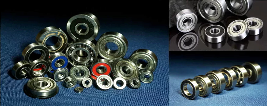
Self-aligning ball bearing
The self-aligning ball bearing is an incredibly useful tool in many industries. This type of bearing has a sealing lip that makes contact with a smooth chamfer on the inner ring. Because of the self-aligning nature of these bearings, they are not prone to misalignment. They can withstand temperatures ranging from -30°C to 120°C and should not be heated prior to installation.
A self-aligning ball bearing is an elastomer-based spherical-shaped bearing with 2 rows of rolling elements. These bearings can accommodate large radial loads, and their outer ring raceway is curved to provide a spherical effect. The inner ring, or cage, can be either cylindrical or conical. The inner diameter of a self-aligning ball bearing is normally cylindrical, but some are conical. They typically have 3 oil holes.
When choosing a self-aligning ball bearing, look for a model with a large enough bearing diameter to accommodate the shaft's bending. Self-aligning bearings may also be interchangeable with standard ball bearing assemblies. You can find individual values in manufacturer catalogues. These bearings are useful in limited applications, although they are not necessarily ideal for everything. For example, in applications where combined loads are the main concern, self-aligning ball bearings should only be used if the application requires minimal misalignment.
A self-aligning ball bearing is a highly-efficient, energy-efficient solution for a variety of applications. It is a simple, low-maintenance solution that makes your life easier. Its unique outer raceway allows restraining springs to absorb the deflection that is common in other bearings. The result is a cooler, smoother running vehicle. It also helps prevent misalignment, which makes it ideal for use in many applications.
The SKF self-aligning ball bearing is an excellent choice for applications involving heavy deflection of the shaft. They are the lowest-friction bearing available. Their steel plate reinforced seals prevent them from separating from the shaft during operation. They are also resistant to oil, making them the perfect solution for high-speed applications. In addition to this, they are designed to work in a wide range of temperatures.
Ceramic hybrid ball bearing
A hybrid ball bearing made from a combination of steel and ceramics is a good option for high-speed applications requiring electrical isolation. This combination offers an extended lifespan and minimal electrical corrosion or seizure risk. In addition, the hybrid ball bearings have less friction than steel bearings and can operate at low speeds. To learn more about this hybrid type of bearing, continue reading. We'll also discuss how it can help your application.
Full ceramic balls are generally harder than steel, but they do have lower density, meaning they're not subject to the same high centrifugal forces as steel balls. These benefits make ceramic ball bearings much more durable, with long lifespans. Both full and hybrid ceramic ball bearings are available from CZPT. Read on to learn more about each type. Here's a look at some of the benefits of each. You'll be pleasantly surprised.
A hybrid ball bearing consists of steel inner and outer rings and a ceramic ball. It can withstand high speeds and loads, but it's also designed to operate in extreme temperatures. This hybrid ball bearing also requires minimal lubrication and is suitable for a variety of applications. Because of its unique characteristics, hybrid bearings are lightweight and hard, and they spin faster than steel balls. But how do you choose the right 1 for your application?
A ceramic ball bearing is better than a steel 1 for many applications. Its greater speed capability and lower friction allow it to operate at higher speeds than steel balls. It is also less sensitive to fluctuations in lubrication conditions than steel balls. They also tend to be cheaper, so it makes sense to invest in one. It's worth your while. They last longer, and they don't require a run-in period.
A hybrid ball bearing is the best choice for electric spindles with high speed and heavy loads. A hybrid ceramic ball bearing has the advantage of low heat and high stiffness, and can operate at high speeds and loads. This thesis explores the dynamic characteristics of a hybrid ceramic ball bearing, including analysis calculations and experiment verification. The results provide reliable data and lay the foundation for professional spindle optimum design tests. It is a worthy addition to any machine shop.
China Professional CZPT Brand 3 Tons Air Hydraulic Punching Cylinder for Pressing Machine near me supplier
Product Description
Gas and liquid pressurized cylinder Product Principle
Hydro pneumatic cylinder is combined the oil pressure cylinder and booster together for taking pure gas
press as thepower source.
It makes use of the different size of booster, the crosssection area compression ratio and Pascal energy
conservation principle. Becaus of constant pressure, when the compression area change from small to
large, the press would vary with the size, so as to raise the gas pressure to tens.
Taking the prepress standard hydro pneumatic cylinder as an example: When the work gas pressed on the
hydraulic oil (or working piston)
surface, hydraulic oil would flow to the approach stroke cavity because of the air pressure, then the
hydraulic oil would promote theworkpiece to move rapidly. When the workpiece is meet the resistance
larger than the gas pressure, it stops moving. At this point, the booster cavity start moving because of the
signal (or pneumatic signal), then achieve the purpose of moding products!
Product Model information
Product Charaterics
| Item number | ULCA 1-20T output
air over oil pressure cylinder |
| Air driven | 3-8 Bar |
| Pressure | |
| Working temperatre | 0-55 degrees |
| anti-pressure of oil tank | 300 kg/cm2 |
| Working frequency | 15-25 times |
| High pressure output capacity | 1-20T |
| Installation way | From top to bottom,if need to change way ,should customize it |
Main Technical Drawing of ULCA type hydro pneumatic cylinder
Advantages of the air oil pressure cylinder
Fast speed: The action speed is faster than the hydraulic drive and it is more stability than pneumatic drive;
Easy to use: The cylinder body device is simple, so it is easy to adjust the output and facilitate to use and maintain;
High output: It can reach the highest output of oil hydraulic machine under same conditions, which can not be achieved by the pure pneumatic machine;
Low price: The price is lower than the oil pressure system;
Easy to maintain: The simple structure is easier to maintain than the oil pressure system;
Low energy consumption: When continue to boost or stop moving, it does not need the motor to keep working as the hydraulic system, then the energy can be saved. And it is convenient to take the power source, so the actual energy consumption is equivalent to 10%-30% of hydraulic power system;
No leakage: Energy conversion is easy with zero leakage, so not worry about the environmental pollution;
No harm to the die: In order to meet the technology needs, stamping pressure and the work stroke can keep within the provided area without adjustable levels;
Easy installation: There are several ways to in stall according to different work environments at any angle and position;
Soft landing: Soft-stamping technology reduce the noise to protect the die;
Fault less: No temperature rising problems unlike the hydraulic system;
Small space: Space area can be less than 50% compare with normal air cylinder and hydraulic station;
Less fault : No temperature rising problems unlike the hydraulic system;\
The energy loss comparison chart of air liquid pressurized cylinder and pneumatic cylinder
The ratio of air consumption takes hydropneumatic cylinder and pneumatic cylinder with the same output as the example: When the
working air pressure is 6kg/cm² and the diameter is 320mm, the pneumatic cylinder reaches 4800kg, but the output of hydropneumatic
cylinder is 4800kg and the diameter is 80mm. When the stroke is the same 100mm(the model of pneumatic cylinder is QGB 320*100 and
the hydropneumatic cylinder is ULCA-80-100-10E-5T), the hydro-pneumatic cylinder consumes 2575cm³ air while the pneumatic cylinder
is 15790cm³,refers to the drawing:
The examples of practical application
Worm Shafts and Gearboxes
If you have a gearbox, you may be wondering what the best Worm Shaft is for your application. There are several things to consider, including the Concave shape, Number of threads, and Lubrication. This article will explain each factor and help you choose the right Worm Shaft for your gearbox. There are many options available on the market, so don't hesitate to shop around. If you are new to the world of gearboxes, read on to learn more about this popular type of gearbox.
Concave shape
The geometry of a worm gear varies considerably depending on its manufacturer and its intended use. Early worms had a basic profile that resembled a screw thread and could be chased on a lathe. Later, tools with a straight sided g-angle were developed to produce threads that were parallel to the worm's axis. Grinding was also developed to improve the finish of worm threads and minimize distortions that occur with hardening.
To select a worm with the proper geometry, the diameter of the worm gear must be in the same unit as the worm's shaft. Once the basic profile of the worm gear is determined, the worm gear teeth can be specified. The calculation also involves an angle for the worm shaft to prevent it from overheating. The angle of the worm shaft should be as close to the vertical axis as possible.
Double-enveloping worm gears, on the other hand, do not have a throat around the worm. They are helical gears with a straight worm shaft. Since the teeth of the worm are in contact with each other, they produce significant friction. Unlike double-enveloping worm gears, non-throated worm gears are more compact and can handle smaller loads. They are also easy to manufacture.
The worm gears of different manufacturers offer many advantages. For instance, worm gears are 1 of the most efficient ways to increase torque, while lower-quality materials like bronze are difficult to lubricate. Worm gears also have a low failure rate because they allow for considerable leeway in the design process. Despite the differences between the 2 standards, the overall performance of a worm gear system is the same.
The cone-shaped worm is another type. This is a technological scheme that combines a straight worm shaft with a concave arc. The concave arc is also a useful utility model. Worms with this shape have more than 3 contacts at the same time, which means they can reduce a large diameter without excessive wear. It is also a relatively low-cost model.
Thread pattern
A good worm gear requires a perfect thread pattern. There are a few key parameters that determine how good a thread pattern is. Firstly, the threading pattern must be ACME-threaded. If this is not possible, the thread must be made with straight sides. Then, the linear pitch of the "worm" must be the same as the circular pitch of the corresponding worm wheel. In simple terms, this means the pitch of the "worm" is the same as the circular pitch of the worm wheel. A quick-change gearbox is usually used with this type of worm gear. Alternatively, lead-screw change gears are used instead of a quick-change gear box. The pitch of a worm gear equals the helix angle of a screw.
A worm gear's axial pitch must match the circular pitch of a gear with a higher axial pitch. The circular pitch is the distance between the points of teeth on the worm, while the axial pitch is the distance between the worm's teeth. Another factor is the worm's lead angle. The angle between the pitch cylinder and worm shaft is called its lead angle, and the higher the lead angle, the greater the efficiency of a gear.
Worm gear tooth geometry varies depending on the manufacturer and intended use. In early worms, threading resembled the thread on a screw, and was easily chased using a lathe. Later, grinding improved worm thread finishes and minimized distortions from hardening. As a result, today, most worm gears have a thread pattern corresponding to their size. When selecting a worm gear, make sure to check for the number of threads before purchasing it.
A worm gear's threading is crucial in its operation. Worm teeth are typically cylindrical, and are arranged in a pattern similar to screw or nut threads. Worm teeth are often formed on an axis of perpendicular compared to their parallel counterparts. Because of this, they have greater torque than their spur gear counterparts. Moreover, the gearing has a low output speed and high torque.
Number of threads
Different types of worm gears use different numbers of threads on their planetary gears. A single threaded worm gear should not be used with a double-threaded worm. A single-threaded worm gear should be used with a single-threaded worm. Single-threaded worms are more effective for speed reduction than double-threaded ones.
The number of threads on a worm's shaft is a ratio that compares the pitch diameter and number of teeth. In general, worms have 1,2,4 threads, but some have three, five, or six. Counting thread starts can help you determine the number of threads on a worm. A single-threaded worm has fewer threads than a multiple-threaded worm, but a multi-threaded worm will have more threads than a mono-threaded planetary gear.
To measure the number of threads on a worm shaft, a small fixture with 2 ground faces is used. The worm must be removed from its housing so that the finished thread area can be inspected. After identifying the number of threads, simple measurements of the worm's outside diameter and thread depth are taken. Once the worm has been accounted for, a cast of the tooth space is made using epoxy material. The casting is moulded between the 2 tooth flanks. The V-block fixture rests against the outside diameter of the worm.
The circular pitch of a worm and its axial pitch must match the circular pitch of a larger gear. The axial pitch of a worm is the distance between the points of the teeth on a worm's pitch diameter. The lead of a thread is the distance a thread travels in 1 revolution. The lead angle is the tangent to the helix of a thread on a cylinder.
The worm gear's speed transmission ratio is based on the number of threads. A worm gear with a high ratio can be easily reduced in 1 step by using a set of worm gears. However, a multi-thread worm will have more than 2 threads. The worm gear is also more efficient than single-threaded gears. And a worm gear with a high ratio will allow the motor to be used in a variety of applications.
Lubrication
The lubrication of a worm gear is particularly challenging, due to its friction and high sliding contact force. Fortunately, there are several options for lubricants, such as compounded oils. Compounded oils are mineral-based lubricants formulated with 10 percent or more fatty acid, rust and oxidation inhibitors, and other additives. This combination results in improved lubricity, reduced friction, and lower sliding wear.
When choosing a lubricant for a worm shaft, make sure the product's viscosity is right for the type of gearing used. A low viscosity will make the gearbox difficult to actuate and rotate. Worm gears also undergo a greater sliding motion than rolling motion, so grease must be able to migrate evenly throughout the gearbox. Repeated sliding motions will push the grease away from the contact zone.
Another consideration is the backlash of the gears. Worm gears have high gear ratios, sometimes 300:1. This is important for power applications, but is at the same time inefficient. Worm gears can generate heat during the sliding motion, so a high-quality lubricant is essential. This type of lubricant will reduce heat and ensure optimal performance. The following tips will help you choose the right lubricant for your worm gear.
In low-speed applications, a grease lubricant may be sufficient. In higher-speed applications, it's best to apply a synthetic lubricant to prevent premature failure and tooth wear. In both cases, lubricant choice depends on the tangential and rotational speed. It is important to follow manufacturer's guidelines regarding the choice of lubricant. But remember that lubricant choice is not an easy task.
China factory Cement Roll Press Machine Hydraulic Cylinder near me shop
Product Description
Product Description
|
Material Standard |
GB, EN, DIN, ASTM, GOST, JIS, ISO |
||
|
Material Processing |
Forging, Casting, Welding |
||
|
Heat Treatment |
Annealing, Normalizing, Q&T, Induction Hardening |
||
|
Machining Tolerance |
Max. 0.01mm |
||
|
Machining Roughness |
Max. Ra 0.4 |
||
|
Module of Gear |
8-60 |
||
|
Accuracy of Teeth |
Max. ISO Grade 5 |
||
|
Weight/Unit |
100kgs - 60 000kgs |
||
|
Application |
Mining, Cement, Construction, Chemical, Oil Drilling, Steel Mill, Sugar Mill and Power Plant |
||
|
Certification |
ISO 9001 |
||
|
OEM AND ODM SERVICE ARE OFFERED |
|||
Strictly quality inspection system can produce high quality products.
For each order,we can provide report for material chemical testing,UT testing, hardness testing ,mechanical property testing, size inspection,etc.
Production scenarios
Packaging & Shipping
In order to avoid the finish products rusted and damaged during the transportation ,we will design the right packing according to the shape,size and usage of the products.
FAQ
Q: Are you trading company or manufacturer ?
A: We are factory and trading company
Q: How long is your delivery time?
A: Generally it is 5-10 days if the goods are in stock. or it is 15-20 days if the goods are not in stock, it is according to quantity.
Q: Do you provide samples ? is it free or extra ?
A: Yes, we could offer the sample for free charge but do not pay the cost of freight.
Q: What is your terms of payment ?
A: Payment=1000USD, 30% T/T in advance ,balance before shippment.
If you have another question, pls feel free to contact us as below:
Types of Pulley Systems
If you've ever tried to lift a pail of water, you've probably seen the pulley system in action. Pulleys are extremely useful tools for everything from household appliances to heavy industrial machinery. Different kinds of pulley systems are classified according to their amount of motion. Some types have fixed axes, while others have movable axes. Some common uses of pulleys are listed below.
two-wheel pulley
Pulleys are complex structures with thin-walled and thick-walled sections. Therefore, they require specific forging designs. The tool concept for the production of pulleys is shown in Figure 11.6. Using the generated tool, the pulley can be forged into different shapes. Process parameters must be optimized based on material, surface quality and metallographic analysis.
Pulleys are wheels mounted on shafts. Its main function is to assist the movement of heavy objects. A single-wheel pulley can change the direction of the force, enabling a person to pull heavy objects. A dual-wheel pulley distributes the weight evenly across both wheels, allowing it to lift the same weight with half the effort.
The mechanical advantage of a two-wheel pulley is that it reduces the force required by about half. A 100 kg object can be lifted with a force of 500 Newtons. The mechanical advantage of a pulley with 2 wheels is twice that of a single-wheel pulley. However, care should always be taken when using two-wheel pulleys.
Two-wheel pulleys can be fixed or movable. A single wheel pulley can only change direction when the load is placed on 1 side of the wheel. Two-wheel pulleys change direction when lifting a load, requiring half the force. Live wheels are better for heavier loads. The movable pulley can be adjusted with the load, and the load distribution is more uniform. Active pulleys can be used with single-rope or two-wheel pulleys.
A pulley system with 2 wheels is called a compound pulley. This type of pulley system has a complex design that reduces the force required to move the load. Two-wheel pulleys are common in industrial and construction environments. These pulleys require a lot of space to install and operate. Additionally, they require regular maintenance to avoid wear and tear.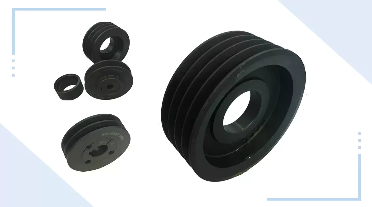
composite pulley
Compound pulleys are used to increase lift. One fixed pulley is attached to the overhead while the other fixed pulley is attached to the load. This setup minimizes the force required to lift weights, allowing you to lift heavier weights. There are several different types of compound pulleys, each with their own strengths and weaknesses. Below are some examples of their application. Some of the most common are listed below.
Composite pulleys are usually made from 2 different types of wheels. The first 1 is fixed and secure. The second type, movable, is attached to something that moves. The third type, compound pulley, is a combination of a movable pulley and a fixed pulley. Below are 3 types of comparisons. The table below compares them and explains their advantages and disadvantages. Composite pulleys are the most versatile of the three.
The number of sheave segments that make up the composite sheave system increases the mechanical advantage of the system. Each segment adds 1 percent of the total weight, and the ideal mechanical advantage is 2 or more. So a compound pulley with 4 segments will lift three-quarters of the weight. This is because the force applied to the load is multiplied by four. The result is a better boost.
While composite pulleys have many uses, they are most commonly used on larger sailboats. These pulleys work by changing the direction of the control wire or by changing the mechanical force of the rope. They also make it easier to lift heavier objects. Composite pulleys are more expensive than simple pulleys, so consider your needs before buying. The advantages of composite pulleys outweigh the disadvantages.
A basic compound pulley is a device consisting of 2 wheels with fixed points. Ropes are looped around the wheels and are used to lift heavy objects. When you pull on the rope, the rope pulls the 2 wheels closer together. Serious injury could result if this equipment is installed incorrectly. Never exceed the lifting capacity of pulleys and other safety devices that may be attached. When using pulleys, be sure to follow the instructions on the mounting hardware to avoid accidents.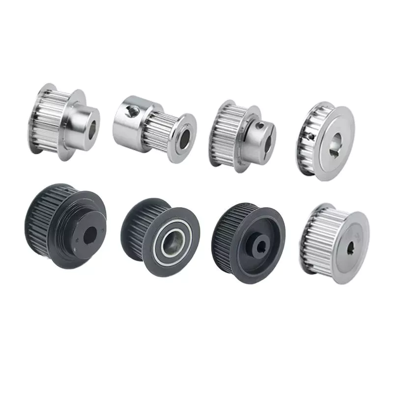
Fixed pulley
Moving pulleys and fixed pulleys are different types of mechanical devices. The movable pulley moves with the object it is used to lift. Because it attaches to the object it is used to lift, it is great for lifting heavy objects. These devices are used in construction cranes and multipurpose elevators. There are many different types of pulleys, and their uses vary widely. Below is a brief overview of these devices.
The simplest pulley set consists of a wheel that is mounted on the ceiling. A rope is attached at 1 end and a person pulls at the other end. The rope is strong enough to keep a person standing while lifting weights. It takes about 200 Newtons of force to lift a 20 kg weight. In contrast, a movable pulley requires a force of 1000N, which makes it easier to lift heavy objects.
Fixed pulleys are another common lifting device. They work by using ropes and slotted wheels attached to the object to be lifted. These devices are convenient to use because they are easy to set up. Moving the scroll wheel doesn't change direction, so it's easier to move objects without putting too much pressure on the back. Unlike a moving rope, a moving object will feel much lighter than its actual weight.
Fixed pulleys are widely used in construction and agriculture. Fixed pulleys can help lift supplies and equipment from scaffolding. These items are often heavy and difficult to lift directly. Fixed pulleys at the top of the scaffolding will allow people at the bottom to lift objects more easily. As a result, those at the bottom are less stressed and more productive. Fixed pulleys will save time and money compared to moving ropes.
Composite pulleys combine fixed and movable pulleys to increase the power of movement. A compound pulley system uses both types of pulleys and enables a person to change direction by reversing the direction of a force. The compound pulley system will save time and effort as the user only has to put in half the effort. Unlike moving ropes, composite pulleys are easy to adjust and are the most versatile system on the market.
Blocks and tackles
A pulley block system is a rope hoist that uses a set of pulleys mounted on a frame. The blocks are arranged in a row, and the threaded rope is called a pulley. Pulley systems help amplify the tension of the rope and are common in sailboats, cranes and drilling rigs. However, these systems are not without drawbacks.
The pulley pulley system can be equipped with as many pulleys as required. This method allows a person to lift heavy objects. The pulley block system can contain the required number of pulleys to achieve the desired height. The main disadvantage of pulley systems is that they create a lot of friction on the pulley shaft.
Pulley systems use 2 types of pulleys. A movable pulley is attached to the load, allowing it to move with the load. On the other hand, fixed pulleys are fixed on fixed points. Therefore, a pulley block system may consist of multiple pulleys mounted on a shaft. For example, the 2 pulleys attached to the shaft each have their own mechanical advantages.
Several types of tackle systems have been developed in recent centuries. The most basic is the gun mount, which uses 2 pulleys to lift the load. The mechanical advantage of such a system is 2 to 3 times the distance required by the rope to move the load. Depending on how they're assembled, the system can lift 400 pounds with 80 or 100 pounds of force.
Another type of pulley is a combination of multiple wheels. The wheels on pulleys are supported by a housing or frame. The chain is attached to the pulley, and the rope is pulled to lift it. A combined pulley system will have multiple wheels. As the load increases, the force on the pulley also increases. This approach is generally more expensive than intercept and intercept systems.
China Standard 900t CZPT Crack Machine Hydraulic Rock Splitter Cylinder near me factory
Product Description
900t CZPT crack machine hydraulic rock splitter cylinder
Product description:
Hydraulic CZPT Splitter is used to split rock, stone, wall and concrete construction,
which is a kind of machine to crack the rock,and that mostly used for construction, ore extraction, engineering construction It is widely used in mineral mining, civil engineering construction, demolition of buildings, river dredging and so on.
Working principle:
When the machine is working, the pump station outputs high-pressure oil to drive the cylinder, which generates a huge thrust. When the high-pressure oil outputted by the hydraulic station pushes the middle wedge of the splitting gun forward, the side wedges are spread to both sides, and the object is split in a predetermined direction in a short time.
Parameters:
|
Piston Stroke (mm) |
90/220 |
90/220 |
90/220 |
|
Drilling Depth (mm) |
>500 |
>700 |
>900 |
|
Drilling Diameter (mm) |
25 |
35 |
45 |
|
Crack Width (mm) |
10-20 |
10-20 |
10-20 |
|
Splitting Time (s) |
10-15 |
10-15 |
10-15 |
|
Splitting Force (T) |
500 |
800 |
1000 |
Product features:
1.No explosion, pollution and noise spread while working.
2. Fast cracking within several seconds, very high efficiency.
3.Dust free and near silent operation, light weight and easy operation.
4.Fast cracking within several seconds, high efficiency.
5.Enormous splitting force up to 500 tons,vibration free,and can work continuously without interruption.
6.Splitting machine can pre-determine the precise direction of division,splitting the shape and size of the part required, high division accuracy.
7.Powerful while splitting concrete or rock.
Product show :
working show :
Packaging :
About us :
ZheJiang CZPT Machinery Co., Ltd. is a large machinery manufacturing enterprise which focuses on research and development, production and sales of mining, tunnel construction, road and bridge construction equipments and so on.
We believes that good quality can give us survival, thus we only provide you top products. All the products with high quality meet international standards and are highly estimated by all clients at home and abroad.
All the staff in our company are professionally trained, so we can recommend you the most appropriate equipment. Every machine will be strictly examined before delivery. Any question about the machine will be replied within 24 hours. Welcome you to be our new client!
Certification:
Our team:
Contact us :
How to Determine the Quality of a Worm Shaft
There are many advantages of a worm shaft. It is easier to manufacture, as it does not require manual straightening. Among these benefits are ease of maintenance, reduced cost, and ease of installation. In addition, this type of shaft is much less prone to damage due to manual straightening. This article will discuss the different factors that determine the quality of a worm shaft. It also discusses the Dedendum, Root diameter, and Wear load capacity.
Root diameter
There are various options when choosing worm gearing. The selection depends on the transmission used and production possibilities. The basic profile parameters of worm gearing are described in the professional and firm literature and are used in geometry calculations. The selected variant is then transferred to the main calculation. However, you must take into account the strength parameters and the gear ratios for the calculation to be accurate. Here are some tips to choose the right worm gearing.
The root diameter of a worm gear is measured from the center of its pitch. Its pitch diameter is a standardized value that is determined from its pressure angle at the point of zero gearing correction. The worm gear pitch diameter is calculated by adding the worm's dimension to the nominal center distance. When defining the worm gear pitch, you have to keep in mind that the root diameter of the worm shaft must be smaller than the pitch diameter.
Worm gearing requires teeth to evenly distribute the wear. For this, the tooth side of the worm must be convex in the normal and centre-line sections. The shape of the teeth, referred to as the evolvent profile, resembles a helical gear. Usually, the root diameter of a worm gear is more than a quarter inch. However, a half-inch difference is acceptable.
Another way to calculate the gearing efficiency of a worm shaft is by looking at the worm's sacrificial wheel. A sacrificial wheel is softer than the worm, so most wear and tear will occur on the wheel. Oil analysis reports of worm gearing units almost always show a high copper and iron ratio, suggesting that the worm's gearing is ineffective.
Dedendum
The dedendum of a worm shaft refers to the radial length of its tooth. The pitch diameter and the minor diameter determine the dedendum. In an imperial system, the pitch diameter is referred to as the diametral pitch. Other parameters include the face width and fillet radius. Face width describes the width of the gear wheel without hub projections. Fillet radius measures the radius on the tip of the cutter and forms a trochoidal curve.
The diameter of a hub is measured at its outer diameter, and its projection is the distance the hub extends beyond the gear face. There are 2 types of addendum teeth, 1 with short-addendum teeth and the other with long-addendum teeth. The gears themselves have a keyway (a groove machined into the shaft and bore). A key is fitted into the keyway, which fits into the shaft.
Worm gears transmit motion from 2 shafts that are not parallel, and have a line-toothed design. The pitch circle has 2 or more arcs, and the worm and sprocket are supported by anti-friction roller bearings. Worm gears have high friction and wear on the tooth teeth and restraining surfaces. If you'd like to know more about worm gears, take a look at the definitions below.
CZPT's whirling process
Whirling process is a modern manufacturing method that is replacing thread milling and hobbing processes. It has been able to reduce manufacturing costs and lead times while producing precision gear worms. In addition, it has reduced the need for thread grinding and surface roughness. It also reduces thread rolling. Here's more on how CZPT whirling process works.
The whirling process on the worm shaft can be used for producing a variety of screw types and worms. They can produce screw shafts with outer diameters of up to 2.5 inches. Unlike other whirling processes, the worm shaft is sacrificial, and the process does not require machining. A vortex tube is used to deliver chilled compressed air to the cutting point. If needed, oil is also added to the mix.
Another method for hardening a worm shaft is called induction hardening. The process is a high-frequency electrical process that induces eddy currents in metallic objects. The higher the frequency, the more surface heat it generates. With induction heating, you can program the heating process to harden only specific areas of the worm shaft. The length of the worm shaft is usually shortened.
Worm gears offer numerous advantages over standard gear sets. If used correctly, they are reliable and highly efficient. By following proper setup guidelines and lubrication guidelines, worm gears can deliver the same reliable service as any other type of gear set. The article by Ray Thibault, a mechanical engineer at the University of Virginia, is an excellent guide to lubrication on worm gears.
Wear load capacity
The wear load capacity of a worm shaft is a key parameter when determining the efficiency of a gearbox. Worms can be made with different gear ratios, and the design of the worm shaft should reflect this. To determine the wear load capacity of a worm, you can check its geometry. Worms are usually made with teeth ranging from 1 to 4 and up to twelve. Choosing the right number of teeth depends on several factors, including the optimisation requirements, such as efficiency, weight, and centre-line distance.
Worm gear tooth forces increase with increased power density, causing the worm shaft to deflect more. This reduces its wear load capacity, lowers efficiency, and increases NVH behavior. Advances in lubricants and bronze materials, combined with better manufacturing quality, have enabled the continuous increase in power density. Those 3 factors combined will determine the wear load capacity of your worm gear. It is critical to consider all 3 factors before choosing the right gear tooth profile.
The minimum number of gear teeth in a gear depends on the pressure angle at zero gearing correction. The worm diameter d1 is arbitrary and depends on a known module value, mx or mn. Worms and gears with different ratios can be interchanged. An involute helicoid ensures proper contact and shape, and provides higher accuracy and life. The involute helicoid worm is also a key component of a gear.
Worm gears are a form of ancient gear. A cylindrical worm engages with a toothed wheel to reduce rotational speed. Worm gears are also used as prime movers. If you're looking for a gearbox, it may be a good option. If you're considering a worm gear, be sure to check its load capacity and lubrication requirements.
NVH behavior
The NVH behavior of a worm shaft is determined using the finite element method. The simulation parameters are defined using the finite element method and experimental worm shafts are compared to the simulation results. The results show that a large deviation exists between the simulated and experimental values. In addition, the bending stiffness of the worm shaft is highly dependent on the geometry of the worm gear toothings. Hence, an adequate design for a worm gear toothing can help reduce the NVH (noise-vibration) behavior of the worm shaft.
To calculate the worm shaft's NVH behavior, the main axes of moment of inertia are the diameter of the worm and the number of threads. This will influence the angle between the worm teeth and the effective distance of each tooth. The distance between the main axes of the worm shaft and the worm gear is the analytical equivalent bending diameter. The diameter of the worm gear is referred to as its effective diameter.
The increased power density of a worm gear results in increased forces acting on the corresponding worm gear tooth. This leads to a corresponding increase in deflection of the worm gear, which negatively affects its efficiency and wear load capacity. In addition, the increasing power density requires improved manufacturing quality. The continuous advancement in bronze materials and lubricants has also facilitated the continued increase in power density.
The toothing of the worm gears determines the worm shaft deflection. The bending stiffness of the worm gear toothing is also calculated by using a tooth-dependent bending stiffness. The deflection is then converted into a stiffness value by using the stiffness of the individual sections of the worm shaft. As shown in figure 5, a transverse section of a two-threaded worm is shown in the figure.