Product Description
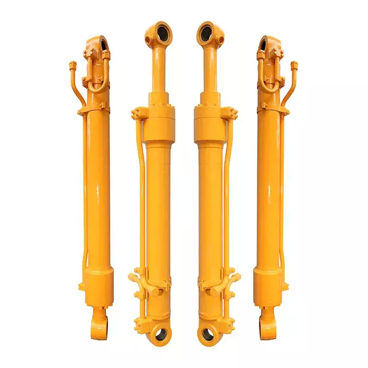
Master Hydraulic Cylinder for Press Vertical Injection Molding Machine
Product Specifications :
| Item | Specifications |
| Plunger | 500mm-1800mm,customizable |
| Stroke | 500mm-4500mm,customizable |
| Working Pressure | 7-45Mpa,customizable |
| Surface treatment of piston rod | HaHard Chrome Plating,Electroplated Milky White Chromium+Hard Chromium,Nickel Plating+Hard Chromium Plating,High-Velocity Oxygen-Fuel CrC NiC,Ceramic Coating,Nitriding,Laser Cladding |
| Work Pressure | Maximum 38MPa,Customizable |
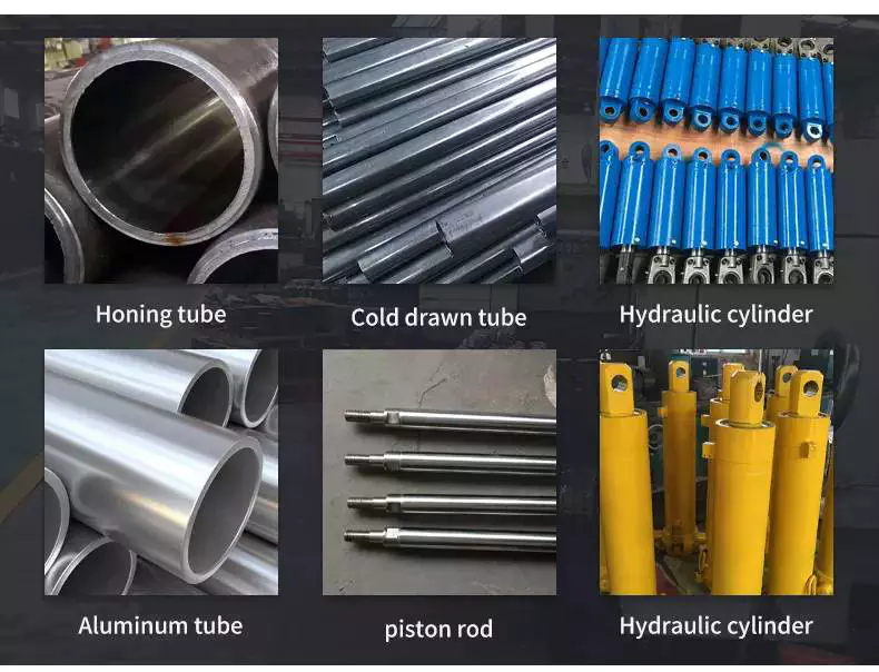
| Material | High tensile cold drawn tube, precision honed for extended seal life |
| Mounting | Earring,Flange,Clevis.Foot,Trunnion,Customizable |
| Seal Type | Parker,NOK, Hallite or as customer's requirement |
| Warrenty | 18 months |
| MOQ | 1 pcs |
| Production Time | Based on order quantity.normally 30-40 days. |
| Certification | ISO9001,CE, SGS |
| Packaging | metal case,plywood case,carton or as requirement |
| Service | OEM & ODM |
| Warranty arranwarranty ty | 18 months,customizable |
| Color | customizable |
| Price Advantage | Competitive factory price with guaranteed quality |
| Business Type | Manufacturer |
Product Display:
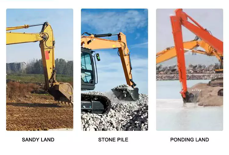
Appliactions:Construction Machinery
Mounting Method:
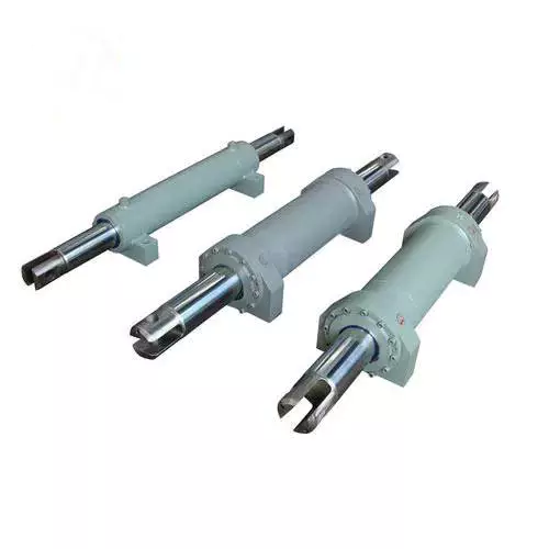
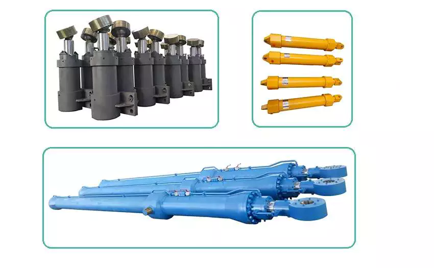
Other Related Products:
Our Factory:
Inspection Process:
| Inspection Type | Inspection Standard |
| Raw Material Inspection | Before storage, QC takes the measurement of the raw materials. |
| Process Material Inspection | During the production, QCs conduct a random inspection. Before the hydraulic cylinder parts transferred to the next process, QCs takes inspection. |
| Final Function Testing | All the hydraulic cylinders take hydraulic function test |
Inspection of Mechanical Properties of Raw Materials
Process Inspection
Final Testing
Packing & Delivery:
About US:
Our Certificate
Our Main Customers
ZheJiang Tianjian Hydraulic Technology Co.,Ltd is specializing in the production of various types of hydraulic cylinders as well as cylinder barrel, piston cylinder and other cylinder accessories.
As a highly specialized manufacturer of hydraulic cylinders, tianjian provides design optimization solutions and reliable products to many customers at home and abroad. No matter in construction machinery, railway bridge machinery, port ship machinery, metallurgy and mining machinery, oil and light industry machinery, special vehicles and other industries, tianjian can provide various standard and non-standard hydraulic cylinder design optimization schemes and products according to users' requirements, and provide integrated services for perfection and quality.
If possible, when contact with us, please apply information as below
|
Bore |
Rod |
Stroke |
Work Pressure |
Mounting |
Work environment |
|
|
|
|
|
|
|
Or you can offer us your sketch diagram or photos so that we could understand you exactly meaning, help us avoid mistakes.
And if you have samples, we can manufacture according to your samples after sending to us.
Welcome to our factory if you have any time.
Your satisfaction is our biggest motivation.
Now, you can contact with us for any question or inquiry.
FAQ:
1, What does your company do?
A: we are a supplier of high quality hydraulic products including Hydraulic Cylinder, Hydraulic Motor, Hydraulic Power Pack, Hydraulic station and other Hydraulic components.
2, Are you a manufacture or a trading company?
A: We are a manufacturer.
3, What certificate do you have?
A: All our factories are ISO certificated. And our main suppliers of materials and parts are with CE, RoHS, CSA and UL certificates.
4, How long is your delivery time?
A: The delivery time depends on different products and quantity. The cylinder usually need about 45-60 days and the Motor need about 30-50 days.
5, Can you make parts as customer's requirement or drawing?
A: Yes, we can OEM for you as your drawings. Our engineer also can give you professional support for technical suggestions.
6, What kind of payment terms do you accept?
A: We prefer T/T through bank. 30% when order is confirmed and 70% before shipment. L/C is also acceptable for amount over 20,000USD.
7, What is your warranty policy?
A: All our products are warranted for 1 full year from date of delivery against defects in materials and workmanship. This warranty does not cover parts that are worn out through the course of normal operation or are damaged through negligence. We serious remind that unclean hydraulic oil will definitely cause damage to your Hydraulic components. And this damage is not included in the warranty range. So we strongly suggest you to use new clean oil or make sure the system oil are clean when using our parts
/* March 10, 2571 17:59:20 */!function(){function s(e,r){var a,o={};try{e&&e.split(",").forEach(function(e,t){e&&(a=e.match(/(.*?):(.*)$/))&&1
| Certification: | GS, RoHS, CE, ISO9001 |
|---|---|
| Pressure: | Medium Pressure |
| Work Temperature: | High Temperature |
| Acting Way: | Double Acting |
| Working Method: | Straight Trip |
| Adjusted Form: | Regulated Type |
| Samples: |
US$ 1100/Set
1 Set(Min.Order) | |
|---|
| Customization: |
Available
|
|
|---|
Can hydraulic cylinders be retrofitted onto existing equipment for improved functionality?
Yes, hydraulic cylinders can be retrofitted onto existing equipment to enhance functionality and performance. Retrofitting hydraulic cylinders onto existing machinery or equipment offers several benefits, including increased power, improved control, enhanced precision, and versatility. Here's a detailed explanation of how hydraulic cylinders can be retrofitted onto existing equipment for improved functionality:
1. Increased Power:
- Retrofitting hydraulic cylinders allows for the addition of hydraulic power to the existing equipment. By integrating hydraulic cylinders, the equipment can generate higher forces and handle heavier loads. This increased power enables the equipment to perform tasks that were previously challenging or impossible. For example, a retrofit hydraulic cylinder on a crane can enhance its lifting capacity and enable it to handle heavier loads more efficiently.
2. Improved Control:
- Hydraulic cylinders provide precise control over the motion and positioning of equipment. By retrofitting hydraulic cylinders, operators gain better control over the speed, force, and direction of movement. The addition of hydraulic control valves and a hydraulic power unit allows for fine-tuning of the equipment's operation. Improved control facilitates safer and more efficient operation, reducing the risk of damage and improving overall productivity.
3. Enhanced Precision:
- Retrofitting hydraulic cylinders onto existing equipment can significantly improve precision and accuracy. Hydraulic systems offer precise control over movement, enabling smooth and controlled motion. This enhanced precision is beneficial in applications where precise positioning or repetitive movements are required. For instance, retrofitting hydraulic cylinders onto a robotic arm can enhance its accuracy and repeatability, making it more suitable for tasks that demand high precision.
4. Versatility and Adaptability:
- Retrofitting hydraulic cylinders can increase the versatility and adaptability of existing equipment. Hydraulic systems can be easily integrated with various types of machinery, allowing for the utilization of hydraulic power across different applications. The modular nature of hydraulic components facilitates the retrofitting process, enabling the equipment to perform a broader range of tasks. This versatility is particularly advantageous in industries where equipment needs to adapt to changing operational requirements.
5. Retrofit Kits and Customization:
- Manufacturers often provide retrofit kits that include all the necessary components for integrating hydraulic cylinders onto existing equipment. These kits typically consist of hydraulic cylinders, mounting brackets, hoses, fittings, control valves, and other required accessories. Retrofit kits simplify the retrofitting process and ensure compatibility between the hydraulic components and the existing equipment. Additionally, manufacturers can offer customization options to tailor the retrofit solution to specific equipment and application needs.
6. Cost-Effective Solution:
- Retrofitting hydraulic cylinders onto existing equipment can be a cost-effective solution compared to purchasing new machinery. By leveraging the existing equipment's structural framework and mechanical components, the overall cost of upgrading can be reduced. Retrofitting also minimizes downtime since the equipment does not need to be completely replaced. Furthermore, the improved functionality and performance resulting from the retrofit can lead to increased productivity and cost savings in the long run.
7. Professional Installation and Expertise:
- Retrofitting hydraulic cylinders onto existing equipment often requires professional installation and expertise. Working with experienced hydraulic system integrators or manufacturers ensures proper installation, compatibility, and optimal performance of the retrofit solution. These professionals can assess the existing equipment, recommend suitable hydraulic components, and carry out the retrofitting process efficiently. Their knowledge and expertise contribute to the successful integration of hydraulic cylinders and the overall improvement of equipment functionality.
In summary, hydraulic cylinders can indeed be retrofitted onto existing equipment to improve functionality. This retrofitting process offers advantages such as increased power, improved control, enhanced precision, versatility, cost-effectiveness, and access to retrofit kits and customization options. By retrofitting hydraulic cylinders, existing equipment can be upgraded to meet evolving operational needs, extend its lifespan, and enhance overall performance.
Ensuring Stable Performance of Hydraulic Cylinders Under Fluctuating Loads
Hydraulic cylinders are designed to provide stable performance even under fluctuating loads. They achieve this through various mechanisms and features that allow for efficient load control and compensation. Let's explore how hydraulic cylinders ensure stable performance under fluctuating loads:
- Piston Design: The piston inside the hydraulic cylinder plays a crucial role in load control. It is typically equipped with seals and rings that prevent leakage of hydraulic fluid and ensure effective transfer of force. The piston design may incorporate features such as stepped or tandem pistons, which provide enhanced load-bearing capabilities and improved stability by distributing the load across multiple surfaces.
- Cylinder Cushioning: Hydraulic cylinders often incorporate cushioning mechanisms to minimize the impact and shock caused by fluctuating loads. Cushioning can be achieved through various methods, such as adjustable cushion screws, hydraulic cushioning valves, or elastomeric cushioning rings. These mechanisms slow down the piston's movement near the end of the stroke, reducing the impact and preventing sudden stops that could lead to instability.
- Pressure Compensation: Fluctuating loads can result in pressure variations within the hydraulic system. To ensure stable performance, hydraulic cylinders are equipped with pressure compensation mechanisms. These mechanisms maintain a consistent pressure level in the system, regardless of load changes. Pressure compensation can be achieved through the use of pressure relief valves, compensating pistons, or pressure-compensated flow control valves.
- Flow Control: Hydraulic cylinders often incorporate flow control valves to regulate the speed of the cylinder's movement. By controlling the flow rate of hydraulic fluid, the cylinder's motion can be adjusted to match the changing load conditions. Flow control valves allow for smooth and controlled movement, preventing abrupt changes that could lead to instability.
- Feedback Systems: To ensure stable performance under fluctuating loads, hydraulic cylinders can be integrated with feedback systems. These systems provide real-time information on the cylinder's position, velocity, and force. By continuously monitoring these parameters, the hydraulic system can make immediate adjustments to maintain stability and compensate for load fluctuations. Feedback systems can include position sensors, pressure sensors, or load sensors, depending on the specific application.
- Proper Sizing and Selection: Ensuring stable performance under fluctuating loads starts with proper sizing and selection of hydraulic cylinders. It is crucial to choose cylinders with appropriate bore size, rod diameter, and stroke length to match the anticipated load conditions. Oversized or undersized cylinders can lead to instability and reduced performance. Proper sizing also involves considering factors such as the required force, speed, and duty cycle of the application.
In summary, hydraulic cylinders ensure stable performance under fluctuating loads through features such as piston design, cushioning mechanisms, pressure compensation, flow control, feedback systems, and proper sizing and selection. These mechanisms and considerations allow hydraulic cylinders to provide consistent and controlled movement, even in dynamic load conditions, resulting in reliable and stable performance.
How do hydraulic cylinders generate force and motion using hydraulic fluid?
Hydraulic cylinders generate force and motion by utilizing the principles of fluid mechanics, specifically Pascal's law, in conjunction with the properties of hydraulic fluid. The process involves the conversion of hydraulic energy into mechanical force and linear motion. Here's a detailed explanation of how hydraulic cylinders achieve this:
1. Pascal's Law:
- Hydraulic cylinders operate based on Pascal's law, which states that when pressure is applied to a fluid in a confined space, it is transmitted equally in all directions. In the context of hydraulic cylinders, this means that when hydraulic fluid is pressurized, the force is evenly distributed throughout the fluid and transmitted to all surfaces in contact with the fluid.
2. Hydraulic Fluid and Pressure:
- Hydraulic systems use a specialized fluid, typically hydraulic oil, as the working medium. This fluid is stored in a reservoir and circulated through the system by a hydraulic pump. The pump pressurizes the fluid, creating hydraulic pressure that can be controlled and directed to various components, including hydraulic cylinders.
3. Cylinder Design and Components:
- Hydraulic cylinders consist of several key components, including a cylindrical barrel, a piston, a piston rod, and various seals. The barrel is a hollow tube that houses the piston and allows for fluid flow. The piston divides the cylinder into two chambers: the rod side and the cap side. The piston rod extends from the piston and provides a connection point for external loads. Seals are used to prevent fluid leakage and maintain hydraulic pressure within the cylinder.
4. Fluid Input and Motion:
- To generate force and motion, hydraulic fluid is directed into one side of the cylinder, creating pressure on the corresponding surface of the piston. This pressure is transmitted through the fluid to the other side of the piston.
5. Force Generation:
- The force generated by a hydraulic cylinder is a result of the pressure applied to a specific surface area of the piston. The force exerted by the hydraulic cylinder can be calculated using the formula: Force = Pressure × Area. The area is determined by the diameter of the piston or the piston rod, depending on which side of the cylinder the fluid is acting upon.
6. Linear Motion:
- As the pressurized hydraulic fluid acts on the piston, it generates a force that moves the piston in a linear direction within the cylinder. This linear motion is transferred to the piston rod, which extends or retracts accordingly. The piston rod can be connected to external components or machinery, allowing the generated force to perform various tasks, such as lifting, pushing, pulling, or controlling mechanisms.
7. Control and Regulation:
- The force and motion generated by hydraulic cylinders can be controlled and regulated by adjusting the flow of hydraulic fluid into the cylinder. By regulating the flow rate, pressure, and direction of the fluid, the speed, force, and direction of the cylinder's movement can be precisely controlled. This control allows for accurate positioning, smooth operation, and synchronization of multiple cylinders in complex machinery.
8. Return and Recirculation of Fluid:
- After the hydraulic cylinder completes its stroke, the hydraulic fluid on the opposite side of the piston needs to be returned to the reservoir. This is typically achieved through hydraulic valves that control the flow direction, allowing the fluid to return and be recirculated in the system for further use.
In summary, hydraulic cylinders generate force and motion by utilizing the principles of Pascal's law. Pressurized hydraulic fluid acts on the piston, creating force that moves the piston in a linear direction. This linear motion is transferred to the piston rod, allowing the generated force to perform various tasks. By controlling the flow of hydraulic fluid, the force and motion of hydraulic cylinders can be precisely regulated, contributing to their versatility and wide range of applications in machinery.


editor by CX 2023-12-22
China supplier 2500psi Double Action Hydraulic Cylinder for Press Machine vacuum pump electric
Product Description
- Product Information
- Related Products
|
HangZhou GD Machinery CO.,LTD. |
|
|
Product |
|
|
tie rod hydraulic cylinder, welded hydraulic cylinder, telescopic cylinders cylinder, flange type hydraulic cylinder, hydraulic cylinder with valve function, hydraulic power unit, Hydraulic manifold block, pneumatic fitting, |
|
|
Material |
Tube - Cold Drawn Precision seamless Tubing Mounts - Trunnion with angular Swivels |
|
Application |
Agriculture, Concrete & Asphalt, Cranes, Fire & Rescue, Forestry & Logging,Mining & Rock Crushing,Oil & Gas, Snow & Ice Control,Waste Management and Material Recycling Industry , Engineering Equipment, Special Vehicle |
|
Feature |
1.High quality with a reasonable price 2.ISO9001-2008 3.Customized specification are accepted |
|
Payment |
T/T;L/C, Paypal |
|
Port |
HangZhou ,China |
|
Quotation |
According to the specific request |
|
MOQ |
According to the product |
|
Packaging |
metal case;plywood case;carton or as requirement |
|
Delivery time |
30days upon receipt of 30% deposit; or upon receipt of relevant L/C; |
- Our Service
1. Sample service: samples will be provided according to customer's instruction.
2. Customized services: a variety of cylinders can be customized according to customer demand.
3. Warranty service: In case of quality problems under 1 year warranty period, free replacement will be made for customer.
- Working Process
- Packing and Shipping
The products are fully protected by metal shelves, wood boxes and plastic fillers.
- Company Information
HangZhou GD Machinery is specialized to offer high precision all kind of hydraulic valves and hydraulic cylinder.we also have some hydraulic valve from CHINAMFG brand aboard
With a wide range, good quality ,reasonable price,our products are extensively used in the industries of construction machinery,machine tool,plastic machinery,vehicle. mining equipment,metallurgy,shipyard,food machinery,agricultural machinery,and other industries.
Our products are widely recognized and trusted by users and can meet continuously changing economic and social needs.
Welcome new and old customers to contact us for future business. we will offer you good quality and best price.
- Company Show
- FAQ
Q: Do you accept OEM manufacturing?
A: Yes! We do accept OEM manufacturing. We will quote you the exact price and make the exact cylinder according to your specification and drawing.
Q: Can we design our own package or print our own logo?
A: Yes! Package and logo will be made acording to your requirements.
Q: Could we get small quantity samples?
A: Yes! We understand the quality test is important and we are glad to make the sample for you. The MOQ is 1pcs.
Q: How long is the production time?
A: Generally the production time is 30 days.
Q: What is your payment term?
A: For sample payment, generally 100% T/T payment in advance, west union, paypal.
For order payment, generally is 30% T/T in advance, 70% balance before shipment. If you require the different payment term, let us negotiate it together.
| Application: | Construction Machine |
|---|---|
| Cylinder Material: | 20#/45# Steel |
| Seals: | Parker Hallite |
| Samples: |
US$ 60/Piece
1 Piece(Min.Order) | Order Sample |
|---|
| Customization: |
Available
|
|
|---|
.shipping-cost-tm .tm-status-off{background: none;padding:0;color: #1470cc}
| Shipping Cost:
Estimated freight per unit. |
about shipping cost and estimated delivery time. |
|---|
| Payment Method: |
|
|---|---|
|
Initial Payment Full Payment |
| Currency: | US$ |
|---|
| Return&refunds: | You can apply for a refund up to 30 days after receipt of the products. |
|---|
How do hydraulic cylinders compare to other methods of force generation like electric motors?
Hydraulic cylinders and electric motors are two different methods of force generation with distinct characteristics and applications. While both hydraulic cylinders and electric motors can generate force, they differ in terms of their working principles, performance attributes, and suitability for specific applications. Here's a detailed comparison of hydraulic cylinders and electric motors:
1. Working Principle:
- Hydraulic Cylinders: Hydraulic cylinders generate force through the conversion of fluid pressure into linear motion. They consist of a cylinder barrel, piston, piston rod, and hydraulic fluid. When pressurized hydraulic fluid enters the cylinder, it pushes against the piston, causing the piston rod to extend or retract, thereby generating linear force.
- Electric Motors: Electric motors generate force through the conversion of electrical energy into rotational motion. They consist of a stator, rotor, and electromagnetic field. When an electrical current is applied to the motor's windings, it creates a magnetic field that interacts with the rotor, causing it to rotate and generate torque.
2. Force and Power:
- Hydraulic Cylinders: Hydraulic cylinders are known for their high force capabilities. They can generate substantial linear forces, making them suitable for heavy-duty applications that require lifting, pushing, or pulling large loads. Hydraulic systems can provide high force output even at low speeds, allowing for precise control over force application. However, hydraulic systems typically operate at lower speeds compared to electric motors.
- Electric Motors: Electric motors excel in providing high rotational speeds and are commonly used for applications that require rapid motion. While electric motors can generate significant torque, they tend to have lower force output compared to hydraulic cylinders. Electric motors are suitable for applications that involve continuous rotary motion, such as driving conveyor belts, rotating machinery, or powering vehicles.
3. Control and Precision:
- Hydraulic Cylinders: Hydraulic systems offer excellent control over force, speed, and positioning. By regulating the flow of hydraulic fluid, the force and speed of hydraulic cylinders can be precisely controlled. Hydraulic systems can provide gradual acceleration and deceleration, allowing for smooth and precise movements. This level of control makes hydraulic cylinders well-suited for applications that require precise positioning, such as in industrial automation or construction equipment.
- Electric Motors: Electric motors also offer precise control over speed and positioning. Through motor control techniques such as varying voltage, frequency, or pulse width modulation (PWM), the rotational speed and position of electric motors can be accurately controlled. Electric motors are commonly used in applications that require precise speed control, such as robotics, CNC machines, or servo systems.
4. Efficiency and Energy Consumption:
- Hydraulic Cylinders: Hydraulic systems can be highly efficient, especially when properly sized and designed. However, hydraulic systems typically have higher energy losses due to factors such as fluid leakage, friction, and heat generation. The overall efficiency of a hydraulic system depends on the design, component selection, and maintenance practices. Hydraulic systems require a hydraulic power unit to pressurize the hydraulic fluid, which consumes additional energy.
- Electric Motors: Electric motors can have high efficiency, especially when operated at their optimal operating conditions. Electric motors have lower energy losses compared to hydraulic systems, primarily due to the absence of fluid leakage and lower friction losses. The overall efficiency of an electric motor depends on factors such as motor design, load conditions, and control techniques. Electric motors require an electrical power source, and their energy consumption depends on the motor's power rating and the duration of operation.
5. Environmental Considerations:
- Hydraulic Cylinders: Hydraulic systems typically use hydraulic fluids that can pose environmental concerns if they leak or are not properly disposed of. The choice of hydraulic fluid can impact factors such as biodegradability, toxicity, and potential environmental hazards. Proper maintenance and leak prevention practices are essential to minimize the environmental impact of hydraulic systems.
- Electric Motors: Electric motors are generally considered more environmentally friendly since they do not require hydraulic fluids. However, the environmental impact of electric motors depends on the source of electricity used to power them. When powered by renewable energy sources, such as solar or wind, electric motors can offer a greener solution compared to hydraulic systems.
6. Application Suitability:
- Hydraulic Cylinders: Hydraulic cylinders are commonly used in applications that require high force output, precise control, and durability. They are widely employed in industries such as construction, manufacturing, mining, and aerospace. Hydraulic systems are well-suited for heavy-duty applications, such as lifting heavy objects, operating heavy machinery, or controlling large-scale movements.
- Electric Motors: Electric motors are widely used in various industries and applications that require rotational motion, speed control, and precise positioning. They are commonly found in appliances, transportation, robotics, HVAC systems, and automation. Electric motorsare suitable for applications that involve continuous rotary motion, such as driving conveyor belts, rotating machinery, or powering vehicles.In summary, hydraulic cylinders and electric motors have different working principles, force capabilities, control characteristics, efficiency levels, and application suitability. Hydraulic cylinders excel in providing high force output, precise control, and durability, making them ideal for heavy-duty applications. Electric motors, on the other hand, offer high rotational speeds, precise speed control, and are commonly used for applications that involve continuous rotary motion. The choice between hydraulic cylinders and electric motors depends on the specific requirements of the application, including the type of motion, force output, control precision, and environmental considerations.
Ensuring Stable Performance of Hydraulic Cylinders Under Fluctuating Loads
Hydraulic cylinders are designed to provide stable performance even under fluctuating loads. They achieve this through various mechanisms and features that allow for efficient load control and compensation. Let's explore how hydraulic cylinders ensure stable performance under fluctuating loads:
- Piston Design: The piston inside the hydraulic cylinder plays a crucial role in load control. It is typically equipped with seals and rings that prevent leakage of hydraulic fluid and ensure effective transfer of force. The piston design may incorporate features such as stepped or tandem pistons, which provide enhanced load-bearing capabilities and improved stability by distributing the load across multiple surfaces.
- Cylinder Cushioning: Hydraulic cylinders often incorporate cushioning mechanisms to minimize the impact and shock caused by fluctuating loads. Cushioning can be achieved through various methods, such as adjustable cushion screws, hydraulic cushioning valves, or elastomeric cushioning rings. These mechanisms slow down the piston's movement near the end of the stroke, reducing the impact and preventing sudden stops that could lead to instability.
- Pressure Compensation: Fluctuating loads can result in pressure variations within the hydraulic system. To ensure stable performance, hydraulic cylinders are equipped with pressure compensation mechanisms. These mechanisms maintain a consistent pressure level in the system, regardless of load changes. Pressure compensation can be achieved through the use of pressure relief valves, compensating pistons, or pressure-compensated flow control valves.
- Flow Control: Hydraulic cylinders often incorporate flow control valves to regulate the speed of the cylinder's movement. By controlling the flow rate of hydraulic fluid, the cylinder's motion can be adjusted to match the changing load conditions. Flow control valves allow for smooth and controlled movement, preventing abrupt changes that could lead to instability.
- Feedback Systems: To ensure stable performance under fluctuating loads, hydraulic cylinders can be integrated with feedback systems. These systems provide real-time information on the cylinder's position, velocity, and force. By continuously monitoring these parameters, the hydraulic system can make immediate adjustments to maintain stability and compensate for load fluctuations. Feedback systems can include position sensors, pressure sensors, or load sensors, depending on the specific application.
- Proper Sizing and Selection: Ensuring stable performance under fluctuating loads starts with proper sizing and selection of hydraulic cylinders. It is crucial to choose cylinders with appropriate bore size, rod diameter, and stroke length to match the anticipated load conditions. Oversized or undersized cylinders can lead to instability and reduced performance. Proper sizing also involves considering factors such as the required force, speed, and duty cycle of the application.
In summary, hydraulic cylinders ensure stable performance under fluctuating loads through features such as piston design, cushioning mechanisms, pressure compensation, flow control, feedback systems, and proper sizing and selection. These mechanisms and considerations allow hydraulic cylinders to provide consistent and controlled movement, even in dynamic load conditions, resulting in reliable and stable performance.
How do hydraulic cylinders contribute to the efficiency of heavy machinery like excavators?
Hydraulic cylinders play a crucial role in enhancing the efficiency and performance of heavy machinery, such as excavators. These powerful hydraulic actuators enable excavators to perform various tasks efficiently and effectively. Here's a detailed explanation of how hydraulic cylinders contribute to the efficiency of heavy machinery like excavators:
1. Force and Power:
- Hydraulic cylinders provide the necessary force and power required for the excavation process. They convert hydraulic energy from the hydraulic fluid into linear mechanical force, allowing the excavator to exert significant pushing and pulling forces. The force generated by hydraulic cylinders enables the digging arm or boom of the excavator to penetrate and break through tough materials, such as soil, rocks, or concrete, with ease and efficiency.
2. Precise Control:
- Hydraulic cylinders offer precise control over the movement of excavator components. By regulating the flow of hydraulic fluid to the cylinders, operators can control the speed, direction, and positioning of the excavator's arm, boom, bucket, and other attachments. This precise control allows operators to perform delicate operations, such as fine grading or precise material placement, with accuracy and efficiency.
3. Versatility and Adaptability:
- Hydraulic cylinders enable excavators to perform a wide range of tasks by facilitating the quick and easy interchangeability of attachments. Excavators can be equipped with various specialized attachments, including buckets, breakers, grapples, and augers, which can be efficiently connected and disconnected using hydraulic cylinders. This versatility and adaptability enhance the efficiency of excavators by enabling them to tackle different tasks without the need for extensive manual adjustments or downtime.
4. Increased Productivity:
- The power and control provided by hydraulic cylinders significantly increase the productivity of excavators. Excavators equipped with hydraulic cylinders can complete tasks more quickly and efficiently compared to manual or mechanically-driven machinery. The precise control over movements allows for faster cycle times, reduced idle time, and improved overall productivity on the worksite.
5. Enhanced Digging and Lifting Capabilities:
- Hydraulic cylinders enable excavators to perform digging and lifting operations with enhanced capabilities. The force generated by hydraulic cylinders allows excavators to dig deeper and lift heavier loads compared to other types of machinery. This increased digging and lifting capacity contributes to the efficiency of excavators by reducing the number of passes required to complete a task and improving overall productivity.
6. Durability and Reliability:
- Hydraulic cylinders are designed to withstand heavy loads, challenging operating conditions, and frequent use. They are built with robust materials, such as high-strength steel, and undergo stringent quality control measures during manufacturing. The durability and reliability of hydraulic cylinders ensure that excavators can operate efficiently even in demanding environments, minimizing downtime and maximizing productivity.
7. Energy Efficiency:
- Hydraulic systems, including hydraulic cylinders, are known for their energy efficiency. Hydraulic cylinders can deliver high force outputs while consuming relatively low amounts of hydraulic fluid. This energy efficiency translates to lower fuel consumption and reduced operating costs for excavators. The efficient use of hydraulic power contributes to the overall efficiency and sustainability of heavy machinery operations.
8. Safety:
- Hydraulic cylinders play a vital role in ensuring the safety of excavator operations. They provide controlled and predictable movements, reducing the risk of sudden or uncontrolled motions. The precise control offered by hydraulic cylinders allows operators to perform tasks safely and accurately, minimizing the chances of accidents or damage to the machinery or surrounding environment.
Overall, hydraulic cylinders are essential components that significantly contribute to the efficiency of heavy machinery like excavators. By providing force, precise control, versatility, increased productivity, enhanced capabilities, durability, energy efficiency, and safety, hydraulic cylinders enable excavators to perform a wide range of tasks efficiently and effectively in various industries, including construction, mining, and landscaping.
editor by CX 2023-12-01
China manufacturer Working Cylinder for Artificial CZPT Hydraulic Press near me manufacturer
Product Description
40Cr Steel Forging part for Forging HPHT cubic press
Forging HPHT cubic press is also called as synthetic CZPT making machine, which can realize the production of CZPT single crystal diamond, lab grown diamond, CZPT powder, CZPT sheet, etc. The spare parts including the anvil, the steel CZPT support rings, piston cylinders, cylinder beams, small plate and big plates are all comsumable parts, requiring high strength, good technique processes of heat treatments to ensure its stable enough for CZPT making.
The full-forged cylinder beam of our synthetic CZPT manufacturing machine has a long life and a five-year warranty.
Quality Control:
1. Inspecting apparatus and equipment are tested and supervised by relevant national departments on a regular basis.
2. We conduct physical and chemical inspection to raw materials.
3. All links in production are examined and properly reported.
4. We conduct loading examination to the packaging which should be applicable to rust prevention and shipment.
5. We carry out random inspection to products in the storage.
6. Each step of inspection is recorded in both image and written form.
| Name: | Block & Cylinders & Beams |
| Raw material: | carbon/stainless/alloy steel/ 40Cr |
| Min size: | 100x100x100mm |
| Max size: | 1500x1500x1500mm |
| Min weight: | 0.30kg |
| Max weight: | 20000kg |
| Heat treatment: | Normalize/Quench/tempering |
COMPANY PROFILE:
1. With 20 years of experience in the industry, Xihu (West Lake) Dis. Huang Forging Company Ltd., ZheJiang now enjoys rich experience and excellent professional reputation. Praises from the clients are not only the driving force behind us, but also the reason why we are your best choice.
2. Here at Xihu (West Lake) Dis. Huang, we have a team of scientific and technological experts; Together with the latest manufacturing equipment and managerial expertise, we can guarantee the quality of out products in an environmental-friendly manner.
3. Located in ZheJiang Province, China's natural coal mine, we enjoy the apparent geographical advantage. Therefore, while granting product quality, our company also has huge competitiveness in terms of price.
4. Decades of development has brought us at Xihu (West Lake) Dis. Huang, a notion that we do not long for growing bigger and stronger, but for meeting the demand of our clients.
5. For the steady development of our company, Xihu (West Lake) Dis. Huang has in recent years adopted scientific management, which has not only greatly enhanced the efficiency, but also maximized the benefit for our clients. Meanwhile, scientific management has been introduced in Xihu (West Lake) Dis. Huang in client management.
| FAQs: |
| 1. What details are required for a quotation? |
| Answer: Product name, Material code, Standard code, Quantity, Drawing if any, destination port, etc.. |
| 2. Can i make changes before shipment? |
| Answer: We produce upon orders, small machining changes may workable, but big changes not available. |
| 3. What are the shipping options? |
| Answer: Sea shipment from ZheJiang port, HangZhou port, even ZheJiang port; Air shipment from ZheJiang , ZheJiang ,all available with different charges. |
| 4. When will my order ship? |
| Answer: After the production and inspection finished, after your balance payment received from our side. |
| 5. How long can i get my goods? |
| Answer: About 10-30days according to different order quantity and tons. |
| 6. How can i track my order? |
| Answer: Shipment vessel voyage status would be updated timely, the location can be shown clearly on map. |
| 7. What do i do if i received a defective order? |
| Answer: Factory inspection and Thid Party Inspection both available to ensure the quality and testing before shipment. Defective goods would not have chance outleakage from our factory. |
| 8. Can i have samples before my order? |
| Answer: Yes. Sample order is workable with charge. |
| 9. What's the minimum order quantity? |
| Answer: MOQ can be as low as 1 piece. |
Our Team:
Our Certificates:
Types of Miter Gears
The different types of miter gears include Hypoid, Crown, and Spiral. To learn more, read on. In addition, you'll learn about their differences and similarities. This article will provide an overview of the different types of miter gears. You can also choose the type that fits your needs by using the guide below. After you've read it, you'll know how to use them in your project. You'll also learn how to pair them up by hand, which is particularly useful if you're working on a mechanical component.
Bevel gears
Bevel and miter gears are both used to connect 2 shafts that have different axes. In most cases, these gears are used at right angles. The pitch cone of a bevel gear has the same shape as that of a spur gear, except the tooth profile is slightly tapered and has variable depth. The pinions of a bevel gear are normally straight, but can be curved or skew-shaped. They can also have an offset crown wheel with straight teeth relative to the axis.
In addition to their industrial applications, miter gears are found in agriculture, bottling, printing, and various industrial sectors. They are used in coal mining, oil exploration, and chemical processes. They are an important part of conveyors, elevators, kilns, and more. In fact, miter gears are often used in machine tools, like forklifts and jigsaws.
When considering which gear is right for a certain application, you'll need to think about the application and the design goals. For example, you'll want to know the maximum load that the gear can carry. You can use computer simulation programs to determine the exact torque required for a specific application. Miter gears are bevel gears that are geared on a single axis, not two.
To calculate the torque required for a particular application, you'll need to know the MA of each bevel gear. Fortunately, you can now do so with CZPT. With the help of this software, you can generate 3D models of spiral bevel gears. Once you've created your model, you can then machine it. This can make your job much easier! And it's fun!
In terms of manufacturing, straight bevel gears are the easiest to produce. The earliest method for this type of gear is a planer with an indexing head. Since the development of CNC machining, however, more effective manufacturing methods have been developed. These include CZPT, Revacycle, and Coniflex systems. The CZPT uses the Revacycle system. You can also use a CNC mill to manufacture spiral bevel gears.
Hypoid bevel gears
When it comes to designing hypoid bevel gears for miter and other kinds of gears, there are several important parameters to consider. In order to produce high-quality gearings, the mounting distance between the gear teeth and the pinion must be within a predefined tolerance range. In other words, the mounting distance between the gear teeth and pinion must be 0.05 mm or less.
To make this possible, the hypoid bevel gearset mesh is designed to involve sliding action. The result is a quiet transmission. It also means that higher speeds are possible without increasing noise levels. In comparison, bevel gears tend to be noisy at high speeds. For these reasons, the hypoid gearset is the most efficient way to build miter gears. However, it's important to keep in mind that hypoid gears are not for every application.
Hypoid bevel gears are analogous to spiral bevels, but they don't have intersecting axes. Because of this, they can produce larger pinions with smooth engagement. Crown bevel gears, on the other hand, have a 90-degree pitch and parallel teeth. Their geometry and pitch is unique, and they have particular geometrical properties. There are different ways to express pitch. The diametral pitch is the number of teeth, while circumferential measurement is called the circumference.
The face-milling method is another technique used for the manufacture of hypoid and spiral bevel gears. Face-milling allows gears to be ground for high accuracy and surface finish. It also allows for the elimination of heat treatment and facilitates the creation of predesigned ease-off topographies. Face-milling increases mechanical resistance by as much as 20%. It also reduces noise levels.
The ANSI/AGMA/ISO standards for geometric dimensioning differ from the best practices for manufacturing hypoid and bevel gears. The violation of common datum surfaces leads to a number of geometrical dimensioning issues. Moreover, hypoid gears need to be designed to incorporate the base pitches of the mating pinion and the hypoid bevel gear. This is not possible without knowing the base pitch of the gear and the mating pinion.
Crown bevel gears
When choosing crown bevels for a miter gear, you will need to consider a number of factors. Specifically, you will need to know the ratio of the tooth load to the bevel gear pitch radius. This will help you choose a bevel gear that possesses the right amount of excitation and load capacity. Crown bevels are also known as helical gears, which are a combination of 2 bevel gear types.
These bevel gears differ from spiral bevels because the bevels are not intersected. This gives you the flexibility of using a larger pinion and smoother engagement. Crown bevel gears are also named for their different tooth portions: the toe, or the part of the gear closest to the bore, and the heel, or the outermost diameter. The tooth height is smaller at the toe than it is at the heel, but the height of the gear is the same at both places.
Crown bevel gears are cylindrical, with teeth that are angled at an angle. They have a 1:1 gear ratio and are used for miter gears and spur gears. Crown bevel gears have a tooth profile that is the same as spur gears but is slightly narrower at the tip, giving them superior quietness. Crown bevel gears for miter gears can be made with an offset pinion.
There are many other options available when choosing a Crown bevel gear for miter gears. The material used for the gears can vary from plastics to pre-hardened alloys. If you are concerned with the material's strength, you can choose a pre-hardened alloy with a 32-35 Rc hardness. This alloy also has the advantage of being more durable than plastic. In addition to being stronger, crown bevel gears are also easier to lubricate.
Crown bevel gears for miter gears are similar to spiral bevels. However, they have a hyperbolic, not conical, pitch surface. The pinion is often offset above or below the center of the gear, which allows for a larger diameter. Crown bevel gears for miter gears are typically larger than hypoid gears. The hypoid gear is commonly used in automobile rear axles. They are useful when the angle of rotation is 90 degrees. And they can be used for 1:1 ratios.
Spiral miter gears
Spiral bevel gears are produced by machining the face surface of the teeth. The process follows the Hertz theory of elastic contact, where the dislocations are equivalent to small significant dimensions of the contact area and the relative radii of curvature. This method assumes that the surfaces are parallel and that the strains are small. Moreover, it can reduce noise. This makes spiral bevel gears an ideal choice for high-speed applications.
The precision machining of CZPT spiral miter gears reduces backlash. They feature adjustable locking nuts that can precisely adjust the spacing between the gear teeth. The result is reduced backlash and maximum drive life. In addition, these gears are flexible enough to accommodate design changes late in the production process, reducing risk for OEMs and increasing efficiency and productivity. The advantages of spiral miter gears are outlined below.
Spiral bevel gears also have many advantages. The most obvious of these advantages is that they have large-diameter shafts. The larger shaft size allows for a larger diameter gear, but this means a larger gear housing. In turn, this reduces ground clearance, interior space, and weight. It also makes the drive axle gear larger, which reduces ground clearance and interior space. Spiral bevel gears are more efficient than spiral bevel gears, but it may be harder to find the right size for your application.
Another benefit of spiral miter gears is their small size. For the same amount of power, a spiral miter gear is smaller than a straight cut miter gear. Moreover, spiral bevel gears are less likely to bend or pit. They also have higher precision properties. They are suitable for secondary operations. Spiral miter gears are more durable than straight cut ones and can operate at higher speeds.
A key feature of spiral miter gears is their ability to resist wear and tear. Because they are constantly being deformed, they tend to crack in a way that increases their wear and tear. The result is a harder gear with a more contoured grain flow. But it is possible to restore the quality of your gear through proper maintenance. If you have a machine, it would be in your best interest to replace worn parts if they aren't functioning as they should.


China wholesaler 200 Tons C Frame Promotion Price Hydraulic Cylinder for Press 200t C Type Hydraulic Press Machine with high quality
Product Description
200 Tons C Frame Promotion Price Hydraulic Cylinder for Press 200t C Type Hydraulic Press Machine
Product Description
Product Application
The ACCURL Hydraulic press, engineered with great care for details, is a high quality machine tool. The studies made on the framework flections have allowed us to design a product that reacts in the most appropriate and responsive way to the mechanical solicitations, therefore guaranteeing a stable structure, thus a higher precision in deep drawing.
ACCURL Hydraulic press designs and manufactures 2 or 4 Uprights Type Hydraulic Drawing Presses from 600 kN to 30000 kN for deep drawing, reverse drawing, embossing, bending, hydroforming and hot forging processes, both for steel / stainless steel production in the automotive, household white, thermo-hardening, try-out/ toolmaking and other industrial applications.
Customized for your Production:
- In addition our Presses are produced on the basis of CZPT china standard or, alternatevely, on technical specifications agreed with customers.
- User-friendly control
Versatility:
- Configuration on demand
Precision:
- Force from 600 to 30.000 kN
- Monolithic and CZPT structures
- Customizable Table dimensions
- Customizable Stroke
- Safety Standards: CAT3 e CAT4
- Mold Change systems available
- Software: Siemens touch screen
Safety:
ACCURL has a strict policy for the choice of its components, on the basis of an extensive experience acquired over decades. All components are certified in accordance with European standards and their main sources are Germany, USA, Holland, Italy and Switzerland. All structural parts are calculated by the finite element method and only high quality steel S275 and S355 JR namely J2 (+ N) is used.
Reliability:
ACCURL All structural plates used are made of steel alloys ( i.e. S355 or higher), are certified and verified for chemical analysis and mechanical testing. The assembled elements are welded together and normalized, i.a.w. UNI-EN10571 regulations. The structures are designed to improve load distribution and lower associated tensions, so to minimize distortions.
Main Features
The frame is heavy-duty as well as compact and it assures precise results.It is made of high quality mild steel and it has undergone systematicmechanical processes.
• Electric welding of high precision
• Usage of high-tech boring machines for extreme precision parts
ACCURL chooses the best products to guarantee long-lasting and high-techmachines.
ACCURL selects the best components.
APPLICATIONS:
• Graphic color CNC
•The CZPT series has been designed for applications in which structural rigidity and lexibility in terms of production are the particular rerogatives required. Machines with several actions from the top or bottom or pecial solutions enable complex shapes and large dimensions to be achieved in a number of different industries, such as:
• domestic appliances
• car and vehicle bodies
• structural elements
• stainless steel sinks
• cooker tops Laser beam safety photocells
• Silent and reliable internal gear pump
• High precision optical lines
• Electrical panel with high quality components
• Start&Stop system
Deformation simulation made by CAE |
Stress points analysis |
SAFETY WORK:
ACCURL machines comply with the strictest EU regulations with referenceto safety. The devices installed guarantee thorough safety of the operatorwithout reducing the pace of work.
• The most advanced laser systems
• Safety PLCs CZPT to manage and monitor the action of the proportional valves
• Visible dual beam linked to the upper tool: should it be is interrupted, it blocks the movement of the Deep drawing
• Easy adjustment by means of a grading scale
• Constant monitoring of parameters related to safe
Details Images
Machine Frame
Name: machine frame
Brand: ACCURL
Original: CHINA
ACCURL machines are designed from the ground up by our expert engineers with only 1 goal: to build the best machines imaginable. By combining our unique machine designs with the highest quality materials available, we have achieved our objective and invented some of the most reliable and durable machines in the world!
HYBRID SYSTEM
Name: Passion for hydraulics
Brand: Bosch- Rexroth
Original: Germany
ACCURL hydraulic and electrical systems are constantly custom designed to each machine, so give the best "performances" to individual presses, depending on its use so to maintain a good relationship "cost / benefit".
Machine Parts
Name: DOUBLE XIHU (WEST LAKE) DIS.D RAM
Brand: ACCURL
The Moving Table sliding blocks, using an accurate adjustment system, ensure full contact on the guides throughout the sliding stroke, providing to the moving elements of the press the optimal parallellism accuracy.
Machine Parts
Name: Passion for hydraulics
Brand: ACCURL
The hydraulic cylinders are completely designed and built by Gigant Italia S.r.L., the liners are made of forged steel and in case of the larger size cylinders, also the stems are made from forged body so as to ensure the pistons are reliable, safe, durable and are not keen to leaks causing machine downtime.
ACCURL Softwaree.
Under tons of steel and power beats a Heart of Technology. PLC and the latest generation of I / O. All controlled by our software specifically developed to help the operator to work in a simple and immediate way.
Technology and functionality.
The design of these presses provides a robust structure in electrowelded steel that ensures stability and firmness to the machine so as to minimize the deformation during the work cycles. Components are selected only between Main and qualified suppliers that exist in the market and each press is equipped with all legal requirements and security safeguards to comply with Category 4 of the EC Machinery Directive. Through a simple selection on the machine control panel, it is possible to set various types of data such as setting molds on RAM and lower sheet press cushion, manual setting being set up production cycle up to the semi-automatic and automatic cycles in phase of active and integral production.
| Optional Equipments | 1.Movable operation panel |
| 2.Light curtain | 3.Oil cooling device |
| 4.Knock out device (hydraulic or mechanical) | 5.Rapid mold clamping mechanism |
| 6.Xihu (West Lake) Dis. rail and rolling for die change | 7.Slide locking mechanism |
View More Products,click here...
Company Profile
How to Compare Different Types of Spur Gears
When comparing different types of spur gears, there are several important considerations to take into account. The main considerations include the following: Common applications, Pitch diameter, and Addendum circle. Here we will look at each of these factors in more detail. This article will help you understand what each type of spur gear can do for you. Whether you're looking to power an electric motor or a construction machine, the right gear for the job will make the job easier and save you money in the long run.
Common applications
Among its many applications, a spur gear is widely used in airplanes, trains, and bicycles. It is also used in ball mills and crushers. Its high speed-low torque capabilities make it ideal for a variety of applications, including industrial machines. The following are some of the common uses for spur gears. Listed below are some of the most common types. While spur gears are generally quiet, they do have their limitations.
A spur gear transmission can be external or auxiliary. These units are supported by front and rear casings. They transmit drive to the accessory units, which in turn move the machine. The drive speed is typically between 5000 and 6000 rpm or 20,000 rpm for centrifugal breathers. For this reason, spur gears are typically used in large machinery. To learn more about spur gears, watch the following video.
The pitch diameter and diametral pitch of spur gears are important parameters. A diametral pitch, or ratio of teeth to pitch diameter, is important in determining the center distance between 2 spur gears. The center distance between 2 spur gears is calculated by adding the radius of each pitch circle. The addendum, or tooth profile, is the height by which a tooth projects above the pitch circle. Besides pitch, the center distance between 2 spur gears is measured in terms of the distance between their centers.
Another important feature of a spur gear is its low speed capability. It can produce great power even at low speeds. However, if noise control is not a priority, a helical gear is preferable. Helical gears, on the other hand, have teeth arranged in the opposite direction of the axis, making them quieter. However, when considering the noise level, a helical gear will work better in low-speed situations.
Construction
The construction of spur gear begins with the cutting of the gear blank. The gear blank is made of a pie-shaped billet and can vary in size, shape, and weight. The cutting process requires the use of dies to create the correct gear geometry. The gear blank is then fed slowly into the screw machine until it has the desired shape and size. A steel gear blank, called a spur gear billet, is used in the manufacturing process.
A spur gear consists of 2 parts: a centre bore and a pilot hole. The addendum is the circle that runs along the outermost points of a spur gear's teeth. The root diameter is the diameter at the base of the tooth space. The plane tangent to the pitch surface is called the pressure angle. The total diameter of a spur gear is equal to the addendum plus the dedendum.
The pitch circle is a circle formed by a series of teeth and a diametrical division of each tooth. The pitch circle defines the distance between 2 meshed gears. The center distance is the distance between the gears. The pitch circle diameter is a crucial factor in determining center distances between 2 mating spur gears. The center distance is calculated by adding the radius of each gear's pitch circle. The dedendum is the height of a tooth above the pitch circle.
Other considerations in the design process include the material used for construction, surface treatments, and number of teeth. In some cases, a standard off-the-shelf gear is the most appropriate choice. It will meet your application needs and be a cheaper alternative. The gear will not last for long if it is not lubricated properly. There are a number of different ways to lubricate a spur gear, including hydrodynamic journal bearings and self-contained gears.
Addendum circle
The pitch diameter and addendum circle are 2 important dimensions of a spur gear. These diameters are the overall diameter of the gear and the pitch circle is the circle centered around the root of the gear's tooth spaces. The addendum factor is a function of the pitch circle and the addendum value, which is the radial distance between the top of the gear tooth and the pitch circle of the mating gear.
The pitch surface is the right-hand side of the pitch circle, while the root circle defines the space between the 2 gear tooth sides. The dedendum is the distance between the top of the gear tooth and the pitch circle, and the pitch diameter and addendum circle are the 2 radial distances between these 2 circles. The difference between the pitch surface and the addendum circle is known as the clearance.
The number of teeth in the spur gear must not be less than 16 when the pressure angle is 20 degrees. However, a gear with 16 teeth can still be used if its strength and contact ratio are within design limits. In addition, undercutting can be prevented by profile shifting and addendum modification. However, it is also possible to reduce the addendum length through the use of a positive correction. However, it is important to note that undercutting can happen in spur gears with a negative addendum circle.
Another important aspect of a spur gear is its meshing. Because of this, a standard spur gear will have a meshing reference circle called a Pitch Circle. The center distance, on the other hand, is the distance between the center shafts of the 2 gears. It is important to understand the basic terminology involved with the gear system before beginning a calculation. Despite this, it is essential to remember that it is possible to make a spur gear mesh using the same reference circle.
Pitch diameter
To determine the pitch diameter of a spur gear, the type of drive, the type of driver, and the type of driven machine should be specified. The proposed diametral pitch value is also defined. The smaller the pitch diameter, the less contact stress on the pinion and the longer the service life. Spur gears are made using simpler processes than other types of gears. The pitch diameter of a spur gear is important because it determines its pressure angle, the working depth, and the whole depth.
The ratio of the pitch diameter and the number of teeth is called the DIAMETRAL PITCH. The teeth are measured in the axial plane. The FILLET RADIUS is the curve that forms at the base of the gear tooth. The FULL DEPTH TEETH are the ones with the working depth equal to 2.000 divided by the normal diametral pitch. The hub diameter is the outside diameter of the hub. The hub projection is the distance the hub extends beyond the gear face.
A metric spur gear is typically specified with a Diametral Pitch. This is the number of teeth per inch of the pitch circle diameter. It is generally measured in inverse inches. The normal plane intersects the tooth surface at the point where the pitch is specified. In a helical gear, this line is perpendicular to the pitch cylinder. In addition, the pitch cylinder is normally normal to the helix on the outside.
The pitch diameter of a spur gear is typically specified in millimeters or inches. A keyway is a machined groove on the shaft that fits the key into the shaft's keyway. In the normal plane, the pitch is specified in inches. Involute pitch, or diametral pitch, is the ratio of teeth per inch of diameter. While this may seem complicated, it's an important measurement to understand the pitch of a spur gear.
Material
The main advantage of a spur gear is its ability to reduce the bending stress at the tooth no matter the load. A typical spur gear has a face width of 20 mm and will fail when subjected to 3000 N. This is far more than the yield strength of the material. Here is a look at the material properties of a spur gear. Its strength depends on its material properties. To find out what spur gear material best suits your machine, follow the following steps.
The most common material used for spur gears is steel. There are different kinds of steel, including ductile iron and stainless steel. S45C steel is the most common steel and has a 0.45% carbon content. This type of steel is easily obtainable and is used for the production of helical, spur, and worm gears. Its corrosion resistance makes it a popular material for spur gears. Here are some advantages and disadvantages of steel.
A spur gear is made of metal, plastic, or a combination of these materials. The main advantage of metal spur gears is their strength to weight ratio. It is about 1 third lighter than steel and resists corrosion. While aluminum is more expensive than steel and stainless steel, it is also easier to machine. Its design makes it easy to customize for the application. Its versatility allows it to be used in virtually every application. So, if you have a specific need, you can easily find a spur gear that fits your needs.
The design of a spur gear greatly influences its performance. Therefore, it is vital to choose the right material and measure the exact dimensions. Apart from being important for performance, dimensional measurements are also important for quality and reliability. Hence, it is essential for professionals in the industry to be familiar with the terms used to describe the materials and parts of a gear. In addition to these, it is essential to have a good understanding of the material and the dimensional measurements of a gear to ensure that production and purchase orders are accurate.
China Professional Manual 200 Ton Deep Drawing Hydraulic Cylinder for Press with Hot selling
Product Description
200 tonManual 200 ton deep drawing hydraulic cylinder for press
The main performance characteristics:
Economical and Practical, Hydraulic press control adopts to insert set valve integrated system, decrease let out Point.Movement reliability, durable and long life span, Itis constant pressure to realize with calm in the first place and calm procedure 2 develop technology, have to insure press the function of delay time, The route of working pressure may be regulated in assigned scope, adopt buttons for centralized control, Can realization manual, Semi-automatic, automatic 3 operate form.
Application field :
This series of hydraulic press is suitable for the pressing process of plastic materials, such as stamping, bending, flanging and thin stretching, etc. It can also be used for the correction, press-fit, plastic products and powder products.
| Specification | Unit | 200T-A | 200T-AK | 200T-B | 200T-BK | 200T-C | 200T-CK |
| Nominal force | KN | 2000 | 2000 | 2000 | 2000 | 2000 | 2000 |
| Max. pressure of liquid | MPa | 25 | 25 | 25 | 25 | 25 | 25 |
| Stroke of slider | mm | 400 | 600 | 400 | 600 | 600 | 600 |
| Max. opening height | mm | 800 | 1000 | 800 | 1000 | 800 | 1000 |
| Working table size | mm*mm | 660x660 | 660x660 | 800x800 | 800x800 | 1000x1000 | 1000x1000 |
| Descent speed | mm/s | 30 | 100 | 30 | 100 | 30 | 100 |
| Working speed | mm/s | 8-12 | 6-12 | 8-12 | 6-12 | 8-12 | 6-12 |
| Return speed | mm/s | 20 | 100 | 20 | 100 | 20 | 100 |
| Motor power | KW | 7.5 | 7.5 | 7.5 | 7.5 | 7.5 | 7.5 |
| Ejecting force | KN | 35 | 35 | 35 | 35 | 35 | 35 |
| Ejecting stoke | mm | 250 | 250 | 250 | 250 | 250 | 250 |
| Weight | T | 3.8 | 4.2 | 3.8 | 4.2 | 4.7 | 5 |
Hydraulic Press System:
The hydraulic press system device is arranged on the right side of the press, with cartridge integrated system, flexible action, reliable work, good sealing performance. The hydraulic pump comprises an oil tank, a high-pressure pump, motor, cartridge valves and other components.
This machine is suitable for the pressing of bearng parts, bending, pressing and shaping of sheet metal stretching of simple parts,stretching of simple parts.Mainly used in enterprise assembly line.
ZheJiang Woda Heavy Machinery Plant is a manufacturer of hydraulic press, Our company is located in HangZhou city , ZheJiang province , China .Our factory covers 2000 square meters. There are so many high quality engineers and experienced workers in our factory. We provide high quality machines at good prices.Welcome to visit our website or contact us for more details. We follow the principle of "satisfy our customers by active innovation; perfect every product; win customers' trust with good credit and high quality". We will perfect our service and adhere to the "higher, faster, newer, stricter" working attitude. We sincerely hope to establish business relationships with your esteemed corporation.
Our machines distribute worldwide to about 20 countries where there are metal plate industry.And where there are our machines, there are good reputation and terminal user satisfaction.
Machine Model:200 Ton Hydraulic Press YQ32-200T Hydraulic Press Machine
Type of package:
The press machine surface with anti-rust treatment.
The press machine inner layer of plastic waterproof packaging.
The press machine outer layer of thick wood or steel frame fixed,And then use a synthetic board package.
Combined container transport, or separate container transport.
FAQ
Q:How about your machine quality?We are worry about the quality.
A:Woda is a mature brand in China. through our several years research in technology , our design including strcture and detailed sercurity and precision has enhanced greatly, and can match all the CE standard or mor strict standard.Our machines distribute worldwide to about 20 countries where there are metal plate industry.And where there are our machines, there are good reputation and terminal user satisfaction.
Q:Why Choose your company?
A:We can provide customized services according to customer requirements. We also have professional R &D team and fast response sales team. Strictly control each step of QA &QC system processes. We have an after sale service team than can quickly solve any problem you may have in the use.
Q:How to select your machine?
A: You can tell me your specifications ,we can choose the best model for you . we also have some regular model for you to choose.You can also provide the drawings, size , photos of the products, we can design the suitable machine for you according to your requirements. After the machine is finished, you can also provide samples and we will test it for you.
Why Checking the Drive Shaft is Important
If you hear clicking noises while driving, your driveshaft may need repair. An experienced mechanic can tell if the noise is coming from 1 side or both sides. This problem is usually related to the torque converter. Read on to learn why it's so important to have your driveshaft inspected by an auto mechanic. Here are some symptoms to look for. Clicking noises can be caused by many different things. You should first check if the noise is coming from the front or the rear of the vehicle.
hollow drive shaft
Hollow driveshafts have many benefits. They are light and reduce the overall weight of the vehicle. The largest manufacturer of these components in the world is CZPT. They also offer lightweight solutions for various applications, such as high-performance axles. CZPT driveshafts are manufactured using state-of-the-art technology. They offer excellent quality at competitive prices.
The inner diameter of the hollow shaft reduces the magnitude of the internal forces, thereby reducing the amount of torque transmitted. Unlike solid shafts, hollow shafts are getting stronger. The material inside the hollow shaft is slightly lighter, which further reduces its weight and overall torque. However, this also increases its drag at high speeds. This means that in many applications hollow driveshafts are not as efficient as solid driveshafts.
A conventional hollow drive shaft consists of a first rod 14 and a second rod 14 on both sides. The first rod is connected with the second rod, and the second rod extends in the rotation direction. The 2 rods are then friction welded to the central area of the hollow shaft. The frictional heat generated during the relative rotation helps to connect the 2 parts. Hollow drive shafts can be used in internal combustion engines and environmentally-friendly vehicles.
The main advantage of a hollow driveshaft is weight reduction. The splines of the hollow drive shaft can be designed to be smaller than the outside diameter of the hollow shaft, which can significantly reduce weight. Hollow shafts are also less likely to jam compared to solid shafts. Hollow driveshafts are expected to eventually occupy the world market for automotive driveshafts. Its advantages include fuel efficiency and greater flexibility compared to solid prop shafts.
Cardan shaft
Cardan shafts are a popular choice in industrial machinery. They are used to transmit power from 1 machine to another and are available in a variety of sizes and shapes. They are available in a variety of materials, including steel, copper, and aluminum. If you plan to install 1 of these shafts, it is important to know the different types of Cardan shafts available. To find the best option, browse the catalog.
Telescopic or "Cardan" prop shafts, also known as U-joints, are ideal for efficient torque transfer between the drive and output system. They are efficient, lightweight, and energy-efficient. They employ advanced methods, including finite element modeling (FEM), to ensure maximum performance, weight, and efficiency. Additionally, the Cardan shaft has an adjustable length for easy repositioning.
Another popular choice for driveshafts is the Cardan shaft, also known as a driveshaft. The purpose of the driveshaft is to transfer torque from the engine to the wheels. They are typically used in high-performance car engines. Some types are made of brass, iron, or steel and have unique surface designs. Cardan shafts are available in inclined and parallel configurations.
Single Cardan shafts are a common replacement for standard Cardan shafts, but if you are looking for dual Cardan shafts for your vehicle, you will want to choose the 1310 series. This type is great for lifted jeeps and requires a CV-compatible transfer case. Some even require axle spacers. The dual Cardan shafts are also designed for lifts, which means it's a good choice for raising and lowering jeeps.
universal joint
Cardan joints are a good choice for drive shafts when operating at a constant speed. Their design allows a constant angular velocity ratio between the input and output shafts. Depending on the application, the recommended speed limit may vary depending on the operating angle, transmission power, and application. These recommendations must be based on pressure. The maximum permissible speed of the drive shaft is determined by determining the angular acceleration.
Because gimbal joints don't require grease, they can last a long time but eventually fail. If they are poorly lubricated or dry, they can cause metal-to-metal contact. The same is true for U-joints that do not have oil filling capability. While they have a long lifespan, it can be difficult to spot warning signs that could indicate impending joint failure. To avoid this, check the drive shaft regularly.
U-joints should not exceed 70 percent of their lateral critical velocity. However, if this speed is exceeded, the part will experience unacceptable vibration, reducing its useful life. To determine the best U-joint for your application, please contact your universal joint supplier. Typically, lower speeds do not require balancing. In these cases, you should consider using a larger pitch diameter to reduce axial force.
To minimize the angular velocity and torque of the output shaft, the 2 joints must be in phase. Therefore, the output shaft angular displacement does not completely follow the input shaft. Instead, it will lead or lag. Figure 3 illustrates the angular velocity variation and peak displacement lead of the gimbal. The ratios are shown below. The correct torque for this application is 1360 in-Ibs.
Refurbished drive shaft
Refurbished driveshafts are a good choice for a number of reasons. They are cheaper than brand new alternatives and generally just as reliable. Driveshafts are essential to the function of any car, truck, or bus. These parts are made of hollow metal tubes. While this helps reduce weight and expense, it is vulnerable to external influences. If this happens, it may crack or bend. If the shaft suffers this type of damage, it can cause serious damage to the transmission.
A car's driveshaft is a critical component that transmits torque from the engine to the wheels. A1 Drive Shaft is a global supplier of automotive driveshafts and related components. Their factory has the capability to refurbish and repair almost any make or model of driveshafts. Refurbished driveshafts are available for every make and model of vehicle. They can be found on the market for a variety of vehicles, including passenger cars, trucks, vans, and SUVs.
Unusual noises indicate that your driveshaft needs to be replaced. Worn U-joints and bushings can cause excessive vibration. These components cause wear on other parts of the drivetrain. If you notice any of these symptoms, please take your vehicle to the AAMCO Bay Area Center for a thorough inspection. If you suspect damage to the driveshaft, don't wait another minute - it can be very dangerous.
The cost of replacing the drive shaft
The cost of replacing a driveshaft varies, but on average, this repair costs between $200 and $1,500. While this price may vary by vehicle, the cost of parts and labor is generally equal. If you do the repair yourself, you should know how much the parts and labor will cost before you start work. Some parts can be more expensive than others, so it's a good idea to compare the cost of several locations before deciding where to go.
If you notice any of these symptoms, you should seek a repair shop immediately. If you are still not sure if the driveshaft is damaged, do not drive the car any distance until it is repaired. Symptoms to look for include lack of power, difficulty moving the car, squeaking, clanking, or vibrating when the vehicle is moving.
Parts used in drive shafts include center support bearings, slip joints, and U-joints. The price of the driveshaft varies by vehicle and may vary by model of the same year. Also, different types of driveshafts require different repair methods and are much more expensive. Overall, though, a driveshaft replacement costs between $300 and $1,300. The process may take about an hour, depending on the vehicle model.
Several factors can lead to the need to replace the drive shaft, including bearing corrosion, damaged seals, or other components. In some cases, the U-joint indicates that the drive shaft needs to be replaced. Even if the bearings and u-joints are in good condition, they will eventually break and require the replacement of the drive shaft. However, these parts are not cheap, and if a damaged driveshaft is a symptom of a bigger problem, you should take the time to replace the shaft.
China Good quality Front Mount Telescopic Hydraulic Cylinder for Hydraulic Press wholesaler
Product Description
| Name | Hydraulic drawbench cylinder |
| Bore diameter | 800mm |
| Rod diameter | 400mm |
| Stroke | 10800mm |
| Working pressure | 27MPa |
| Piston rod material | CK45 |
| Bore material | CK45 |
| Numbers(MOQ) | 1 pcs |
| Package | Packing strap |
| Application | Hydraulic drawbench |
Lian Hydraulic was formed in HangZhou of China with the mission of supplying the world class hydraulic cylinders and hydraulic systems to the various industrial sectors .
Since that date our company has successfully completed numerous installations throughout the Chinese mainland and abroad.
Our factory floor space exceeds 38,000 Sqr. meters and our 20 cranes provide us with the capability to handle and machine cylinders and components weighing up to 150,000kgs.
From conception to installation our engineers, factory staff and salesmen strive to ensure that our customers receive the very best in quality products and service.
Our manufacturing facility is capable of producing hydraulic cylinders up to the following dimensions:
Bore Diameter - 2,500 mm
Rod Diameter - 1,500 mm
Stroke - 20,000 mm
The Typical Applications:
Machine Manufacturing
Casting Cylinders
Mobile Hydraulics
Press Manufacturing
Hydroelectric Industry
Offshore Industry
Mining Industry
Hydraulic Systems
Lian Hydraulic source raw materials exclusively from the most reputable and quality approved suppliers in China such as ( HangZhou Pangang, ZheJiang Valin Steel, ZheJiang Baosteel etc.)
We at Lian Hydraulic invite all customers to consider our facility for your next hydraulic project.
How to Select a Worm Shaft and Gear For Your Project
You will learn about axial pitch PX and tooth parameters for a Worm Shaft 20 and Gear 22. Detailed information on these 2 components will help you select a suitable Worm Shaft. Read on to learn more....and get your hands on the most advanced gearbox ever created! Here are some tips for selecting a Worm Shaft and Gear for your project!...and a few things to keep in mind.
Gear 22
The tooth profile of Gear 22 on Worm Shaft 20 differs from that of a conventional gear. This is because the teeth of Gear 22 are concave, allowing for better interaction with the threads of the worm shaft 20. The worm's lead angle causes the worm to self-lock, preventing reverse motion. However, this self-locking mechanism is not entirely dependable. Worm gears are used in numerous industrial applications, from elevators to fishing reels and automotive power steering.
The new gear is installed on a shaft that is secured in an oil seal. To install a new gear, you first need to remove the old gear. Next, you need to unscrew the 2 bolts that hold the gear onto the shaft. Next, you should remove the bearing carrier from the output shaft. Once the worm gear is removed, you need to unscrew the retaining ring. After that, install the bearing cones and the shaft spacer. Make sure that the shaft is tightened properly, but do not over-tighten the plug.
To prevent premature failures, use the right lubricant for the type of worm gear. A high viscosity oil is required for the sliding action of worm gears. In two-thirds of applications, lubricants were insufficient. If the worm is lightly loaded, a low-viscosity oil may be sufficient. Otherwise, a high-viscosity oil is necessary to keep the worm gears in good condition.
Another option is to vary the number of teeth around the gear 22 to reduce the output shaft's speed. This can be done by setting a specific ratio (for example, 5 or 10 times the motor's speed) and modifying the worm's dedendum accordingly. This process will reduce the output shaft's speed to the desired level. The worm's dedendum should be adapted to the desired axial pitch.
Worm Shaft 20
When selecting a worm gear, consider the following things to consider. These are high-performance, low-noise gears. They are durable, low-temperature, and long-lasting. Worm gears are widely used in numerous industries and have numerous benefits. Listed below are just some of their benefits. Read on for more information. Worm gears can be difficult to maintain, but with proper maintenance, they can be very reliable.
The worm shaft is configured to be supported in a frame 24. The size of the frame 24 is determined by the center distance between the worm shaft 20 and the output shaft 16. The worm shaft and gear 22 may not come in contact or interfere with 1 another if they are not configured properly. For these reasons, proper assembly is essential. However, if the worm shaft 20 is not properly installed, the assembly will not function.
Another important consideration is the worm material. Some worm gears have brass wheels, which may cause corrosion in the worm. In addition, sulfur-phosphorous EP gear oil activates on the brass wheel. These materials can cause significant loss of load surface. Worm gears should be installed with high-quality lubricant to prevent these problems. There is also a need to choose a material that is high-viscosity and has low friction.
Speed reducers can include many different worm shafts, and each speed reducer will require different ratios. In this case, the speed reducer manufacturer can provide different worm shafts with different thread patterns. The different thread patterns will correspond to different gear ratios. Regardless of the gear ratio, each worm shaft is manufactured from a blank with the desired thread. It will not be difficult to find 1 that fits your needs.
Gear 22's axial pitch PX
The axial pitch of a worm gear is calculated by using the nominal center distance and the Addendum Factor, a constant. The Center Distance is the distance from the center of the gear to the worm wheel. The worm wheel pitch is also called the worm pitch. Both the dimension and the pitch diameter are taken into consideration when calculating the axial pitch PX for a Gear 22.
The axial pitch, or lead angle, of a worm gear determines how effective it is. The higher the lead angle, the less efficient the gear. Lead angles are directly related to the worm gear's load capacity. In particular, the angle of the lead is proportional to the length of the stress area on the worm wheel teeth. A worm gear's load capacity is directly proportional to the amount of root bending stress introduced by cantilever action. A worm with a lead angle of g is almost identical to a helical gear with a helix angle of 90 deg.
In the present invention, an improved method of manufacturing worm shafts is described. The method entails determining the desired axial pitch PX for each reduction ratio and frame size. The axial pitch is established by a method of manufacturing a worm shaft that has a thread that corresponds to the desired gear ratio. A gear is a rotating assembly of parts that are made up of teeth and a worm.
In addition to the axial pitch, a worm gear's shaft can also be made from different materials. The material used for the gear's worms is an important consideration in its selection. Worm gears are usually made of steel, which is stronger and corrosion-resistant than other materials. They also require lubrication and may have ground teeth to reduce friction. In addition, worm gears are often quieter than other gears.
Gear 22's tooth parameters
A study of Gear 22's tooth parameters revealed that the worm shaft's deflection depends on various factors. The parameters of the worm gear were varied to account for the worm gear size, pressure angle, and size factor. In addition, the number of worm threads was changed. These parameters are varied based on the ISO/TS 14521 reference gear. This study validates the developed numerical calculation model using experimental results from Lutz and FEM calculations of worm gear shafts.
Using the results from the Lutz test, we can obtain the deflection of the worm shaft using the calculation method of ISO/TS 14521 and DIN 3996. The calculation of the bending diameter of a worm shaft according to the formulas given in AGMA 6022 and DIN 3996 show a good correlation with test results. However, the calculation of the worm shaft using the root diameter of the worm uses a different parameter to calculate the equivalent bending diameter.
The bending stiffness of a worm shaft is calculated through a finite element model (FEM). Using a FEM simulation, the deflection of a worm shaft can be calculated from its toothing parameters. The deflection can be considered for a complete gearbox system as stiffness of the worm toothing is considered. And finally, based on this study, a correction factor is developed.
For an ideal worm gear, the number of thread starts is proportional to the size of the worm. The worm's diameter and toothing factor are calculated from Equation 9, which is a formula for the worm gear's root inertia. The distance between the main axes and the worm shaft is determined by Equation 14.
Gear 22's deflection
To study the effect of toothing parameters on the deflection of a worm shaft, we used a finite element method. The parameters considered are tooth height, pressure angle, size factor, and number of worm threads. Each of these parameters has a different influence on worm shaft bending. Table 1 shows the parameter variations for a reference gear (Gear 22) and a different toothing model. The worm gear size and number of threads determine the deflection of the worm shaft.
The calculation method of ISO/TS 14521 is based on the boundary conditions of the Lutz test setup. This method calculates the deflection of the worm shaft using the finite element method. The experimentally measured shafts were compared to the simulation results. The test results and the correction factor were compared to verify that the calculated deflection is comparable to the measured deflection.
The FEM analysis indicates the effect of tooth parameters on worm shaft bending. Gear 22's deflection on Worm Shaft can be explained by the ratio of tooth force to mass. The ratio of worm tooth force to mass determines the torque. The ratio between the 2 parameters is the rotational speed. The ratio of worm gear tooth forces to worm shaft mass determines the deflection of worm gears. The deflection of a worm gear has an impact on worm shaft bending capacity, efficiency, and NVH. The continuous development of power density has been achieved through advancements in bronze materials, lubricants, and manufacturing quality.
The main axes of moment of inertia are indicated with the letters A-N. The three-dimensional graphs are identical for the seven-threaded and one-threaded worms. The diagrams also show the axial profiles of each gear. In addition, the main axes of moment of inertia are indicated by a white cross.
China Best Sales Hydraulic Cylinder for Hydraulic Press Machine with Servo Motor with Free Design Custom
Product Description
hydraulic cylinder for hydraulic press machine with servo motor
We are the factory specializing in the production of hydraulic presses.
And can provide total solutions, including hydraulic press machines, molds, product processing technology, automated production lines.
YIHUI 4 column servo hydraulic press machine is with PLC and with touch screen and with servo motor .
Touch Screen Details
Product Application
Pressing, heat pressing,Forging, Stamping, Powder Compacting, Compressing, Moulding and so on.
Parameters
| YHA5 single action servo hydraulic press specification | |||||||
| Item | Unit | Specifications | |||||
| YHA5-80T | YHA5-100T | YHA5-150T | YHA5-200T | YHA5-300T | |||
| Nominal capacity | kN | 800 | 1000 | 1500 | 2000 | 3000 | |
| Max.Working pressure | Mpa | 20 | 21 | 21 | 20 | 24 | |
| Main cylinder Force | kN | 800 | 1000 | 1500 | 2000 | 3000 | |
| Max.Stroke of ram | mm | 350 | 350 | 350 | 350 | 350 | |
| Max.Open height | mm | 450 | 450 | 550 | 600 | 650 | |
| Lower cyinder norminal force | kN | 50 | 50 | 50 | 50 | 50 | |
| Max.stroke of cushion piston | mm | 150 | 150 | 150 | 150 | 150 | |
| Speed of ram | Down no load | mm/s | 180 | 180 | 180 | 180 | 170 |
| Pressing | mm/s | 15 | 12 | 10 | 10 | 8 | |
| Return | mm/s | 170 | 170 | 170 | 170 | 165 | |
| Effective area of working table | RL(column inside) | mm | 550 | 550 | 550 | 550 | 550 |
| FB(edge) | mm | 600 | 600 | 600 | 600 | 650 | |
| Overall dimension | L.R | mm | 1550 | 1550 | 1760 | 1830 | 1420 |
| F.B | mm | 1260 | 1260 | 1260 | 1360 | 1550 | |
| H | mm | 2580 | 2580 | 2650 | 2750 | 2920 | |
| Motor power | kW | 7.5 | 7.5 | 7.5 | 11 | 15 | |
| Total weight(Approx) | Ton | 2.6 | 2.6 | 3.2 | 3.5 | 6.2 | |
| Oil quantity(Approx) | L | 300 | 360 | 360 | 400 | 450 | |
All above specifications are standard specification of hydraulic press machine,any special specifications customize is also available for us!
Component Details
Why so many famous brand company cooperate with us ?
1.Our factory have specialized in independent development and producing hydraulic press for 20 years.So the product is stable and high quality.
2. Machine body, we use bending structure , much stronger than the common welding structure .
3. Oil pipe, we use Clip-on structure , much tight than common welding structure. Prevent oil leakage.
4. We take integrated oil manifold block, much easier to check machine and repair machine.
5.The main components are imported from Germany, Italy and Japan . So the quality is near the Japan production, but the unit price is lower than Japan production.
6.Our factory can offer full set line service, such as the mould,process technology, and other relative machines.
Our Certificates
Features:
Servo motor drive system:
1. Small start-up current: little impact on power grid.
2. Motor starts when press is punching and stops when feeding material,picking out bricks,and cleaning mould. Energy-saving high to 65%.
3. High control precision: speed error is only 0.0001/r.
4. Stable running: no vibration and high torque when runs with low speed.
5. Quick response: very short time from static to rated speed, CZPT to adjust speed freely between high speed to low speed within 1 stroke. Excellent effect of even hammer strike.
6. Speed overload function, achieves 2-3 times of rated speed.
Touch screen parameter setting system:
1. According to technology demands for different bricks, user can set the strike times, strike strength, and strike speed digitally. CZPT to achieve the effect of gently press for air-released, strike from gentle to heavy, the whole process of brick producing sequencing, reduce human factor to improve product quality.
2. Touch screen can real-time display the working status, monitor the producing process, detect and report the failure automatically.
3. CZPT to set password to protect production safety.
4. Touch screen has operation instruction and guideline.
Some Overseas Customers
YIHUI Hydraulic press with servo system,can bring you 10 kinds Advantages as below:
1. Can avoid the oil leakage. Because using Servo motor, the oil temperature can be lower.
2. English and customer country local language, bilingual operation interface, easy to operate.
3.Can save 50% - 70% energy.
4.Parameters and Speed can be adjusted on the touch screen, easy to operate.(Machine without servo system, speed can not been adjusted.)
5.Can be 3 to 5 years longer service life than the common machine.
it means,if common machine can service for 10 years, then machine with servo, can use 15 years.
6.Ensure safety and easy to know error,easy to do after service. Because of Automatic alarm and auto troubleshooting system.
7.Very easy to change mold, shorter time of changing mold.
Because it have memory function,if use the original mold, do not need to adjust parameter again,
8.Very quiet , do not have noise.
9.Much stable than common machine.
10.Much high precision than common machine.
Our Company
Years of Experience
HangZhou CZPT Hydraulic Machinery Co., Ltd. has been specialized in manufacturing hydraulic press machine for over 20 years . Especially speciallized in the servo system hydraulic press machine .
Exported Countries
YIHUI brand machines have been exported to over 40 countries,
such as Germany, USA, UK, Sweden, Japan,Slovenia, Serbia,Saudi Arabia,El Salvador,Togo, Malaysia,Singapore, Australia ,Vietnam,Pakistan,South Africa, and so on.
Cooperative brand
Customers' Positive Feedback
Exhibition
Packing&Delivery
| Packing | |
| Size | Accordingly |
| Weight | Accordingly |
| Packing Details | The normal package is wooden case(Size: L*W*H). The wooden case will be fumigated if needed. If container is too tight, we will use PE film for packing or pack it according to customers' special request. |
FAQ
Q1. Are you manufacturer or Trader?
A1: We are professional in producing hydraulic press for over 20 years, We have our own designer,and the machines have been patented.
Q2. How to get an accurate quotation?
A2: The customer should provide the related technical requirements, product drawings, pictures, industrial voltage, planned output, etc.
Q3. What if I use this machine for the first time and know nothing of it ?
A3: We will have our engineers teach you how to operate it,you can just inform us some details of the product.you need then we can customize as your special order.
Q4. How does your factory do regarding quality control?
A4:HangZhou CZPT has been regard quality as the priority. We always attach great importance to quality controlling from the very beginning to the very end ,so our press can match all the CE and ISO standard also more strict standard .
Q5. How about your delivery time?
A5: Generally, it will take 35 days after receiving your deposit payment. The customized press delivery time depends on the items and the quantity of your order, in general is 55 days.Sometimes we have standard machines in stock.
Q6. What is the warrantee period of the machine?
A6: We can supply 1 year warranty for our machines, We can send engineer to customer place if big quality problem. We can provide internet or calling service at any time.
Q7. What is the after-sales service of your factory?
A7: 1.Installation:Free installation and commissioning, travel expense is on foreign customer. (Including round ticket and accommodation cost)
2.Personnel training: Our engineers will give your employees free machine training when they come to our company to assemble the machines, and welcome to our factory to learn how to operate our machine.
B7: And we can offer engineer overseas service.
Q8. What is the advantage of your factory?
A8: The main components of our machine are imported from the famous brand such as Japan and Germany. So the quality is near the Japan production, but the unit price is lower than it.
We do have a full set line service (turnkey project),which means that we can not only provide the press and mold but also able to customized as your special order.
Materials Used in Bearings
If you're not familiar with the types of bearings, you may be interested in knowing more about the materials used to manufacture them. Here's a look at what each type of bearing is made of, how it's used, and how much they cost. To find the right bearing for your application, it's important to choose a quality lubricant. The materials used in bearings are determined by their type and applications. Choosing the right lubricant will extend its life, and protect your machine's parts from damage and premature wear.
Materials used in bearings
Bearings are made from a variety of materials. Stainless steel is a common material used for the components of bearings. It has a higher content of chromium and nickel. When exposed to oxygen, chromium reacts with it to form chromium oxide, which provides a passive film. For higher temperatures, teflon and Viton are also used. These materials offer excellent corrosion resistance and are often preferred by manufacturers for their unique properties.
Stainless steel is another material used in bearings. AISI 440C is a high-carbon stainless steel commonly used in rolling-contact bearings. It is widely used in corrosive environments, especially in applications where corrosion resistance is more important than load capacity. It can also be heat-treated and hardened to 60 HRC, but has lower fatigue life than SAE 52100. Stainless steel bearings may carry a 20-40% price premium, but their superior performance is worth the extra money.
Graphite and molybdenum disulfide are 2 of the most common materials used in bearings. While graphite is a popular material in bearings, it has very poor corrosion resistance and is unsuitable for applications where oil or grease is required. Graphite-based composite materials are another option. They combine the benefits of both graphite and ceramic materials. A variety of proprietary materials have been developed for high-temperature use, such as graphite and MoS2.
Wood bearings have been around for centuries. The oldest ones used wood and Lignum Vitae. These materials were lightweight, but they were incredibly strong and durable. Wood bearings were also lubricated with animal fats. During the 1700s, iron bearings were a popular choice. In 1839, Isaac Babbitt invented an alloy containing hard metal crystals suspended in a softer metal. It is considered a metal matrix composite.
Applications of bearings
Bearings are used in many different industries and systems to help facilitate rotation. The metal surfaces in the bearings support the weight of the load, which drives the rotation of the unit. Not all loads apply the same amount of force to bearings, however. Thrust and radial loads act in distinctly different ways. To better understand the different uses of bearings, let's examine the various types of bearings. These versatile devices are essential for many industries, from automobiles to ships and from construction to industrial processes.
Cylindrical roller bearings are designed to support heavy loads. Their cylindrical rolling element distributes the load over a larger area. They are not, however, suited to handling thrust loads. Needle bearings, on the other hand, use small diameter cylinders and can fit into tighter spaces. The advantages of these types of bearings are numerous, and many leading producers are now leveraging the Industrial Internet of Things (IIoT) to develop connected smart bearings.
As a power generation industry, bearings play an essential role. From turbines to compressors, from generators to pumps, bearings are essential components of equipment. In addition to bearings, these components help move the equipment, so they can work properly. Typically, these components use ball bearings, although some roller bearings are used as well. In addition to being efficient and durable, these types of bearings also tend to be built to meet stringent internal clearance requirements and cage design requirements.
In addition to bearings for linear motion, bearings can also bear the weight of a rotary part. Depending on the application, they can be designed to minimize friction between moving parts. By constraining relative motion, bearings are used to reduce friction within a given application. The best-designed bearings minimize friction in a given application. If you're in the market for a new bearing, NRB Industrial Bearings Limited is an excellent source to begin your search.
Types of bearings
The type of bearings you choose will have a significant impact on the performance of your machinery. Using the right bearings can increase efficiency, accuracy, and service intervals, and even reduce the cost of purchasing and operating machinery. There are several different types of bearings to choose from, including ball bearings and flexure bearings. Some types use a fluid to lubricate their surfaces, while others do not.
Plain bearings are the most common type of bearing, and are used for a variety of applications. Their cylindrical design allows for a relatively smooth movement. Often made of copper or other copper alloy, they have low coefficients of friction and are commonly used in the construction industry. Some types of plain bearings are also available with a gudgeon pin, which connects a piston to a connecting rod in a diesel engine.
Magnetic bearings are the newest type of bearing. They use permanent magnets to create a magnetic field around the shaft without requiring any power. These are difficult to design, and are still in the early stages of development. Electromagnets, on the other hand, require no power but can perform very high-precision positioning. They can be extremely durable and have a long service life. They are also lightweight and easy to repair.
Another type of bearing is needle roller. These are made of thin, long, and slender cylinders that are used in a variety of applications. Their slender size is ideal for a space-constrained application, and their small profile allows them to fit in tight places. These types of bearings are often used in automotive applications, bar stools, and camera panning devices. They have several advantages over ball bearings, including the ability to handle heavy axial loads.
Cost of bearings
A wide range of factors affect the cost of aerospace bearings, including the bearing material and its volatility. Manufacturers typically use high-grade steel for aircraft bearings, which are highly affected by fluctuations in the steel price. Government policies also play a part in the variation in trade price. The implementation of COVID-19 has changed the market dynamics, creating an uncertain outlook for supply and demand of aerospace bearings. New trade norms and transportation restrictions are expected to hamper the growth of this industry.
Demand for aerospace bearings is largely driven by aircraft manufacturers. In North America, aircraft manufacturers must meet extremely high standards of weight, performance, and quality. They also must be lightweight and cost-effective. This has resulted in a rising cost of aerospace bearings. The market for aerospace bearings is expected to grow at the highest CAGR over the next few years, driven by increasing investments in defense and aerospace infrastructure across Asia-Pacific.
Hub assemblies are also expensive. A wheel hub will cost between $400 and $500 for 1 set of bearings. In addition to this, the speed sensor will be included. The average cost of wheel bearings is between $400 and $500 for 1 side, including labor. But this price range is much lower if the bearing is a replacement of an entire wheel assembly. It is still worth noting that wheel hub bearings can be purchased separately for a lower price.
Replacement of 1 or 2 wheel bearings will depend on the model and year of the vehicle. For a small car, 1 rear wheel bearing can cost between $190 and $225, whereas 2 front wheel hubs can cost upwards of $1,000. Labor and parts prices will vary by location, and labor costs may also be covered under some warranty plans. If you decide to have it done yourself, be sure to ask multiple shops for estimates.
Inspection of bearings

To maintain bearing performance and prevent accidents, periodic inspections are essential. In addition to ensuring reliability, these inspections improve productivity and efficiency. Regular maintenance includes disassembly inspection, replenishment of lubricant and monitoring operation status. Here are some common ways to perform the necessary inspections. Keep reading to learn how to maintain bearings. After disassembly, you must clean the components thoroughly. Ensure that the bearings are free of burrs, debris, and corrosion.
Ultrasound technology is an excellent tool for monitoring slow-speed bearings. Most ultrasound instruments offer wide-ranging sensitivity and frequency tuning. Ultrasound can also be used to monitor bearing sound. Ultra-slow bearings are usually large and greased with high-viscosity lubricant. Crackling sounds indicate deformity. You can also listen for abnormal noise by plugging a vibration analyzer into the machine. Once the machine shows abnormal noise, schedule additional inspections.
Ultrasonic inspection involves using an ultrasound transducer to measure the amplitude of sound from a bearing. It is effective in early warnings of bearing failure and prevents over-lubrication. Ultrasound inspection of bearings is a cost-effective solution for early diagnosis of bearing problems. In addition to being a reliable tool, ultrasonic testing is digital and easy to implement. The following are some of the advantages of ultrasonic bearing inspection.
Dynamic quality evaluation involves the use of a special fixture for measuring bearing deformations under low shaft speed and light radial load. The size of the fixture influences the value of the deformations. A fixture should be sized between the diameter of the sensor and the roller to ensure maximum precision. The outer deformation signal is more sensitive with a larger sensor diameter. A vibration-acceleration sensor is used for the contrast test.
China high quality 10 Tons C Frame Promotion Price Hydraulic Cylinder for Press 10t C Type Hydraulic Press Machine near me supplier
Product Description
10 Tons C Frame Promotion Price Hydraulic Cylinder for Press 10t C Type Hydraulic Press Machine
Product Description
Product Application
The ACCURL Hydraulic press, engineered with great care for details, is a high quality machine tool. The studies made on the framework flections have allowed us to design a product that reacts in the most appropriate and responsive way to the mechanical solicitations, therefore guaranteeing a stable structure, thus a higher precision in deep drawing.
ACCURL Hydraulic press designs and manufactures 2 or 4 Uprights Type Hydraulic Drawing Presses from 600 kN to 30000 kN for deep drawing, reverse drawing, embossing, bending, hydroforming and hot forging processes, both for steel / stainless steel production in the automotive, household white, thermo-hardening, try-out/ toolmaking and other industrial applications.
Customized for your Production:
- In addition our Presses are produced on the basis of CZPT china standard or, alternatevely, on technical specifications agreed with customers.
- User-friendly control
Versatility:
- Configuration on demand
Precision:
- Force from 600 to 30.000 kN
- Monolithic and CZPT structures
- Customizable Table dimensions
- Customizable Stroke
- Safety Standards: CAT3 e CAT4
- Mold Change systems available
- Software: Siemens touch screen
Safety:
ACCURL has a strict policy for the choice of its components, on the basis of an extensive experience acquired over decades. All components are certified in accordance with European standards and their main sources are Germany, USA, Holland, Italy and Switzerland. All structural parts are calculated by the finite element method and only high quality steel S275 and S355 JR namely J2 (+ N) is used.
Reliability:
ACCURL All structural plates used are made of steel alloys ( i.e. S355 or higher), are certified and verified for chemical analysis and mechanical testing. The assembled elements are welded together and normalized, i.a.w. UNI-EN10571 regulations. The structures are designed to improve load distribution and lower associated tensions, so to minimize distortions.
Main Features
The frame is heavy-duty as well as compact and it assures precise results.It is made of high quality mild steel and it has undergone systematicmechanical processes.
• Electric welding of high precision
• Usage of high-tech boring machines for extreme precision parts
ACCURL chooses the best products to guarantee long-lasting and high-techmachines.
ACCURL selects the best components.
APPLICATIONS:
• Graphic color CNC
•The CZPT series has been designed for applications in which structural rigidity and lexibility in terms of production are the particular rerogatives required. Machines with several actions from the top or bottom or pecial solutions enable complex shapes and large dimensions to be achieved in a number of different industries, such as:
• domestic appliances
• car and vehicle bodies
• structural elements
• stainless steel sinks
• cooker tops Laser beam safety photocells
• Silent and reliable internal gear pump
• High precision optical lines
• Electrical panel with high quality components
• Start&Stop system
Deformation simulation made by CAE |
Stress points analysis |
SAFETY WORK:
ACCURL machines comply with the strictest EU regulations with referenceto safety. The devices installed guarantee thorough safety of the operatorwithout reducing the pace of work.
• The most advanced laser systems
• Safety PLCs CZPT to manage and monitor the action of the proportional valves
• Visible dual beam linked to the upper tool: should it be is interrupted, it blocks the movement of the Deep drawing
• Easy adjustment by means of a grading scale
• Constant monitoring of parameters related to safe
Details Images
Machine Frame
Name: machine frame
Brand: ACCURL
Original: CHINA
ACCURL machines are designed from the ground up by our expert engineers with only 1 goal: to build the best machines imaginable. By combining our unique machine designs with the highest quality materials available, we have achieved our objective and invented some of the most reliable and durable machines in the world!
HYBRID SYSTEM
Name: Passion for hydraulics
Brand: Bosch- Rexroth
Original: Germany
ACCURL hydraulic and electrical systems are constantly custom designed to each machine, so give the best "performances" to individual presses, depending on its use so to maintain a good relationship "cost / benefit".
Machine Parts
Name: DOUBLE XIHU (WEST LAKE) DIS.D RAM
Brand: ACCURL
The Moving Table sliding blocks, using an accurate adjustment system, ensure full contact on the guides throughout the sliding stroke, providing to the moving elements of the press the optimal parallellism accuracy.
Machine Parts
Name: Passion for hydraulics
Brand: ACCURL
The hydraulic cylinders are completely designed and built by Gigant Italia S.r.L., the liners are made of forged steel and in case of the larger size cylinders, also the stems are made from forged body so as to ensure the pistons are reliable, safe, durable and are not keen to leaks causing machine downtime.
ACCURL Softwaree.
Under tons of steel and power beats a Heart of Technology. PLC and the latest generation of I / O. All controlled by our software specifically developed to help the operator to work in a simple and immediate way.
Technology and functionality.
The design of these presses provides a robust structure in electrowelded steel that ensures stability and firmness to the machine so as to minimize the deformation during the work cycles. Components are selected only between Main and qualified suppliers that exist in the market and each press is equipped with all legal requirements and security safeguards to comply with Category 4 of the EC Machinery Directive. Through a simple selection on the machine control panel, it is possible to set various types of data such as setting molds on RAM and lower sheet press cushion, manual setting being set up production cycle up to the semi-automatic and automatic cycles in phase of active and integral production.
| Optional Equipments | 1.Movable operation panel |
| 2.Light curtain | 3.Oil cooling device |
| 4.Knock out device (hydraulic or mechanical) | 5.Rapid mold clamping mechanism |
| 6.Xihu (West Lake) Dis. rail and rolling for die change | 7.Slide locking mechanism |
View More Products,click here...
Company Profile
What Are Screw Shaft Threads?
A screw shaft is a threaded part used to fasten other components. The threads on a screw shaft are often described by their Coefficient of Friction, which describes how much friction is present between the mating surfaces. This article discusses these characteristics as well as the Material and Helix angle. You'll have a better understanding of your screw shaft's threads after reading this article. Here are some examples. Once you understand these details, you'll be able to select the best screw nut for your needs.
Coefficient of friction between the mating surfaces of a nut and a screw shaft
There are 2 types of friction coefficients. Dynamic friction and static friction. The latter refers to the amount of friction a nut has to resist an opposing motion. In addition to the material strength, a higher coefficient of friction can cause stick-slip. This can lead to intermittent running behavior and loud squeaking. Stick-slip may lead to a malfunctioning plain bearing. Rough shafts can be used to improve this condition.
The 2 types of friction coefficients are related to the applied force. When applying force, the applied force must equal the nut's pitch diameter. When the screw shaft is tightened, the force may be removed. In the case of a loosening clamp, the applied force is smaller than the bolt's pitch diameter. Therefore, the higher the property class of the bolt, the lower the coefficient of friction.
In most cases, the screwface coefficient of friction is lower than the nut face. This is because of zinc plating on the joint surface. Moreover, power screws are commonly used in the aerospace industry. Whether or not they are power screws, they are typically made of carbon steel, alloy steel, or stainless steel. They are often used in conjunction with bronze or plastic nuts, which are preferred in higher-duty applications. These screws often require no holding brakes and are extremely easy to use in many applications.
The coefficient of friction between the mating surfaces of t-screws is highly dependent on the material of the screw and the nut. For example, screws with internal lubricated plastic nuts use bearing-grade bronze nuts. These nuts are usually used on carbon steel screws, but can be used with stainless steel screws. In addition to this, they are easy to clean.
Helix angle
In most applications, the helix angle of a screw shaft is an important factor for torque calculation. There are 2 types of helix angle: right and left hand. The right hand screw is usually smaller than the left hand one. The left hand screw is larger than the right hand screw. However, there are some exceptions to the rule. A left hand screw may have a greater helix angle than a right hand screw.
A screw's helix angle is the angle formed by the helix and the axial line. Although the helix angle is not usually changed, it can have a significant effect on the processing of the screw and the amount of material conveyed. These changes are more common in 2 stage and special mixing screws, and metering screws. These measurements are crucial for determining the helix angle. In most cases, the lead angle is the correct angle when the screw shaft has the right helix angle.
High helix screws have large leads, sometimes up to 6 times the screw diameter. These screws reduce the screw diameter, mass, and inertia, allowing for higher speed and precision. High helix screws are also low-rotation, so they minimize vibrations and audible noises. But the right helix angle is important in any application. You must carefully choose the right type of screw for the job at hand.
If you choose a screw gear that has a helix angle other than parallel, you should select a thrust bearing with a correspondingly large center distance. In the case of a screw gear, a 45-degree helix angle is most common. A helix angle greater than zero degrees is also acceptable. Mixing up helix angles is beneficial because it allows for a variety of center distances and unique applications.
Thread angle
The thread angle of a screw shaft is measured from the base of the head of the screw to the top of the screw's thread. In America, the standard screw thread angle is 60 degrees. The standard thread angle was not widely adopted until the early twentieth century. A committee was established by the Franklin Institute in 1864 to study screw threads. The committee recommended the Sellers thread, which was modified into the United States Standard Thread. The standardized thread was adopted by the United States Navy in 1868 and was recommended for construction by the Master Car Builders' Association in 1871.
Generally speaking, the major diameter of a screw's threads is the outside diameter. The major diameter of a nut is not directly measured, but can be determined with go/no-go gauges. It is necessary to understand the major and minor diameters in relation to each other in order to determine a screw's thread angle. Once this is known, the next step is to determine how much of a pitch is necessary to ensure a screw's proper function.
Helix angle and thread angle are 2 different types of angles that affect screw efficiency. For a lead screw, the helix angle is the angle between the helix of the thread and the line perpendicular to the axis of rotation. A lead screw has a greater helix angle than a helical one, but has higher frictional losses. A high-quality lead screw requires a higher torque to rotate. Thread angle and lead angle are complementary angles, but each screw has its own specific advantages.
Screw pitch and TPI have little to do with tolerances, craftsmanship, quality, or cost, but rather the size of a screw's thread relative to its diameter. Compared to a standard screw, the fine and coarse threads are easier to tighten. The coarser thread is deeper, which results in lower torques. If a screw fails because of torsional shear, it is likely to be a result of a small minor diameter.
Material
Screws have a variety of different sizes, shapes, and materials. They are typically machined on CNC machines and lathes. Each type is used for different purposes. The size and material of a screw shaft are influenced by how it will be used. The following sections give an overview of the main types of screw shafts. Each 1 is designed to perform a specific function. If you have questions about a specific type, contact your local machine shop.
Lead screws are cheaper than ball screws and are used in light-duty, intermittent applications. Lead screws, however, have poor efficiency and are not recommended for continuous power transmission. But, they are effective in vertical applications and are more compact. Lead screws are typically used as a kinematic pair with a ball screw. Some types of lead screws also have self-locking properties. Because they have a low coefficient of friction, they have a compact design and very few parts.
Screws are made of a variety of metals and alloys. Steel is an economical and durable material, but there are also alloy steel and stainless steel types. Bronze nuts are the most common and are often used in higher-duty applications. Plastic nuts provide low-friction, which helps reduce the drive torques. Stainless steel screws are also used in high-performance applications, and may be made of titanium. The materials used to create screw shafts vary, but they all have their specific functions.
Screws are used in a wide range of applications, from industrial and consumer products to transportation equipment. They are used in many different industries, and the materials they're made of can determine their life. The life of a screw depends on the load that it bears, the design of its internal structure, lubrication, and machining processes. When choosing screw assemblies, look for a screw made from the highest quality steels possible. Usually, the materials are very clean, so they're a great choice for a screw. However, the presence of imperfections may cause a normal fatigue failure.
Self-locking features
Screws are known to be self-locking by nature. The mechanism for this feature is based on several factors, such as the pitch angle of the threads, material pairing, lubrication, and heating. This feature is only possible if the shaft is subjected to conditions that are not likely to cause the threads to loosen on their own. The self-locking ability of a screw depends on several factors, including the pitch angle of the thread flank and the coefficient of sliding friction between the 2 materials.
One of the most common uses of screws is in a screw top container lid, corkscrew, threaded pipe joint, vise, C-clamp, and screw jack. Other applications of screw shafts include transferring power, but these are often intermittent and low-power operations. Screws are also used to move material in Archimedes' screw, auger earth drill, screw conveyor, and micrometer.
A common self-locking feature for a screw is the presence of a lead screw. A screw with a low PV value is safe to operate, but a screw with high PV will need a lower rotation speed. Another example is a self-locking screw that does not require lubrication. The PV value is also dependent on the material of the screw's construction, as well as its lubrication conditions. Finally, a screw's end fixity - the way the screw is supported - affects the performance and efficiency of a screw.
Lead screws are less expensive and easier to manufacture. They are a good choice for light-weight and intermittent applications. These screws also have self-locking capabilities. They can be self-tightened and require less torque for driving than other types. The advantage of lead screws is their small size and minimal number of parts. They are highly efficient in vertical and intermittent applications. They are not as accurate as lead screws and often have backlash, which is caused by insufficient threads.
China wholesaler 1000 Ton Hydraulic Press Cylinder for Hydraulic Press Machine with high quality
Product Description
Product Description
Product Application
ETERNAL company design and manufacture hydraulic cylinders for different applications:
1.Construction machinery
2.Mining machinery
3.Hydraulic press, including Forging press, Die casting machine, Injection Molding Machine, etc.
4.Extrusion press
5.Metallurgical machinery, like Rolling Mill Servo
6.Hoisting machinery, including marine jib crane,marine crane,hydraulic knuckle boom marine crane,etc.
7.Excavating machinery, used in telescopic boms, knuckle booms, fixed double taper booms,etc.
8.Petroleum drilling machinery
9.Hydraulic lifting platform
10.Marine equipment
11.Hydro power project
Design
Not only we could manufacture all kinds of heavy duty hydraulic cylinder on hydraulic press according to the drawing from customers,but also we could make a design according to customers'requirements. If you require our engineer to make a design, please advise us thefollowing specification :
1. Rated pressure
2. Working pressure
3. Test pressure
4. Working condition and environment ,for example ,temperature ,working frequency
5. Pulling force ,and return stroke force
6. Pulling and return speed
7. Assembly size
8. Seal ring requirements .For example , brand ,seal material etc .
9. Tube and piston rod raw material requirements
10. Piston rod surface treatment requirements, for example chromating film thickness , Surface hardness etc .
11. Painting and other spare parts requirements .
Manufacturing capability and cylinder size range
Max bore diameter: Ø1200mm
Max stroke: 12Meter
Max text pressure: 50MPa
Detailed Images
1.Cylinder tube
According to the cylinder pressure and inside diameter size, different steel tube Would be choosed.
ID ≤300mm, choose cold rolled precision seamless tube
300mm≤ID ≤500mm, choose hot rolled seamless tube
500mm≤ID ≤1000mm, choose forged tube
Steel grade : SAE1571, SAE1045, 27SiMn , S355JR, S355J2G3, St52-3, SUS304, SUS316L etc .
Inside boring and honing , roughness R0.2-R0.3
Inside chromating : if necessary ,tube inside chromating could be applied
2Piston rod
steel grade : SAE1045, 42CrMo4, SUS410 ,SUS420, SUS304, SUS316L
Eternal company ensure that every piece piston rod would be surface hardened before chromating, surface hardness is HRC55~60 , Chromating film thickness is 0.03~0.04mm if there is no other specific requirements.
3.Seal ring and O ring
According to the customers' requirements and working condition, CZPT company would choose suitable
seal ring kit, seal ring brand include: Parker, Merkel, NOK, HangZhou Rubber institute, ZheJiang brand etc. CZPT company would supply suitable seal solution for their customer so that hydraulic cylinder has more lifetime, easy maintenance and simple repairing.
4.Tube and flange welding
The welding on cylinder tube and flange would be Ultrasonic tested every time, the welding seam would be
cleaned before machining. CZPT company ensure that every welding seam has no any leak during lifetime.
5.Assembly and pressure test
Before hydraulic cylinder is assemblied, every spare parts would be measured and cleaned. After hydraulic cylinder is assemblied, pressure test would be carried out 1 By one, CZPT company ensure that testingpressure is higher 30%-50% than working pressure, and pressure holding time 30~60 minutes is necessary. Every piece hydraulic cylinder must be tested completely without any leak.
Packing & Delivery
Our Company
Company Profile
HangZhou CZPT Heavy Industry Co., Ltd was established in 22, Apr. 2008. Our products mainly including: hydraulic baler, hydraulic shear, hydraulic cylinder and metallurgical Equipment. We could manufacture all kinds of hydraulic baler and hydraulic shear, pressure up to 1000 tons, and our machines have been exported to many countries.
Our hydraulic cylinders are widely used in construction machinery, mining machinery, hydro power project, offshore drilling platform, steel plant equipment, marine machinery, hydraulic lifting system, metallurgical equipment, forging equipment etc. Max cylinder bore size reach 1,000 mm, max cylinder stroke reach 12 meter, max test pressure could reach 50Mpa. Our cylinder has passed through BV certification.
We could also manufacture all kinds of metal extrusion press, pipe upsetting machine, including all kinds of steel plant spare parts.
Our factory has 15,000 square meters and have heavy duty workshop with area 8,000 square meters. There is double layer crane in the work shop. The lifting height could reach 16 meter while lifting capacity could reach 75 tons.
Our company passed the ISO9001: 2015, ISO14001: 2015, OHSAS18001: 2007, BV marine certification, API certification etc. Till now, our products have been exported to nearly 50 countries and own good reputation from our customers. You are welcome to visit our company.
Driveshaft structure and vibrations associated with it
The structure of the drive shaft is critical to its efficiency and reliability. Drive shafts typically contain claw couplings, rag joints and universal joints. Other drive shafts have prismatic or splined joints. Learn about the different types of drive shafts and how they work. If you want to know the vibrations associated with them, read on. But first, let's define what a driveshaft is.
transmission shaft
As the demand on our vehicles continues to increase, so does the demand on our drive systems. Higher CO2 emission standards and stricter emission standards increase the stress on the drive system while improving comfort and shortening the turning radius. These and other negative effects can place significant stress and wear on components, which can lead to driveshaft failure and increase vehicle safety risks. Therefore, the drive shaft must be inspected and replaced regularly.
Depending on your model, you may only need to replace 1 driveshaft. However, the cost to replace both driveshafts ranges from $650 to $1850. Additionally, you may incur labor costs ranging from $140 to $250. The labor price will depend on your car model and its drivetrain type. In general, however, the cost of replacing a driveshaft ranges from $470 to $1850.
Regionally, the automotive driveshaft market can be divided into 4 major markets: North America, Europe, Asia Pacific, and Rest of the World. North America is expected to dominate the market, while Europe and Asia Pacific are expected to grow the fastest. Furthermore, the market is expected to grow at the highest rate in the future, driven by economic growth in the Asia Pacific region. Furthermore, most of the vehicles sold globally are produced in these regions.
The most important feature of the driveshaft is to transfer the power of the engine to useful work. Drive shafts are also known as propeller shafts and cardan shafts. In a vehicle, a propshaft transfers torque from the engine, transmission, and differential to the front or rear wheels, or both. Due to the complexity of driveshaft assemblies, they are critical to vehicle safety. In addition to transmitting torque from the engine, they must also compensate for deflection, angular changes and length changes.
type
Different types of drive shafts include helical shafts, gear shafts, worm shafts, planetary shafts and synchronous shafts. Radial protruding pins on the head provide a rotationally secure connection. At least 1 bearing has a groove extending along its circumferential length that allows the pin to pass through the bearing. There can also be 2 flanges on each end of the shaft. Depending on the application, the shaft can be installed in the most convenient location to function.
Propeller shafts are usually made of high-quality steel with high specific strength and modulus. However, they can also be made from advanced composite materials such as carbon fiber, Kevlar and fiberglass. Another type of propeller shaft is made of thermoplastic polyamide, which is stiff and has a high strength-to-weight ratio. Both drive shafts and screw shafts are used to drive cars, ships and motorcycles.
Sliding and tubular yokes are common components of drive shafts. By design, their angles must be equal or intersect to provide the correct angle of operation. Unless the working angles are equal, the shaft vibrates twice per revolution, causing torsional vibrations. The best way to avoid this is to make sure the 2 yokes are properly aligned. Crucially, these components have the same working angle to ensure smooth power flow.
The type of drive shaft varies according to the type of motor. Some are geared, while others are non-geared. In some cases, the drive shaft is fixed and the motor can rotate and steer. Alternatively, a flexible shaft can be used to control the speed and direction of the drive. In some applications where linear power transmission is not possible, flexible shafts are a useful option. For example, flexible shafts can be used in portable devices.
put up
The construction of the drive shaft has many advantages over bare metal. A shaft that is flexible in multiple directions is easier to maintain than a shaft that is rigid in other directions. The shaft body and coupling flange can be made of different materials, and the flange can be made of a different material than the main shaft body. For example, the coupling flange can be made of steel. The main shaft body is preferably flared on at least 1 end, and the at least 1 coupling flange includes a first generally frustoconical projection extending into the flared end of the main shaft body.
The normal stiffness of fiber-based shafts is achieved by the orientation of parallel fibers along the length of the shaft. However, the bending stiffness of this shaft is reduced due to the change in fiber orientation. Since the fibers continue to travel in the same direction from the first end to the second end, the reinforcement that increases the torsional stiffness of the shaft is not affected. In contrast, a fiber-based shaft is also flexible because it uses ribs that are approximately 90 degrees from the centerline of the shaft.
In addition to the helical ribs, the drive shaft 100 may also contain reinforcing elements. These reinforcing elements maintain the structural integrity of the shaft. These reinforcing elements are called helical ribs. They have ribs on both the outer and inner surfaces. This is to prevent shaft breakage. These elements can also be shaped to be flexible enough to accommodate some of the forces generated by the drive. Shafts can be designed using these methods and made into worm-like drive shafts.
vibration
The most common cause of drive shaft vibration is improper installation. There are 5 common types of driveshaft vibration, each related to installation parameters. To prevent this from happening, you should understand what causes these vibrations and how to fix them. The most common types of vibration are listed below. This article describes some common drive shaft vibration solutions. It may also be beneficial to consider the advice of a professional vibration technician for drive shaft vibration control.
If you're not sure if the problem is the driveshaft or the engine, try turning on the stereo. Thicker carpet kits can also mask vibrations. Nonetheless, you should contact an expert as soon as possible. If vibration persists after vibration-related repairs, the driveshaft needs to be replaced. If the driveshaft is still under warranty, you can repair it yourself.
CV joints are the most common cause of third-order driveshaft vibration. If they are binding or fail, they need to be replaced. Alternatively, your CV joints may just be misaligned. If it is loose, you can check the CV connector. Another common cause of drive shaft vibration is improper assembly. Improper alignment of the yokes on both ends of the shaft can cause them to vibrate.
Incorrect trim height can also cause driveshaft vibration. Correct trim height is necessary to prevent drive shaft wobble. Whether your vehicle is new or old, you can perform some basic fixes to minimize problems. One of these solutions involves balancing the drive shaft. First, use the hose clamps to attach the weights to it. Next, attach an ounce of weight to it and spin it. By doing this, you minimize the frequency of vibration.
cost
The global driveshaft market is expected to exceed (xxx) million USD by 2028, growing at a compound annual growth rate (CAGR) of XX%. Its soaring growth can be attributed to several factors, including increasing urbanization and R&D investments by leading market players. The report also includes an in-depth analysis of key market trends and their impact on the industry. Additionally, the report provides a comprehensive regional analysis of the Driveshaft Market.
The cost of replacing the drive shaft depends on the type of repair required and the cause of the failure. Typical repair costs range from $300 to $750. Rear-wheel drive cars usually cost more. But front-wheel drive vehicles cost less than four-wheel drive vehicles. You may also choose to try repairing the driveshaft yourself. However, it is important to do your research and make sure you have the necessary tools and equipment to perform the job properly.
The report also covers the competitive landscape of the Drive Shafts market. It includes graphical representations, detailed statistics, management policies, and governance components. Additionally, it includes a detailed cost analysis. Additionally, the report presents views on the COVID-19 market and future trends. The report also provides valuable information to help you decide how to compete in your industry. When you buy a report like this, you are adding credibility to your work.
A quality driveshaft can improve your game by ensuring distance from the tee and improving responsiveness. The new material in the shaft construction is lighter, stronger and more responsive than ever before, so it is becoming a key part of the driver. And there are a variety of options to suit any budget. The main factor to consider when buying a shaft is its quality. However, it's important to note that quality doesn't come cheap and you should always choose an axle based on what your budget can handle.
China factory Manufacturer Price Large Larger Largest CZPT Tie Rod 20 25 30 40 50 60 70 75 80 100 200 300 500 600 1000 Ton Heavy Duty Press Oil Hydraulic Cylinder for Sale with Hot selling
Product Description
Products Description
|
Product Name |
YCD Serious Heavy-duty Hydraulic Cylinder |
|||
|
Work Pressure |
7/14/16/21/25/31.5MPa,37.5/63MPa Customizable |
|||
|
Material |
Aluminum, Cast Iron,45mnb Steel, Stainless Steel as demands |
|||
|
Bore Size |
40mm---320mm,Customizable |
|||
|
Shaft Diameter |
20mm---220mm,Customizable |
|||
|
Stroke Length |
30mm---14100mm,Customizable |
|||
|
Surface Hardness |
HRC 48-54 |
|||
|
Paint Color |
Blue, Yellow, Black, Grey, Brown, Customizable |
|||
|
Mounting |
Earring,Foot,Flange,Trunnion,Clevis,Customizable |
|||
|
Certification |
ISO9001, CE |
|||
|
MOQ |
1 Piece |
|||
|
Delivery Time |
7-15 Days, Also Depend on specific demands |
|||
Company Profile
QIANGLIN HYDRAULIC MACHINERY CO., LTD
| QiangLin is a professional hydraulic equipment manufacturer, mainly engaged in hydraulic system design, manufacture, installation, transformation, sales, and technical services. Our manufacturing facilities are certified to the ISO 9001 standard. We are an approved supplier to many equipment manufacturers in China. We are also partners with many customers from America, Canada, Australia, Germany, England, and other European Countries. Product quality, shorter delivery time, and customer satisfaction are our long-term commitments to our worldwide customers. Hope to be your partner. |
FAQ:
Q1: Are you a trading company or a manufacturer?
A: We have our own factory.
Q2: Are you CZPT to make Non-standard or customized products?
A: Yes, we can.
Q3: How long is your delivery time?
A: Normally, the delivery time is 7 days if we have stock, 15-30 working days if we don't. but it
also depends on the product
requirements and quantity.
Q4: Do you provide samples? are the samples free or not?
A: Yes, we can provide samples, but they are not free of charge.
Q5: What are your payment terms?
A: 30% deposit T/T or Irrevocable L/C at sight, If you have any questions, please feel free to
contact us.
Q6: What are your After-sales services?
A: Before shipment, Each individual product will be strictly inspected on our factory QC Process
System. In addition, We have a
Customer Service team to respond to customers' questions within 12 hours. Being helpful in
solving customers' problems is always our goal.
The benefits of using pulleys
A pulley is a mechanical device that converts force into rotation. There are many advantages to using pulleys. Let's take a look at a few of them. This article will describe the advantages, types, applications, and power sources of pulleys. You can then choose the pulley that best suits your specific needs. If you're looking for a new tool to help you with a certain task, this article is for you.
Mechanical advantage
The mechanical advantage of a pulley can be defined as the ratio of applied force to the applied force. The mechanical advantage of a pulley can be calculated by considering several factors, including weight and friction. It can be calculated by the force applied per unit length of rope and the number of pulleys used. In a single-circuit system, the force required to lift a heavy object is equal to the user's body weight.
The mechanical advantage of a pulley can be realized by comparing it to a seesaw. Both uses of rope are suitable for lifting objects. A rope 4 times heavier than a kilo is 4 times as effective. Because the forces on both sides of the pulley are equal, a small force is enough to move a large weight a short distance. The same force can be applied to a large mass to lift it several meters.
After introducing the concept of mechanical advantage, learners will practice using the pulley system. In addition to testing the pulley system, they should also calculate its mechanical advantage. Using either the instructor-provided handout or the learner's workbook, students will determine how easily the pulley system functions. Once they have completed the test, they can discuss their results and how the system can be improved. These courses are best completed as part of a mini-unit or as a standalone main course.
The mechanical advantage of the pulley system is proportional to the number of rope loops. This circuit requires the same force as the dual circuit to lift heavy objects. A single lap requires only a third of the force to lift a double lap, while 3 laps require almost half the energy required for a single lap. The mechanical advantage of the pulley system becomes constant as the number of cycles increases.
The 3:1 Mechanical Advantage system feels like lifting a 300-pound load with 3 feet of rope. The three-foot-long rope moves the load 1 foot high. Understanding the mechanical advantages of pulleys is critical for rescuers when trying to create the perfect pulley system. Ideally, the pulley system will be anchored to a nearby rock, tree, pole or person - if the weight is not too heavy.
Types of pulleys
There are several types of pulleys. V-belt pulleys are the type commonly used in vehicles and electric motors. "V" pulleys require a "V" belt, and some even have multiple V grooves. "V" pulleys are often used in heavy duty applications for power transmission because they reduce the risk of power slippage.
Composite pulleys combine the properties of fixed and movable pulleys. Compound pulleys are able to change the direction of force while requiring relatively low force to move even the heaviest loads. Mechanical advantage is a measure of the effectiveness of a machine or equipment. It can be divided into 3 categories: force, distance and mechanics. Once you understand how each type works, you can design complex machines.
Fixed pulleys: These pulleys are the most basic type of pulleys. They use ropes and slotted wheels to move with the lifted object. Because they are so simple to set up, lifting heavy objects is a breeze. Although the moving object feels light, it is actually heavier than it actually is. These pulleys are used in construction cranes, utility elevators and many different industries.
Compound Pulley System: A pulley pulley is a combination of 2 fixed pulleys and 1 movable pulley. Compound pulley systems are effective for moving heavy objects because they have the largest force multipliers and are flexible enough to change the direction of the force as needed. Composite pulley systems are commonly used in rock climbing, theater curtains and sailing. If you're looking for a pulley system, you can start by evaluating the types of pulleys and their uses.
Construction Pulleys: These are the most basic types of pulleys and have wheel rails. These pulleys can be lifted to great heights and attached to chains or ropes. They allow workers to access equipment or materials from greater heights. They are usually mounted on wheels with axles and secured with ropes. They are essential tools for construction workers. There are many different types of pulleys out there.
energy source
Belts and pulleys are mechanical devices used to transmit energy and rotational motion. The belt is connected to the rotating part of the energy source, and the pulley is mounted on the other. One pulley transmits power to the other, while the other changes the direction of the force. Many devices use this combination, including automobiles, stationary generators, and winches. It is used in many home applications, from conveyors to treadmills. Pulleys are also used for curtains in theater halls.
Pulley systems are an essential part of modern industry and everyday life. Pulleys are used in elevators, construction sites and fitness equipment. They are also used in belt-driven generators as backup power. Despite their simple and seemingly humble beginnings, they have become a versatile tool. From lifting heavy objects to guiding wind turbines, pulley systems are widely used in our daily lives.
The main reason why pulleys are so popular is the mechanical advantage they offer. They can lift a lot of weight by applying very little force over longer distances. For example, a small motor can pull 10 meters of cable, while a large motor can pull 1 meter. Also, the work done is equal to the force times the distance traveled, so the energy delivered to the large motor is the same.
The power source for the pulley system can be cables, belts or ropes. The drive element in a pulley system is usually a rope or cable. A belt is a loop of flexible material that transmits motion from 1 pulley to another. The belt is attached to the shaft and a groove is cut in the pulley. The belt then transfers energy from 1 pulley to the other through the system.
application
A pulley is a mechanical device used to lift heavy objects. They reduce the amount of work required to lift heavy objects and are an excellent choice for many applications. There are several different applications for pulleys, including elevators, grinders, planters, ladder extensions, and mountaineering or rock climbing. Let's take a look at some of the most popular uses for pulleys in modern society. These include:-
A pulley is a mechanical device that changes force. To use, you wrap the rope around it and pull down to lift the object. While this device is very useful, a major limitation of using pulleys is that you still have to apply the same force to lift the object as you would without the pulleys. This is why people use pulleys to move large objects like furniture and cars.
In addition to lifting heavy objects, pulleys are used in elevators, flagpoles and wells. These systems allow people to move heavy objects without straining their backs. Many other examples of pulleys in the home include garage doors, flagpoles, and elevators. They also help raise and lower flagpoles, which can reach several stories high.
There are 2 basic types of pulleys: movable and fixed. Fixed pulleys are attached to a ceiling or other object using 2 ropes. Modern elevators and construction cranes use movable pulleys, as do some weight machines in gyms. Composite pulleys combine movable and fixed pulleys to minimize the force required to move heavy objects.
Another type of fixed pulley is the flagpole. A flagpole can support a country, organization, or anything else that needs to be lifted. A taller flagpole creates a prouder moment for those who support it. The operation of the rope and pulley mechanism is very simple. The user simply attaches the flag to the rope, pulls the pulley, and he or she can watch the flag rise and unfold.