Before storage, QC takes the measurement of the raw materials.
Process Material Inspection
During the production, QCs conduct a random inspection. Before the hydraulic cylinder parts transferred to the next process, QCs takes inspection.
Final Function Testing
All the hydraulic cylinders take hydraulic function test
Mounting Method:
Company Profile
Our Factory:
About US:
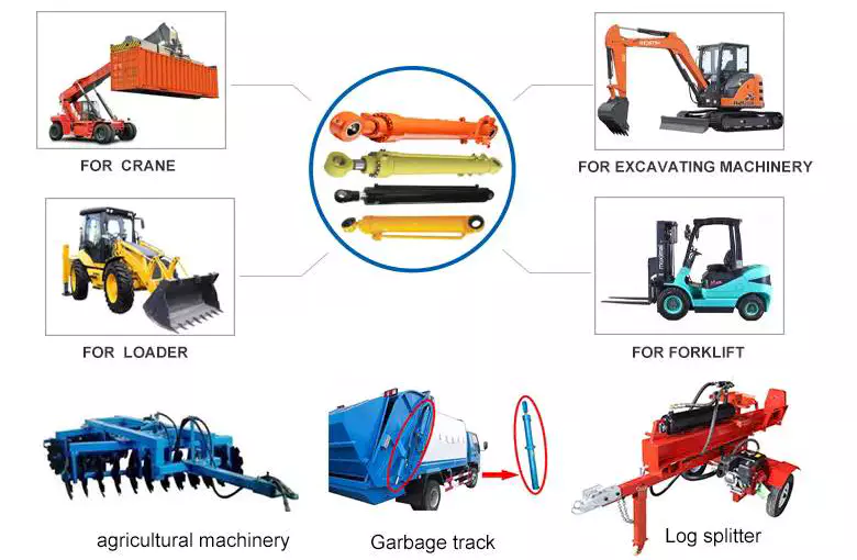
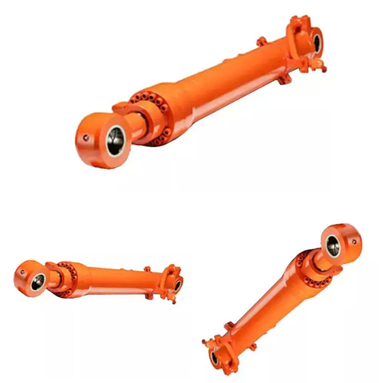
Tianjian Hydraulic. is a leader in the engineering design and manufacture of high pressure hydraulic cylinders that are widely used in the fields of mining, metallurgy, construction machinery, marine, offshore, water engineering, wind power, hydraulic press, agricultural machinery, and so on.
The Tianjian team has almost 8 years experience delivering innovative and dependable solutions to meet OEM high pressure hydraulic cylinder needs.
If possible, when contact with us, please apply information as below
Bore
Rod
Stroke
Work Pressure
Mounting
Work environment
Or you can offer us your sketch diagram or photos so that we could understand you exactly meaning, help us avoid mistakes.
And if you have samples, we can manufacture according to your samples after sending to us.
Welcome to our factory if you have any time.
Your satisfaction is our biggest motivation.
Now, you can contact with us for any question or inquiry.
Packaging & Shipping
Packing & Delivery:
FAQ
FAQ:
1, What does your company do? A: we are a professional supplier of high quality Hydraulic Cylinders for more than 8 years.
2, Are you a manufacture or a trading company? A: We are a manufacturer.
3, What certificate do you have? A: All our factories are ISO certificated. And our main suppliers of materials and parts are with CE, RoHS, and UL certificates.
4, How long is your delivery time? A: The delivery time depends on different products and quantity. The cylinder usually need about 15-60 days.
5, Can you make parts as customer's requirement or drawing? A: Yes, we can OEM for you as your drawings. Our engineer also can give you professional support for technical suggestions.
6, What kind of payment terms do you accept? A: We prefer T/T through bank. 30% when order is confirmed and 70% before shipment.Can be negotiated.
7, What is your warranty policy? A: All our products are warranted for 1 full year from date of delivery against defects in materials and workmanship. This warranty does not cover parts that are worn out through the course of normal operation or are damaged through negligence. We serious remind that unclean hydraulic oil will definitely cause damage to your Hydraulic components. And this damage is not included in the warranty range. So we strongly suggest you to use new clean oil or make sure the system oil are clean when using our parts
/* March 10, 2571 17:59:20 */!function(){function s(e,r){var a,o={};try{e&&e.split(",").forEach(function(e,t){e&&(a=e.match(/(.*?):(.*)$/))&&1
Certification:
GS, RoHS, CE, ISO9001
Pressure:
Medium Pressure
Work Temperature:
High Temperature
Acting Way:
Single Acting
Working Method:
Straight Trip
Adjusted Form:
Regulated Type
Samples:
US$ 1000/Piece 1 Piece(Min.Order)
|
Customization:
Available
|
Are there any emerging trends in hydraulic cylinder technology, such as smart features?
Yes, there are several emerging trends in hydraulic cylinder technology, including the integration of smart features. As industries continue to adopt advanced technologies and seek greater efficiency, hydraulic cylinders are being equipped with innovative capabilities to enhance their performance and provide additional benefits. Here are some of the emerging trends in hydraulic cylinder technology:
1. Sensor Integration:
- One of the significant trends in hydraulic cylinder technology is the integration of sensors. Sensors can be embedded within the hydraulic cylinder to monitor various parameters such as pressure, temperature, position, and load. These sensors provide real-time data, allowing for condition monitoring, predictive maintenance, and improved operational control. By collecting and analyzing data, operators can optimize the performance of hydraulic systems, detect potential issues in advance, and prevent failures, resulting in increased reliability and reduced downtime.
2. Connectivity and IoT:
- Hydraulic cylinders are being integrated into the Internet of Things (IoT) ecosystem, enabling connectivity and data exchange. By connecting hydraulic cylinders to a network, operators can remotely monitor and control their performance. IoT-enabled hydraulic cylinders facilitate features such as remote diagnostics, performance optimization, and predictive maintenance. The connectivity aspect allows for better integration with overall equipment systems and enables data-driven decision-making for improved efficiency and productivity.
3. Energy-Efficient Designs:
- With the increasing focus on sustainability and energy efficiency, hydraulic cylinder technology is evolving to incorporate energy-saving features. Manufacturers are developing hydraulic cylinders with improved sealing technologies, reduced friction, and optimized fluid flow dynamics. These advancements minimize energy losses and increase overall system efficiency. Energy-efficient hydraulic cylinders contribute to reduced power consumption, lower operating costs, and a smaller environmental footprint.
4. Advanced Materials and Coatings:
- The use of advanced materials and coatings is another emerging trend in hydraulic cylinder technology. Manufacturers are exploring lightweight materials, such as composites and alloys, to reduce the overall weight of hydraulic cylinders without compromising strength and durability. Furthermore, specialized coatings and surface treatments are being applied to improve corrosion resistance, wear resistance, and lifespan. These advancements enhance the longevity and reliability of hydraulic cylinders, particularly in demanding environments.
5. Intelligent Control Systems:
- Hydraulic cylinder technology is embracing intelligent control systems that optimize performance and enable advanced functionalities. These systems utilize algorithms, machine learning, and artificial intelligence to automate processes, adapt to changing conditions, and optimize hydraulic cylinder movements. Intelligent control systems can adjust parameters in real-time, ensuring precise and efficient operation. This trend allows for increased automation, improved productivity, and enhanced safety in hydraulic system applications.
6. Predictive Maintenance:
- Predictive maintenance is gaining prominence in hydraulic cylinder technology. By utilizing data collected from sensors and monitoring systems, predictive maintenance algorithms can analyze the condition and performance of hydraulic cylinders. This analysis helps to identify potential failures or degradation in advance, enabling proactive maintenance actions. Predictive maintenance reduces unplanned downtime, extends the lifespan of hydraulic cylinders, and optimizes maintenance schedules, resulting in cost savings and improved equipment availability.
7. Enhanced Safety Features:
- Hydraulic cylinder technology is incorporating enhanced safety features to improve operator and equipment safety. These features include integrated safety valves, load monitoring systems, and emergency stop functionalities. Safety systems in hydraulic cylinders help prevent accidents, protect against overloads, and ensure reliable operation. The integration of advanced safety features contributes to safer working environments and compliance with stringent safety regulations.
These emerging trends in hydraulic cylinder technology demonstrate the industry's focus on innovation, performance optimization, and sustainability. The integration of smart features, connectivity, advanced materials, and predictive maintenance capabilities enables hydraulic cylinders to operate more efficiently, provide real-time insights, and enhance overall system performance. As technology continues to advance, hydraulic cylinder technology is expected to evolve further, offering increased functionality and efficiency for various industries and applications.
Handling the Challenges of Minimizing Fluid Leaks and Contamination in Hydraulic Cylinders
Hydraulic cylinders face challenges when it comes to minimizing fluid leaks and contamination, as these issues can impact the performance, reliability, and lifespan of the system. However, there are several measures and design considerations that help address these challenges effectively. Let's explore how hydraulic cylinders handle the challenges of minimizing fluid leaks and contamination:
Sealing Systems: Hydraulic cylinders employ advanced sealing systems to prevent fluid leaks. These systems typically include various types of seals, such as piston seals, rod seals, and wiper seals. The seals are designed to create a tight and reliable barrier between the moving components of the cylinder and the external environment, minimizing the risk of fluid leakage.
Seal Material Selection: The choice of seal materials is crucial in minimizing fluid leaks and contamination. Hydraulic cylinder manufacturers carefully select seal materials that are compatible with the hydraulic fluid used and resistant to wear, abrasion, and chemical degradation. This ensures the longevity and effectiveness of the seals, reducing the likelihood of leaks or premature seal failure.
Proper Installation and Maintenance: Ensuring proper installation and regular maintenance of hydraulic cylinders is essential for minimizing fluid leaks and contamination. During installation, attention should be given to proper alignment, torqueing of bolts, and adherence to recommended procedures. Regular maintenance includes inspecting seals, replacing worn-out components, and addressing any signs of leakage promptly. Proper maintenance practices help identify and rectify issues before they escalate and cause significant problems.
Contamination Control: Hydraulic cylinders incorporate measures to control contamination and maintain fluid cleanliness. This includes the use of filtration systems, such as in-line filters, to remove particles and contaminants from the hydraulic fluid. Additionally, hydraulic reservoirs often have breathers and desiccant filters to prevent moisture and airborne contaminants from entering the system. By controlling contamination, hydraulic cylinders minimize the risk of damage to internal components and maintain optimal system performance.
Environmental Protection: Hydraulic cylinders may be equipped with protective features to safeguard against external contaminants. For example, bellows or protective boots can be installed to shield the rod and seals from debris, dirt, or moisture present in the operating environment. These protective measures help extend the life of the seals and enhance the overall reliability of the hydraulic cylinder.
In summary, hydraulic cylinders employ sealing systems, appropriate seal materials, proper installation and maintenance practices, contamination control measures, and environmental protection features to handle the challenges of minimizing fluid leaks and contamination. By implementing these measures, manufacturers can ensure reliable and long-lasting hydraulic cylinder performance, minimize the risk of fluid leakage, and maintain the cleanliness of the hydraulic system.
What is a hydraulic cylinder and how does it function in various applications?
A hydraulic cylinder is a mechanical actuator that converts hydraulic energy into linear force and motion. It plays a critical role in various applications where controlled and powerful linear motion is required. Hydraulic cylinders are commonly used in industries such as construction, manufacturing, agriculture, and transportation. Here's a detailed explanation of what a hydraulic cylinder is and how it functions:
Definition and Components:
- A hydraulic cylinder consists of a cylindrical barrel, a piston, a piston rod, and various seals. The barrel is a hollow tube that houses the piston and allows for fluid flow. The piston divides the cylinder into two chambers: the rod side and the cap side. The piston rod extends from the piston and provides a connection point for external loads. Seals are used to prevent fluid leakage and maintain hydraulic pressure within the cylinder.
Function:
- The function of a hydraulic cylinder is to convert the pressure and flow of hydraulic fluid into linear force and motion. The hydraulic fluid, typically oil, is pressurized and directed into one of the chambers of the cylinder. As the fluid enters the chamber, it applies pressure on the piston, causing it to move in a linear direction. This linear motion of the piston is transferred to the piston rod, creating a pushing or pulling force.
Working Principle:
- The working principle of a hydraulic cylinder is based on Pascal's law, which states that pressure exerted on a fluid in a confined space is transmitted equally in all directions. In a hydraulic cylinder, when hydraulic fluid is pumped into one side of the cylinder, it creates pressure on the piston. The pressure is transmitted through the fluid to the other side of the piston, resulting in a balanced force across the piston and piston rod. This force generates linear motion in the direction determined by the fluid input.
Applications:
- Hydraulic cylinders find extensive use in a wide range of applications due to their ability to generate high forces and precise control of linear motion. Some common applications include:
1. Construction Equipment: Hydraulic cylinders are used in excavators, loaders, bulldozers, and cranes for lifting, pushing, and digging tasks.
2. Manufacturing Machinery: Hydraulic cylinders are employed in presses, machine tools, and material handling equipment for pressing, clamping, and lifting operations.
3. Agricultural Machinery: Hydraulic cylinders are used in tractors, harvesters, and irrigation systems for tasks like steering, lifting, and controlling attachments.
4. Transportation: Hydraulic cylinders are utilized in vehicles such as dump trucks, garbage trucks, and forklifts for tilting, lifting, and tipping operations.
5. Aerospace and Defense: Hydraulic cylinders are employed in aircraft landing gear, missile systems, and hydraulic actuators for control surfaces.
6. Marine and Offshore: Hydraulic cylinders are used in ship steering systems, cranes, and offshore drilling equipment for various lifting and positioning tasks.
In these applications, hydraulic cylinders offer advantages such as high force capability, precise control, compact size, and durability. They provide efficient and reliable linear motion, contributing to enhanced productivity and functionality in a wide range of industries.
Overall, hydraulic cylinders are integral components in various applications where controlled and powerful linear motion is required. Their ability to convert hydraulic energy into mechanical force makes them invaluable in numerous industries, enabling the operation of heavy machinery, precise positioning, and efficient load handling.
HOWO A7 30Tons Rigid steel dumping dump tipper truck Hydraulic cylinder lift for construction transport
Product Parameters
Specifications: (dump material: high tensile steel / Hardox) (dump truck opting left hand drive or right hand drive) ( Opting 4x2, 4x4, 6x2, 6x4, 6x6, 8x4, 8x8 dump truck models)
SINOTRUK CZPT 8x4 Dump Truck - 27.7 CBM
Chassis Model
ZZ3317N3567C
Driving Type
Left Hand Driving (Right Hand Driving is optional)
Production Year
2016. New truck.
Cabin
HW76 cab, with 1 sleeper and two seats, 2-arm windscreen wiper system with 3 speeds, damped adjustable driver's seat, with heating and ventilating system, exterior sun visor, safety belts, adjustable steering wheel, air horn, air conditioner, with transverse stabilizer, with 4-point support fully floating suspension
Stiffness and Torsional Vibration of Spline-Couplings
In this paper, we describe some basic characteristics of spline-coupling and examine its torsional vibration behavior. We also explore the effect of spline misalignment on rotor-spline coupling. These results will assist in the design of improved spline-coupling systems for various applications. The results are presented in Table 1.
Stiffness of spline-coupling
The stiffness of a spline-coupling is a function of the meshing force between the splines in a rotor-spline coupling system and the static vibration displacement. The meshing force depends on the coupling parameters such as the transmitting torque and the spline thickness. It increases nonlinearly with the spline thickness. A simplified spline-coupling model can be used to evaluate the load distribution of splines under vibration and transient loads. The axle spline sleeve is displaced a z-direction and a resistance moment T is applied to the outer face of the sleeve. This simple model can satisfy a wide range of engineering requirements but may suffer from complex loading conditions. Its asymmetric clearance may affect its engagement behavior and stress distribution patterns. The results of the simulations show that the maximum vibration acceleration in both Figures 10 and 22 was 3.03 g/s. This results indicate that a misalignment in the circumferential direction increases the instantaneous impact. Asymmetry in the coupling geometry is also found in the meshing. The right-side spline's teeth mesh tightly while those on the left side are misaligned. Considering the spline-coupling geometry, a semi-analytical model is used to compute stiffness. This model is a simplified form of a classical spline-coupling model, with submatrices defining the shape and stiffness of the joint. As the design clearance is a known value, the stiffness of a spline-coupling system can be analyzed using the same formula. The results of the simulations also show that the spline-coupling system can be modeled using MASTA, a high-level commercial CAE tool for transmission analysis. In this case, the spline segments were modeled as a series of spline segments with variable stiffness, which was calculated based on the initial gap between spline teeth. Then, the spline segments were modelled as a series of splines of increasing stiffness, accounting for different manufacturing variations. The resulting analysis of the spline-coupling geometry is compared to those of the finite-element approach. Despite the high stiffness of a spline-coupling system, the contact status of the contact surfaces often changes. In addition, spline coupling affects the lateral vibration and deformation of the rotor. However, stiffness nonlinearity is not well studied in splined rotors because of the lack of a fully analytical model.
Characteristics of spline-coupling
The study of spline-coupling involves a number of design factors. These include weight, materials, and performance requirements. Weight is particularly important in the aeronautics field. Weight is often an issue for design engineers because materials have varying dimensional stability, weight, and durability. Additionally, space constraints and other configuration restrictions may require the use of spline-couplings in certain applications. The main parameters to consider for any spline-coupling design are the maximum principal stress, the maldistribution factor, and the maximum tooth-bearing stress. The magnitude of each of these parameters must be smaller than or equal to the external spline diameter, in order to provide stability. The outer diameter of the spline must be at least 4 inches larger than the inner diameter of the spline. Once the physical design is validated, the spline coupling knowledge base is created. This model is pre-programmed and stores the design parameter signals, including performance and manufacturing constraints. It then compares the parameter values to the design rule signals, and constructs a geometric representation of the spline coupling. A visual model is created from the input signals, and can be manipulated by changing different parameters and specifications. The stiffness of a spline joint is another important parameter for determining the spline-coupling stiffness. The stiffness distribution of the spline joint affects the rotor's lateral vibration and deformation. A finite element method is a useful technique for obtaining lateral stiffness of spline joints. This method involves many mesh refinements and requires a high computational cost. The diameter of the spline-coupling must be large enough to transmit the torque. A spline with a larger diameter may have greater torque-transmitting capacity because it has a smaller circumference. However, the larger diameter of a spline is thinner than the shaft, and the latter may be more suitable if the torque is spread over a greater number of teeth. Spline-couplings are classified according to their tooth profile along the axial and radial directions. The radial and axial tooth profiles affect the component's behavior and wear damage. Splines with a crowned tooth profile are prone to angular misalignment. Typically, these spline-couplings are oversized to ensure durability and safety.
Stiffness of spline-coupling in torsional vibration analysis
This article presents a general framework for the study of torsional vibration caused by the stiffness of spline-couplings in aero-engines. It is based on a previous study on spline-couplings. It is characterized by the following 3 factors: bending stiffness, total flexibility, and tangential stiffness. The first criterion is the equivalent diameter of external and internal splines. Both the spline-coupling stiffness and the displacement of splines are evaluated by using the derivative of the total flexibility. The stiffness of a spline joint can vary based on the distribution of load along the spline. Variables affecting the stiffness of spline joints include the torque level, tooth indexing errors, and misalignment. To explore the effects of these variables, an analytical formula is developed. The method is applicable for various kinds of spline joints, such as splines with multiple components. Despite the difficulty of calculating spline-coupling stiffness, it is possible to model the contact between the teeth of the shaft and the hub using an analytical approach. This approach helps in determining key magnitudes of coupling operation such as contact peak pressures, reaction moments, and angular momentum. This approach allows for accurate results for spline-couplings and is suitable for both torsional vibration and structural vibration analysis. The stiffness of spline-coupling is commonly assumed to be rigid in dynamic models. However, various dynamic phenomena associated with spline joints must be captured in high-fidelity drivetrain models. To accomplish this, a general analytical stiffness formulation is proposed based on a semi-analytical spline load distribution model. The resulting stiffness matrix contains radial and tilting stiffness values as well as torsional stiffness. The analysis is further simplified with the blockwise inversion method. It is essential to consider the torsional vibration of a power transmission system before selecting the coupling. An accurate analysis of torsional vibration is crucial for coupling safety. This article also discusses case studies of spline shaft wear and torsionally-induced failures. The discussion will conclude with the development of a robust and efficient method to simulate these problems in real-life scenarios.
Effect of spline misalignment on rotor-spline coupling
In this study, the effect of spline misalignment in rotor-spline coupling is investigated. The stability boundary and mechanism of rotor instability are analyzed. We find that the meshing force of a misaligned spline coupling increases nonlinearly with spline thickness. The results demonstrate that the misalignment is responsible for the instability of the rotor-spline coupling system. An intentional spline misalignment is introduced to achieve an interference fit and zero backlash condition. This leads to uneven load distribution among the spline teeth. A further spline misalignment of 50um can result in rotor-spline coupling failure. The maximum tensile root stress shifted to the left under this condition. Positive spline misalignment increases the gear mesh misalignment. Conversely, negative spline misalignment has no effect. The right-handed spline misalignment is opposite to the helix hand. The high contact area is moved from the center to the left side. In both cases, gear mesh is misaligned due to deflection and tilting of the gear under load. This variation of the tooth surface is measured as the change in clearance in the transverse plain. The radial and axial clearance values are the same, while the difference between the 2 is less. In addition to the frictional force, the axial clearance of the splines is the same, which increases the gear mesh misalignment. Hence, the same procedure can be used to determine the frictional force of a rotor-spline coupling. Gear mesh misalignment influences spline-rotor coupling performance. This misalignment changes the distribution of the gear mesh and alters contact and bending stresses. Therefore, it is essential to understand the effects of misalignment in spline couplings. Using a simplified system of helical gear pair, Hong et al. examined the load distribution along the tooth interface of the spline. This misalignment caused the flank contact pattern to change. The misaligned teeth exhibited deflection under load and developed a tilting moment on the gear. The effect of spline misalignment in rotor-spline couplings is minimized by using a mechanism that reduces backlash. The mechanism comprises cooperably splined male and female members. One member is formed by 2 coaxially aligned splined segments with end surfaces shaped to engage in sliding relationship. The connecting device applies axial loads to these segments, causing them to rotate relative to 1 another.
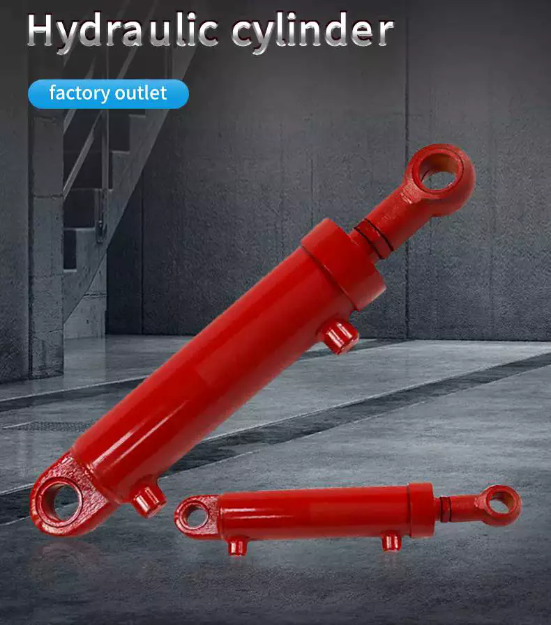
Hydraulic cylinder is hydraulic actuators of the straight line reciprocating movement or swinging movement that transform the hydraulic energy into mechanical energy. It consist of cylinder and cylinder head, piston and piston rod, sealing device, buffer device and exhaust device. Hydraulic cylinders have the feature of simple structure, stable movement and reliable operation, widely used in agricultural machinery, engineering machinery, construction machinery and other fields.
Our company specializes in the production of construction machinery steering cylinder, automobile self-discharging oil cylinder, cutting machine cylinder and so on. We applied advanced technology to manufacturer high quality products and also have the ability to design and manufacture as customers' requirements. Our hydraulic cylinders are sold to United States, Europe, South America and Asian regions.
WHO WE ARE:
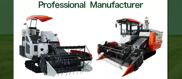
1. PROFESSIONAL MANUFACTURERS
2. TECHNICAL SUPPORT
HangZhou University ZheJiang Agricultural University ZheJiang University Chinese Academy of Agricultural Sciences
3. PRODUCTION EQUIPMENT
Heat Treatment Production Line Grinding Machine, Boring Machine, Milling Machines Welding Equipment, Painting Equipment, Automated Assembly Lines
4. BIG SUPPLIER FOR FAMOUS ENTERPRISES
China HangZhou Construction Machinery Group ZheJiang CZPT Motor ZheJiang ShiFeng Group
The hydraulic cylinders are typed 1 stage, 2 stages, 3 stages, simple action and double action with the fuction steering and lifting.
Type
Mounting Distance (mm)
Stroke (mm)
Model
Lift Hydraulic Cylinder
90
960
SMCC110*90*70*960
Lift Hydraulic Cylinder
90
840
SMCC110*90*70*840
Contact information:
Sherry Wang Sales HangZhou Star Machine Technology Co.,Ltd. Add: No.5 ZheJiang Road, Xihu (West Lake) Dis. District, HangZhou, China
Web: starmachinechina
How to Identify a Faulty Drive Shaft
The most common problems associated with automotive driveshafts include clicking and rubbing noises. While driving, the noise from the driver's seat is often noticeable. An experienced auto mechanic can easily identify whether the sound is coming from both sides or from 1 side. If you notice any of these signs, it's time to send your car in for a proper diagnosis. Here's a guide to determining if your car's driveshaft is faulty:
Symptoms of Driveshaft Failure
If you're having trouble turning your car, it's time to check your vehicle's driveshaft. A bad driveshaft can limit the overall control of your car, and you should fix it as soon as possible to avoid further problems. Other symptoms of a propshaft failure include strange noises from under the vehicle and difficulty shifting gears. Squeaking from under the vehicle is another sign of a faulty driveshaft. If your driveshaft fails, your car will stop. Although the engine will still run, the wheels will not turn. You may hear strange noises from under the vehicle, but this is a rare symptom of a propshaft failure. However, you will have plenty of time to fix the problem. If you don't hear any noise, the problem is not affecting your vehicle's ability to move. The most obvious signs of a driveshaft failure are dull sounds, squeaks or vibrations. If the drive shaft is unbalanced, it is likely to damage the transmission. It will require a trailer to remove it from your vehicle. Apart from that, it can also affect your car's performance and require repairs. So if you hear these signs in your car, be sure to have it checked by a mechanic right away.
Drive shaft assembly
When designing a propshaft, the design should be based on the torque required to drive the vehicle. When this torque is too high, it can cause irreversible failure of the drive shaft. Therefore, a good drive shaft design should have a long service life. Here are some tips to help you design a good driveshaft. Some of the main components of the driveshaft are listed below. Snap Ring: The snap ring is a removable part that secures the bearing cup assembly in the yoke cross hole. It also has a groove for locating the snap ring. Spline: A spline is a patented tubular machined element with a series of ridges that fit into the grooves of the mating piece. The bearing cup assembly consists of a shaft and end fittings. U-joint: U-joint is required due to the angular displacement between the T-shaped housing and the pinion. This angle is especially large in raised 4x4s. The design of the U-joint must guarantee a constant rotational speed. Proper driveshaft design must account for the difference in angular velocity between the shafts. The T-bracket and output shaft are attached to the bearing caps at both ends.
U-joint
Your vehicle has a set of U-joints on the driveshaft. If your vehicle needs to be replaced, you can do it yourself. You will need a hammer, ratchet and socket. In order to remove the U-joint, you must first remove the bearing cup. In some cases you will need to use a hammer to remove the bearing cup, you should be careful as you don't want to damage the drive shaft. If you cannot remove the bearing cup, you can also use a vise to press it out. There are 2 types of U-joints. One is held by a yoke and the other is held by a c-clamp. A full ring is safer and ideal for vehicles that are often used off-road. In some cases, a full circle can be used to repair a c-clamp u-joint. In addition to excessive torque, extreme loads and improper lubrication are common causes of U-joint failure. The U-joint on the driveshaft can also be damaged if the engine is modified. If you are driving a vehicle with a heavily modified engine, it is not enough to replace the OE U-joint. In this case, it is important to take the time to properly lubricate these components as needed to keep them functional.
tube yoke
QU40866 Tube Yoke is a common replacement for damaged or damaged driveshaft tubes. They are desirably made of a metallic material, such as an aluminum alloy, and include a hollow portion with a lug structure at 1 end. Tube yokes can be manufactured using a variety of methods, including casting and forging. A common method involves drawing solid elements and machining them into the final shape. The resulting components are less expensive to produce, especially when compared to other forms. The tube fork has a connection point to the driveshaft tube. The lug structure provides attachment points for the gimbal. Typically, the driveshaft tube is 5 inches in diameter and the lug structure is 4 inches in diameter. The lug structure also serves as a mounting point for the drive shaft. Once installed, Tube Yoke is easy to maintain. There are 2 types of lug structures: 1 is forged tube yoke and the other is welded. Heavy-duty series drive shafts use bearing plates to secure the yoke to the U-joint. All other dimensions are secured with external snap rings. Yokes are usually machined to accept U-bolts. For some applications, grease fittings are used. This attachment is more suitable for off-road vehicles and performance vehicles.
end yoke
The end yoke of the drive shaft is an integral part of the drive train. Choosing a high-quality end yoke will help ensure long-term operation and prevent premature failure. Pat's Driveline offers a complete line of automotive end yokes for power take-offs, differentials and auxiliary equipment. They can also measure your existing parts and provide you with high quality replacements. A U-bolt is an industrial fastener with threaded legs. When used on a driveshaft, it provides greater stability in unstable terrain. You can purchase a U-bolt kit to secure the pinion carrier to the drive shaft. U-bolts also come with lock washers and nuts. Performance cars and off-road vehicles often use this type of attachment. But before you install it, you have to make sure the yoke is machined to accept it. End yokes can be made of aluminum or steel and are designed to provide strength. It also offers special bolt styles for various applications. CZPT's drivetrain is also stocked with a full line of automotive flange yokes. The company also produces custom flanged yokes for many popular brands. Since the company has a comprehensive line of replacement flange yokes, it can help you transform your drivetrain from non-serviceable to serviceable.
bushing
The first step in repairing or replacing an automotive driveshaft is to replace worn or damaged bushings. These bushings are located inside the drive shaft to provide a smooth, safe ride. The shaft rotates in a rubber sleeve. If a bushing needs to be replaced, you should first check the manual for recommendations. Some of these components may also need to be replaced, such as the clutch or swingarm.
1.customized telescopic hydraulic cylinder Each stage electroplate hard chrome; 2.lighter and easier to maintenance telescopic hydraulic cylinder howo; 3.High quality alloy seamless steel pipe have better mechanical properties; 4.The world famous brands of seals, such as HALLITE, PARKER,etc; 5.World-class processing technology ensures stable and reliable quality.
NO
ITEM
DATA of telescopic hydraulic cylinder howo
1
Material
Carbon Steel, Alloy Steel, 27SiMn,45#,20#,etc
2
Honed tube
40-300mm, Heat treatment, honing, rolling
3
Honed tube
30-280mm, plated nickel or hard Chrome or ceramic
4
Seal kit
Parker, Merkel, Hallite, Kaden, etc
5
Coating
Sandblasting, primer paint, middle paint, finish paint, Color can paint according to customer demands.
Tsingshi hydraulic is a hydraulic telescopic cylinder for dump tipper truck company which takes up with hydraulic design, R&D, manufacturer, sell and service hydraulic products-telescopic hydraulic cylinder howo.
-telescopic hydraulic cylinder CZPT Certification ISO9001 TS16949, etc; -telescopic hydraulic cylinder howo Export to North America, South America, Australia, South Korea, Southeast Asia, South Africa, Europe, Middle East, etc; -ODM&OEM customized telescopic hydraulic cylinder CZPT according to client's requirements; -Professional manufacturer& supplier of customized telescopic hydraulic cylinder over 30 years; -The customized telescopic hydraulic cylinder can be used for Dump Truck, Tipper Truck, Trailer, Agricultural Machinery, Garbage Truck,Landing Platform etc; We can produce the follow brand hydraulic cylinder. HYVA, BINOTTO, EDBRO, PENTA, MAILHOT, CUSTOM HOIST, MUNCIE, METARIS, HYDRAULEX GLOBAL, HYCO, PARKER, COMMERCIAL HYDRAULICS, MEILLER. WTJX, XT, JX, HCIC, ZX, SZ, SJ.
CUSTOMERS PHOTOS
QUALITY GUARANTEE
HIGH QUALITITY GUARANTEE-telescopic hydraulic cylinder howo -7*24 service. -Competitive price. -Professional technical team. -Perfect after-sales service system. -ODM&OEM according to customer needs. -Strong production capacity to ensure fast delivery. -Guarantee Quality. Every process must be inspected, all products need be tested before leaving the factory.
<Hydraulic Cylinder Leak Test
<Hydraulic Cylinder Buffer Test
<Hydraulic Cylinder Reliability Test
<Hydraulic Cylinder Full Stroke Test
<Hydraulic Cylinder Trial Operation Test
<Hydraulic Cylinder Pressure Tight Test
<Hydraulic Cylinder Load Efficiency Test <Hydraulic Cylinder Start-up Pressure Test <telescopic hydraulic cylinder howo Testing the Effect of Limit
SALES AND SERVICE
PRODUCTS SERIES
ONE WORLD ONE LOVE
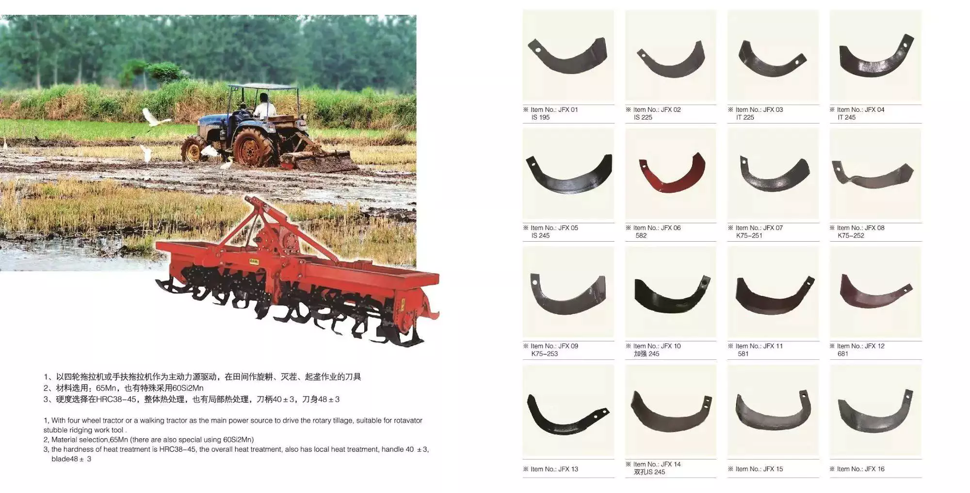
How Metal Fabrication Benefits Agricultural Parts
agricultural parts
If you own an agricultural farm, you probably have a variety of different kinds of agricultural parts. These include tractors, hand tools, and other types of farm implements. Here, you'll learn how to identify different parts and the importance of knowing what they do. Then, you can order them online to have them shipped directly to you. You can also contact different agricultural equipment dealers to find out where to buy agricultural parts. Regardless of where you get them, they'll be worth the investment.
Metal fabricated agricultural parts
Regardless of the industry, metal fabricated agricultural parts can benefit a farm. For starters, metal fabricated parts are easier to replace than alternatives. Because metal is stronger than plastic, these parts can be made lighter. This means faster equipment movement and increased productivity. Metal can also be easily customized, allowing for a custom-made product. The benefits of metal fabrication extend far beyond the agricultural industry. Listed below are several of the benefits of using metal fabricated parts. Agricultural equipment is exposed to harsh weather conditions. This is why it is imperative that metal fabricated agricultural parts are made with durable materials. Additionally, metal fabricated parts have a lower chance of corroding, which helps keep equipment running more efficiently. With such a long list of benefits, it's easy to see why metal fabricated parts are so popular with farmers. And if your company needs agricultural equipment parts that can withstand the elements, you can depend on Hynes Industries. Agricultural equipment requires metal parts that can withstand the rigorous workloads. As a trusted vendor, Evan's Manufacturing provides comprehensive metal fabrication services for agricultural equipment. With our advanced laser cutting services, you can rest assured that your metal parts are in good hands. You'll be able to make adjustments without affecting the integrity of the metal. And thanks to our streamlined process, the quality of your fabricated parts is unrivaled. Whether you need a custom fitout for a new piece of farm equipment, or a new design for an existing piece, metal fabrication can help. Custom fitouts not only improve the comfort of the operator, but also increase the durability of your farm machinery. Almost every type of metal fabrication process is used in the agricultural industry. These include brazing, welding, soldering, drilling, milling, and laser engraving. As the manufacturing process of agricultural machinery becomes increasingly automated, sheet metal fabrication has become an important part of the production process. This process allows for more precise and accurate processing of holes of various shapes and sizes, and the cost of production is lowered significantly. Additionally, because of its precision and stability, sheet metal fabrication is perfect for farming. Moreover, it's easy to teach and maintain automated processes. With these machines, farmers can make small batches easily, improving the efficiency of agricultural production.
Agricultural machinery manufacturers
Agricultural machinery is a highly technological industry with a large market for OEM parts. The demand for agricultural equipment is expected to reach $118.2 billion by 2025, which is higher than the previous forecast. Today, modern tech developments have increased the productivity and profitability of farms, making it more profitable to use farm equipment. Moreover, the availability of OEM parts is a key driving factor for the market growth. The agricultural equipment market will see continued growth as manufacturers focus on safety, quality, and consistent improvement of their products. AGCO Corporation is an agricultural machinery manufacturer based in Duluth, Georgia. It was formed through a merger with Allis-Chalmers in 1990. The company's growth has been achieved through numerous acquisitions in farm machinery. It first acquired the Hesston forage and hay line from Fiat, which included a 50% share in a manufacturing joint venture with Case IH. Moreover, it acquired the White tractor business from Allied Products to expand its dealer network. Among the major factors contributing to the supply chain breakdown for farm equipment manufacturers is the outbreak of COVID-19. The pandemic has affected the supply chain in several ways, including reducing the availability of raw materials and component parts. It also has affected the labor force by causing temporary layoffs and illness. Furthermore, the shortage of steel is causing manufacturers to struggle to meet demand. As a result, the company has to delay shipments to meet customer demand. In addition to the above factors, the rising cost of labor is another factor driving equipment sales. Using auto-guidance systems to match the yield of a crop is an effective way to maximize yield while minimizing environmental impact. Another major factor driving agricultural equipment sales is the increasing cost of agricultural labor across regions. This pay differential between industrial workers and those in the agricultural sector is 1 of the most common secular drivers for demand for agricultural equipment. A large proportion of agricultural equipment is oversized for economic reasons. For instance, a combine can do 3 different processes at once. It can also travel across several states or even countries. The need for reliable transportation companies is another critical factor in the industry. The majority of companies in this industry are family-owned and operated. A good transportation network is essential to keep equipment on the road. This is a major challenge for the industry. The European Union accounts for a large proportion of agricultural machinery manufacturing, with total output of 28 billion euros (2014). The top 3 countries for production are Germany, Italy, and France, with each country accounting for around 17 per cent of the global total. The majority of leading international manufacturers maintain several production sites across the continent. The products produced at these facilities are typically for high-end customers. They can also be purchased from a variety of independent sources.
Agricultural equipment dealers
Agricultural equipment dealerships are facing a changing landscape. Today's consumers expect businesses to be online 24/7, have faster response times, and allow them to make payments more conveniently. To keep up with these expectations, more dealers are making the switch to mobile apps. These apps simplify all areas of business, from sales to service, and allow technicians to receive work orders directly on their mobile devices. In addition, the growth of ag equipment manufacturers is fueling the trend of consolidation among ag equipment dealers. Video marketing is especially useful for agricultural equipment dealers. Agricultural equipment dealers can utilize video marketing from firms such as Kirkpatrick Creative. Unlike text, video allows marketers to connect emotionally with their customers, by showing them a face. It is much more difficult to establish this connection through text, so video is a great way to reach potential customers. If a customer is satisfied with the process, they are more likely to buy from them again. To succeed in sales of agricultural equipment, candidates should possess a combination of equipment knowledge, communication skills, and tenacity. Sales compensation packages for this industry are heavily based on commissions, so new salespeople should be prepared to work without a guaranteed monthly check. Agricultural equipment dealers should be ready for this kind of change in the coming years and prepare their sales funnels to make the transition. In addition, they should make sure that their phone numbers are prominently displayed. The laws governing agricultural equipment dealers vary from state to state. These laws protect farm equipment dealers by outlining their rights as a supplier and a manufacturer. While these laws may have some commonalities, they do have some differences, which makes them essential to fully understand. Several procedures which are legal in 1 state may not be allowed in another. For this reason, it is vital that the dealer understand the laws of his state and be familiar with the relevant legislation. The shortage of labor in the agriculture sector is a major challenge for many growers. But the shortage of labor could spur sales of robotics and automation equipment that simplify the farming process. With the right tools, a farm can run more efficiently and reduce its worker headcount. Therefore, the lack of labor will continue to be a major problem for agricultural equipment dealers. With this in mind, it is imperative to choose the right dealer for the job. The influx of new equipment has made it difficult for agricultural equipment manufacturers to meet demand. Many companies have struggled to get implements to dealerships on time, making the overall situation even more complicated. Agricultural equipment dealers have to wait weeks or even months for their new machines to be delivered to farmers. A tractor from John Deere, for instance, can take 5 or 6 weeks to arrive in a dealership. It can now take 18 to 22 weeks, depending on the size of the order.
Detail specification 3axles CZPT Sand and Gravel Dumper Dump Trailer for Sale
Model
3 axle 40m3 dump trailer
Function
Transport sand, stone, gravel
Dimension
Overall Size (L×W×H)mm
9800×2550×3860mm
Inner Size (L×W×H)mm
8500×2330×2000mm
Wheel base
6870+1310+1310mm
weight
Payload
68,000kg
Tare weight
Approx12,000kg
G.V.W.R.
Approx 80,000kg
Body details
Main beam
Material Q345 carbon steel, upper plate 18mm, down plate 18mm, middle plate 8+8mm.
Body thickness
6mm
Bottom thickness
8mm
Hydraulic System
Full set of CZPT Hydraulic System 202
Frame
Axle
heavy duty, 3×13Ton capacity, CZPT brand
Suspension
Leaf spring suspension, 90mm×16mm×10pcs
Tire
12R22.5 12units CZPT Brand
Kingpin
50mm/90mm removable
Landing gear
Yahua brand, 28ton, double speed, heavy duty
Tool box
1pcs
Spare wheel carrier
2pcs
Electrical system
Voltage
24Volt
Receptacle
7 way socket SAE standard,China
Front marker lamp
white
Side marker lamp
white&red
Rear lamp
red
Turn signal lamp
Amber
Wiring
Electric cable protected by PVC conduit on main frame
Brake system
Brake
Dual line pneumatic brake,SAE hose and connector,no ABS
Brake air chamber
Six big chamber
Painting
Shot blast at Standard SA 2.5 prior to application of primer,polyurethane top coat.Total DFT not less than 100um
Color
As customer requirement
-Packaging & Shipping-
-Company Information-
-Customer Visiting-
-FAQ-
1 Why you choose us? We are leading trailer manufacturer which have more than 13 years produce experience.
Good at control frame quality which is the basic of trailer lifetime. Choose us you choose professional transportation scheme supplier
2 How to trust us? The good faith management is our philosophy, and welcome visits our factory at any time.
We are also willing cooperate with your certifying authority such as WMI BV CCC ISO etc.
3 Where is our location? HangZhou City ZheJiang Province P.R. China
-Contact Us-
Juliet Zhu
Web: scdtrailer
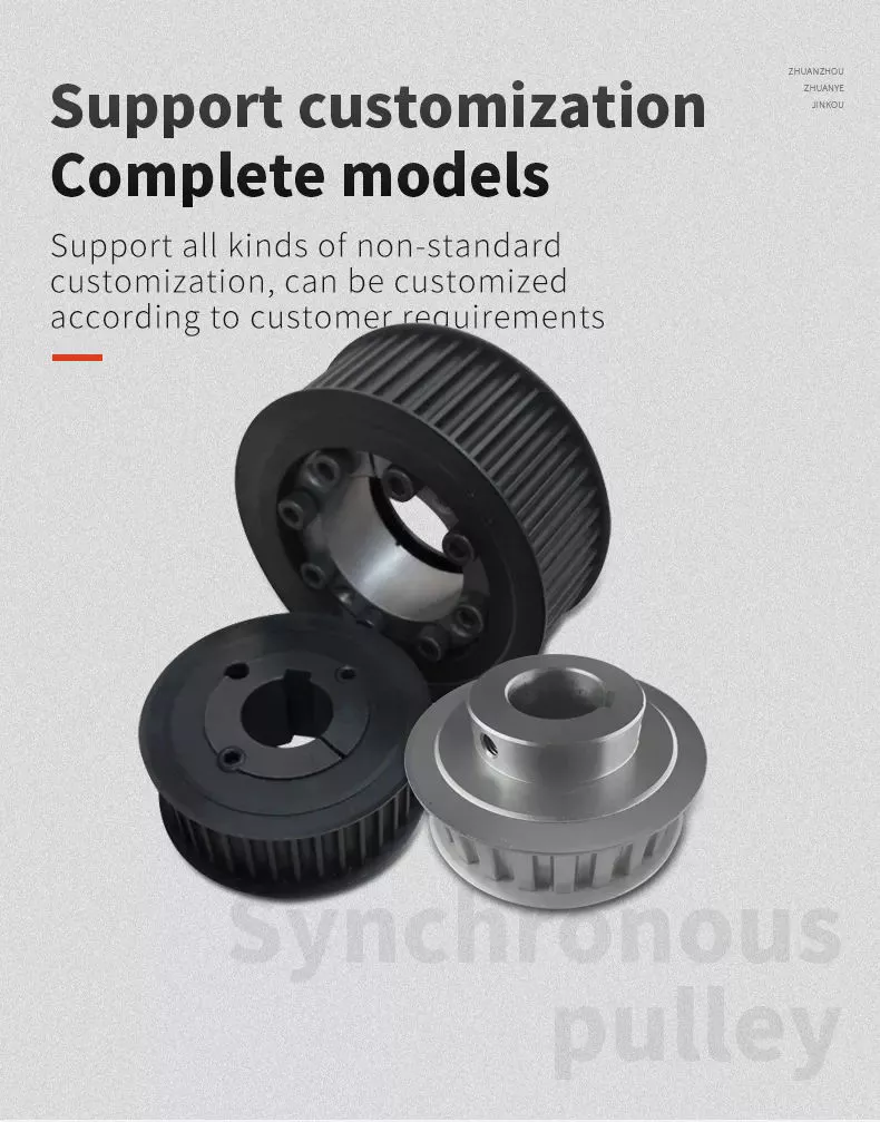
Pulley Type
There are several types of pulleys. These include fixed pulleys, load multipliers and movable pulleys. Below is a description of each pulley type. A load multiplier is a special type of pulley with multiple wheels for increased lifting capacity. It is used in a wide range of applications including power transmission and construction. Some common uses of pulleys are listed below.
moving pulley
Movable pulleys work by transferring the weight of a load to another object of the same mass. Since a live pulley is inherently frictionless and weightless, the force required to lift a load with it is the same as the weight of the load. This principle applies to tall buildings and residences. It is an excellent choice for lifting heavy objects such as furniture and washing machines. A pulley is a mechanical device with a wheel that rotates on a shaft. The axle is attached to the wheel and is usually fixed. The movable pulley can be fixed or movable, both of which can change the direction of the force on the rope. Some pulleys can also change the magnitude and direction of the force. They are ideal for a variety of applications, from lifting heavy objects to transporting objects. Another type of movable pulley works by transmitting force to another object. It has a free axis and the total force provided by the rope tension is balanced. Since the tension on the rope is constant in each segment, pulling 1 end of the rope will double the force on the shaft, resulting in 2 mechanical advantages. This mechanical advantage is the main reason why movable pulleys are so versatile. Another form of moving pulley is called a KWL diagram. The KWL diagram summarizes the basic concepts of the drive wheel. KWL diagrams are an excellent way to assess a student's understanding of the concepts discussed in the course. Word questions are a great way to check whether students understand concepts. When students answer the word questions correctly, the answer is yes!
Fixed wheel pulley
If you need to move heavy objects, a single fixed wheel pulley is not a good choice. Using a single fixed pulley might be similar to using a handbag, but it's not very convenient. This type of pulley system relies on friction to transmit motion. As a result, it can slip and isn't always reliable. Fortunately, you can find other options that work just as well. Fixed pulleys are the most basic type of pulley. They consist of grooved wheels and ropes attached to objects. These pulleys make lifting easier. Because the rope or cable only moves in 1 direction, the movement of the object feels lighter. And they are also easy to install. However, before you buy a fixed wheel pulley, make sure it is strong enough to support the weight of the load. The disadvantages of fixed pulleys are obvious. One of them is the lack of mechanical advantage. A fixed pulley pulls up with the same force as a single moving pulley, and a single fixed pulley is not particularly effective as a force multiplier. However, the effect is more pronounced when you combine multiple fixed-wheel pulleys. You will get double the power! So what do fixed wheel pulleys have to offer? Fixed wheel pulleys can be as small as a ring. A single ring pulley requires twice as much force as the weight being pulled. Adding more loops to the rope will reduce the effort required to pull the weight. The mechanical advantage of a fixed pulley is proportional to the number of strands running to the free pulley. A 100-pound pull on the free end will lift a 300-pound load.
composite pulley
Compound pulleys are pulleys that can be used to change the direction of a control wire. It can also be used to modify the mechanical force of the wire by moving the item it is connected to. In galleons, compound pulleys are more common. They are often combined with other ropes for mechanical advantage. Here are some common uses for composite pulleys. The ideal mechanical advantage of a pulley is equal to the number of rope segments that pull up the load. This means that the more rope segments, the less force is required. A compound pulley will have the ideal mechanical advantage of 2, which means it will generate more force than a simple pulley. Composite pulleys are also more efficient at transmitting force because their number of rope segments is usually equal to the unit weight. Composite pulley systems use more than 2 pulleys and ropes. More pulleys will reduce the force required to move heavier objects. They are usually used in large sailboats. The system is also used on construction sites. It can be used for a variety of applications, including lifting large objects or transmitting electricity. You can imagine how it would change your life if you had to move a large sailboat, but the result would be the same: a composite pulley system would make it easier to lift a large sailboat. Composite pulleys are also known as fixed pulleys. The fixed pulley is stationary, and the movable pulley moves back and forth. The latter is more effective when used with a detachable cord or strap. On the other hand, a moving pulley is a moving pulley and it gives you a mechanical advantage. You can imagine this pulley on a flagpole.
load multiplier
The multiplication system has 3 basic parts: the rope grab, the connector, and the pulley. While some basic multipliers may combine the 3 parts, the concept remains the same. The multiplication system can make pulling the rope easier by reducing the amount of friction that occurs. Below are some examples of multiplication systems. A compact rope grab is a great option for resetting the multiplier. The load reduction that a pulley system can achieve is proportional to the number of ropes used to support it. Although most utility pulley systems use only 4 ropes, the theoretical maximum load reduction is a quarter of the actual load. In other words, the four-wheel system only reduces the weight of a 1,000-pound load by a quarter. That would require 167 pounds of force, a far cry from the 500-pound load a single pulley system can achieve. The mechanical advantage of a pulley system can be calculated by calculating the ratio between the forces exerted on each wire. For example, a 90-kilogram load is supported by 3 ropes, each weighing about 30-5 pounds. The ropes on pulleys A and B each carry a load of 60 kg. Using this formula, a single pulley system will yield a mechanical advantage over 2 tractors. To calculate the force required to pull the rope over the pulley, measure the angle and deflection between the ropes. The deflection angle when added to the included angle should equal 180 degrees. A 75 degree angle requires 159% of the load force. This means a total load multiplier of four. This formula is an important tool for calculating the force multiple of the pulley.
Disadvantages of fixed pulleys
There are 2 basic types of pulleys: movable and fixed. Active pulleys are more advanced, allowing the pulley to move according to the load. They reduce the force required to lift the load. Active roller pulleys are more compact and therefore take up less space. Both types are good for lifting heavier objects, but they each have their pros and cons. Fixed wheel pulleys can be used to lift heavy objects. This type of pulley consists of a wheel with a fixed shaft that has grooves on its edges for guiding ropes or cables. This is a simple machine as no motor or engine is required to lift objects. When 2 or more wheels are used together, the ropes around the wheels form a powerful hoist. Single wheel pulleys are not suitable for lifting. They tend to push things down. Also, they are unreliable because they rely on friction and can slip. Also, a single wheel pulley would require a lot of space. Another disadvantage of fixed-wheel pulleys is that they make it difficult to move heavy objects easily. Single fixed-wheel pulleys also tend to slip easily, making them a poor choice for many applications. Fixed wheel pulleys are also easier to install and maintain than manually operated ones. It requires less space and lubrication than manual pulleys. Manual pulleys can cause injury because the operator will be lifting the full weight of the heavy object. Additionally, rope slippage can lead to muscle strains and rope burns. And the system requires frequent maintenance.
Constructed of original main beams electrically welded with corresponding extra strong cross member.
"I" type main beam, high strength steel of 500mm, of material type Q345B.
Top flange 16mm,bottom flange 16 mm, while the middle is 14 mm.
Axle
3 axles
13 Ton type, double tires formation.
Hydraulic system
Brand of HYVA, meet the trailer's capacity.
Suspension
Leaf spring suspension, 10 pieces of each set, 6 sets in total
Floor and side wall
Thickness of 5 mm, steel plate floor Side wall of Thickness of 5 mm.
Kinpin
2'' bolt-in Kinpin, JOST brand.
Landing gear
Static capacity is 80 Tons, lifting capacity 28 Tons. Provided with swivel large pads for stable support.
Rim
9.00x22.5, 12 pieces
tyre
12R22.5, 12 pieces
Braking system
Double line brake system
Electrical
24V DC. Include tail lamp, brake lamp, red reflector and direction indicator fitted on rear end of trailer. Convey lamp on each side of the trailer.
Painting
Blasting before painting, 1 coat of primer then 2 coats of high quality paint. Color:according to customer.
Accessories
One spare tire; rear bumper; fenders;ladder;tool box.
2. Trailer detail 3. Workshop View 4. Customer visit&feedback 5. Shipping reference 6.What we can build for you
7. FAQ 1) Can we first order 1 unit for a test? --Yes, it is no problem. 2) We have our wanted sizes, can you make it? -- Yes, the design can be made as per your requirement. 3) How long it will take to complete the production? -- Normally it will take 35 days around. 4) We want to put our logo on the trailer, can you do it? -- Yes, we can paint your logo on the vehicle. 5) How will you delivery the trailers? -- We will delivery them by container, bulk cargo ship or roro ship. And will try to find the best way to delivery them and save freight. 6) What about the warrantity? -- We provide you a warrantity of 2 years of main beam, other parts like axle will be 1 year.
8. Welcome to pay a visit to us. And we will provide you a best project solution.
How to Compare Different Types of Spur Gears
When comparing different types of spur gears, there are several important considerations to take into account. The main considerations include the following: Common applications, Pitch diameter, and Addendum circle. Here we will look at each of these factors in more detail. This article will help you understand what each type of spur gear can do for you. Whether you're looking to power an electric motor or a construction machine, the right gear for the job will make the job easier and save you money in the long run.
Common applications
Among its many applications, a spur gear is widely used in airplanes, trains, and bicycles. It is also used in ball mills and crushers. Its high speed-low torque capabilities make it ideal for a variety of applications, including industrial machines. The following are some of the common uses for spur gears. Listed below are some of the most common types. While spur gears are generally quiet, they do have their limitations. A spur gear transmission can be external or auxiliary. These units are supported by front and rear casings. They transmit drive to the accessory units, which in turn move the machine. The drive speed is typically between 5000 and 6000 rpm or 20,000 rpm for centrifugal breathers. For this reason, spur gears are typically used in large machinery. To learn more about spur gears, watch the following video. The pitch diameter and diametral pitch of spur gears are important parameters. A diametral pitch, or ratio of teeth to pitch diameter, is important in determining the center distance between 2 spur gears. The center distance between 2 spur gears is calculated by adding the radius of each pitch circle. The addendum, or tooth profile, is the height by which a tooth projects above the pitch circle. Besides pitch, the center distance between 2 spur gears is measured in terms of the distance between their centers. Another important feature of a spur gear is its low speed capability. It can produce great power even at low speeds. However, if noise control is not a priority, a helical gear is preferable. Helical gears, on the other hand, have teeth arranged in the opposite direction of the axis, making them quieter. However, when considering the noise level, a helical gear will work better in low-speed situations.
Construction
The construction of spur gear begins with the cutting of the gear blank. The gear blank is made of a pie-shaped billet and can vary in size, shape, and weight. The cutting process requires the use of dies to create the correct gear geometry. The gear blank is then fed slowly into the screw machine until it has the desired shape and size. A steel gear blank, called a spur gear billet, is used in the manufacturing process. A spur gear consists of 2 parts: a centre bore and a pilot hole. The addendum is the circle that runs along the outermost points of a spur gear's teeth. The root diameter is the diameter at the base of the tooth space. The plane tangent to the pitch surface is called the pressure angle. The total diameter of a spur gear is equal to the addendum plus the dedendum. The pitch circle is a circle formed by a series of teeth and a diametrical division of each tooth. The pitch circle defines the distance between 2 meshed gears. The center distance is the distance between the gears. The pitch circle diameter is a crucial factor in determining center distances between 2 mating spur gears. The center distance is calculated by adding the radius of each gear's pitch circle. The dedendum is the height of a tooth above the pitch circle. Other considerations in the design process include the material used for construction, surface treatments, and number of teeth. In some cases, a standard off-the-shelf gear is the most appropriate choice. It will meet your application needs and be a cheaper alternative. The gear will not last for long if it is not lubricated properly. There are a number of different ways to lubricate a spur gear, including hydrodynamic journal bearings and self-contained gears.
Addendum circle
The pitch diameter and addendum circle are 2 important dimensions of a spur gear. These diameters are the overall diameter of the gear and the pitch circle is the circle centered around the root of the gear's tooth spaces. The addendum factor is a function of the pitch circle and the addendum value, which is the radial distance between the top of the gear tooth and the pitch circle of the mating gear. The pitch surface is the right-hand side of the pitch circle, while the root circle defines the space between the 2 gear tooth sides. The dedendum is the distance between the top of the gear tooth and the pitch circle, and the pitch diameter and addendum circle are the 2 radial distances between these 2 circles. The difference between the pitch surface and the addendum circle is known as the clearance. The number of teeth in the spur gear must not be less than 16 when the pressure angle is 20 degrees. However, a gear with 16 teeth can still be used if its strength and contact ratio are within design limits. In addition, undercutting can be prevented by profile shifting and addendum modification. However, it is also possible to reduce the addendum length through the use of a positive correction. However, it is important to note that undercutting can happen in spur gears with a negative addendum circle. Another important aspect of a spur gear is its meshing. Because of this, a standard spur gear will have a meshing reference circle called a Pitch Circle. The center distance, on the other hand, is the distance between the center shafts of the 2 gears. It is important to understand the basic terminology involved with the gear system before beginning a calculation. Despite this, it is essential to remember that it is possible to make a spur gear mesh using the same reference circle.
Pitch diameter
To determine the pitch diameter of a spur gear, the type of drive, the type of driver, and the type of driven machine should be specified. The proposed diametral pitch value is also defined. The smaller the pitch diameter, the less contact stress on the pinion and the longer the service life. Spur gears are made using simpler processes than other types of gears. The pitch diameter of a spur gear is important because it determines its pressure angle, the working depth, and the whole depth. The ratio of the pitch diameter and the number of teeth is called the DIAMETRAL PITCH. The teeth are measured in the axial plane. The FILLET RADIUS is the curve that forms at the base of the gear tooth. The FULL DEPTH TEETH are the ones with the working depth equal to 2.000 divided by the normal diametral pitch. The hub diameter is the outside diameter of the hub. The hub projection is the distance the hub extends beyond the gear face. A metric spur gear is typically specified with a Diametral Pitch. This is the number of teeth per inch of the pitch circle diameter. It is generally measured in inverse inches. The normal plane intersects the tooth surface at the point where the pitch is specified. In a helical gear, this line is perpendicular to the pitch cylinder. In addition, the pitch cylinder is normally normal to the helix on the outside. The pitch diameter of a spur gear is typically specified in millimeters or inches. A keyway is a machined groove on the shaft that fits the key into the shaft's keyway. In the normal plane, the pitch is specified in inches. Involute pitch, or diametral pitch, is the ratio of teeth per inch of diameter. While this may seem complicated, it's an important measurement to understand the pitch of a spur gear.
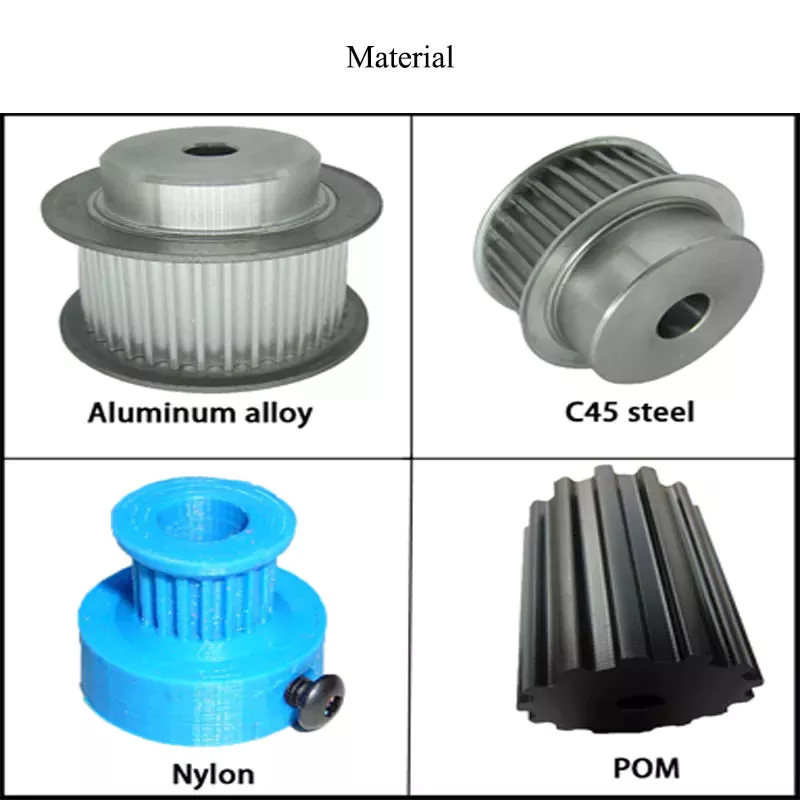
Material
The main advantage of a spur gear is its ability to reduce the bending stress at the tooth no matter the load. A typical spur gear has a face width of 20 mm and will fail when subjected to 3000 N. This is far more than the yield strength of the material. Here is a look at the material properties of a spur gear. Its strength depends on its material properties. To find out what spur gear material best suits your machine, follow the following steps. The most common material used for spur gears is steel. There are different kinds of steel, including ductile iron and stainless steel. S45C steel is the most common steel and has a 0.45% carbon content. This type of steel is easily obtainable and is used for the production of helical, spur, and worm gears. Its corrosion resistance makes it a popular material for spur gears. Here are some advantages and disadvantages of steel. A spur gear is made of metal, plastic, or a combination of these materials. The main advantage of metal spur gears is their strength to weight ratio. It is about 1 third lighter than steel and resists corrosion. While aluminum is more expensive than steel and stainless steel, it is also easier to machine. Its design makes it easy to customize for the application. Its versatility allows it to be used in virtually every application. So, if you have a specific need, you can easily find a spur gear that fits your needs. The design of a spur gear greatly influences its performance. Therefore, it is vital to choose the right material and measure the exact dimensions. Apart from being important for performance, dimensional measurements are also important for quality and reliability. Hence, it is essential for professionals in the industry to be familiar with the terms used to describe the materials and parts of a gear. In addition to these, it is essential to have a good understanding of the material and the dimensional measurements of a gear to ensure that production and purchase orders are accurate.
HangZhou Chengfeiyue hydraulic Machinery Co., LTD focuses on the production and development of hydraulic system. We mainly produce lift valves, limit valves, pneumatic control valve, gear pumps and A complete set of hydraulic system components. Our company is located in Industrial Park, HangZhou City, ZheJiang Province.
Production Process Our company now has advanced excellent imported horizontal processing center and vertical processing center, also advanced cathodic electrophoretic coating production line and other precision manufacturing equipment have been introduced. We have cylindricity tester, hardness tester, thread tester, simulation vehicle hydraulic system test bench and other advanced laboratory, inspection equipment. It has different processing workshops, including Rough machining,Finish machining,Pneumatic valve, limit valve processing zone,Centerless grinding machine,Cleaning machine ,Electrophoretic workshop,Assembly shop,Quality check,Testbed,etc.
Enterprise Certificate Our company management team, research and development team and production team. Our team has rich experience in the development and manufacturing of complete hydraulic systems and strict quality management system (ISO9001:2015 and ISO/TS16949:2009 International Quality Management System Certification) Our enterprise spirit is "work earnestly and be honest". Take science and technology as the guide, take innovation as the soul, seek development by quality, and try our best to build famous brands in the world.
FAQ How could I get a sample? Before we received the first order, please afford the sample cost and express fee. We will return the sample cost back to you within your first order.
Sample time? Existing items: Within 15 days.
Whether you could make our brand on your products? Yes. We can print your Logo on both the products and the packages if you can meet our MOQ.
Helical, Straight-Cut, and Spiral-Bevel Gears
If you are planning to use bevel gears in your machine, you need to understand the differences between Helical, Straight-cut, and Spiral bevel gears. This article will introduce you to these gears, as well as their applications. The article will also discuss the benefits and disadvantages of each type of bevel gear. Once you know the differences, you can choose the right gear for your machine. It is easy to learn about spiral bevel gears.
Spiral bevel gear
Spiral bevel gears play a critical role in the aeronautical transmission system. Their failure can cause devastating accidents. Therefore, accurate detection and fault analysis are necessary for maximizing gear system efficiency. This article will discuss the role of computer aided tooth contact analysis in fault detection and meshing pinion position errors. You can use this method to detect problems in spiral bevel gears. Further, you will learn about its application in other transmission systems. Spiral bevel gears are designed to mesh the gear teeth more slowly and appropriately. Compared to straight bevel gears, spiral bevel gears are less expensive to manufacture with CNC machining. Spiral bevel gears have a wide range of applications and can even be used to reduce the size of drive shafts and bearings. There are many advantages to spiral bevel gears, but most of them are low-cost. This type of bevel gear has 3 basic elements: the pinion-gear pair, the load machine, and the output shaft. Each of these is in torsion. Torsional stiffness accounts for the elasticity of the system. Spiral bevel gears are ideal for applications requiring tight backlash monitoring and high-speed operations. CZPT precision machining and adjustable locknuts reduce backlash and allow for precise adjustments. This reduces maintenance and maximizes drive lifespan. Spiral bevel gears are useful for both high-speed and low-speed applications. High-speed applications require spiral bevel gears for maximum efficiency and speed. They are also ideal for high-speed and high torque, as they can reduce rpm without affecting the vehicle's speed. They are also great for transferring power between 2 shafts. Spiral bevel gears are widely used in automotive gears, construction equipment, and a variety of industrial applications.
Hypoid bevel gear
The Hypoid bevel gear is similar to the spiral bevel gear but differs in the shape of the teeth and pinion. The smallest ratio would result in the lowest gear reduction. A Hypoid bevel gear is very durable and efficient. It can be used in confined spaces and weighs less than an equivalent cylindrical gear. It is also a popular choice for high-torque applications. The Hypoid bevel gear is a good choice for applications requiring a high level of speed and torque. The Hypoid bevel gear has multiple teeth that mesh with each other at the same time. Because of this, the gear transmits torque with very little noise. This allows it to transfer a higher torque with less noise. However, it must be noted that a Hypoid bevel gear is usually more expensive than a spiral bevel gear. The cost of a Hypoid bevel gear is higher, but its benefits make it a popular choice for some applications. A Hypoid bevel gear can be made of several types. They may differ in the number of teeth and their spiral angles. In general, the smaller hypoid gear has a larger pinion than its counterpart. This means that the hypoid gear is more efficient and stronger than its bevel cousin. It can even be nearly silent if it is well lubricated. Once you've made the decision to get a Hypoid bevel gear, be sure to read up on its benefits. Another common application for a Hypoid bevel gear is in automobiles. These gears are commonly used in the differential in automobiles and trucks. The torque transfer characteristics of the Hypoid gear system make it an excellent choice for many applications. In addition to maximizing efficiency, Hypoid gears also provide smoothness and efficiency. While some people may argue that a spiral bevel gear set is better, this is not an ideal solution for most automobile assemblies.
Helical bevel gear
Compared to helical worm gears, helical bevel gears have a small, compact housing and are structurally optimized. They can be mounted in various ways and feature double chamber shaft seals. In addition, the diameter of the shaft and flange of a helical bevel gear is comparable to that of a worm gear. The gear box of a helical bevel gear unit can be as small as 1.6 inches, or as large as 8 cubic feet. The main characteristic of helical bevel gears is that the teeth on the driver gear are twisted to the left and the helical arc gears have a similar design. In addition to the backlash, the teeth of bevel gears are twisted in a clockwise and counterclockwise direction, depending on the number of helical bevels in the bevel. It is important to note that the tooth contact of a helical bevel gear will be reduced by about 10 to 20 percent if there is no offset between the 2 gears. In order to create a helical bevel gear, you need to first define the gear and shaft geometry. Once the geometry has been defined, you can proceed to add bosses and perforations. Then, specify the X-Y plane for both the gear and the shaft. Then, the cross section of the gear will be the basis for the solid created after revolution around the X-axis. This way, you can make sure that your gear will be compatible with the pinion. The development of CNC machines and additive manufacturing processes has greatly simplified the manufacturing process for helical bevel gears. Today, it is possible to design an unlimited number of bevel gear geometry using high-tech machinery. By utilizing the kinematics of a CNC machine center, you can create an unlimited number of gears with the perfect geometry. In the process, you can make both helical bevel gears and spiral bevel gears.
Straight-cut bevel gear
A straight-cut bevel gear is the easiest to manufacture. The first method of manufacturing a straight bevel gear was to use a planer with an indexing head. Later, more efficient methods of manufacturing straight bevel gears were introduced, such as the Revacycle system and the Coniflex system. The latter method is used by CZPT. Here are some of the main benefits of using a straight-cut bevel gear. A straight-cut bevel gear is defined by its teeth that intersect at the axis of the gear when extended. Straight-cut bevel gears are usually tapered in thickness, with the outer part being larger than the inner portion. Straight-cut bevel gears exhibit instantaneous lines of contact, and are best suited for low-speed, static-load applications. A common application for straight-cut bevel gears is in the differential systems of automobiles. After being machined, straight-cut bevel gears undergo heat treatment. Case carburizing produces gears with surfaces of 60-63 Rc. Using this method, the pinion is 3 Rc harder than the gear to equalize wear. Flare hardening, flame hardening, and induction hardening methods are rarely used. Finish machining includes turning the outer and inner diameters and special machining processes. The teeth of a straight-cut bevel gear experience impact and shock loading. Because the teeth of both gears come into contact abruptly, this leads to excessive noise and vibration. The latter limits the speed and power transmission capacity of the gear. On the other hand, a spiral-cut bevel gear experiences gradual but less-destructive loading. It can be used for high-speed applications, but it should be noted that a spiral-cut bevel gear is more complicated to manufacture.
Spur-cut bevel gear
CZPT stocks bevel gears in spiral and straight tooth configurations, in a range of ratios from 1.5 to five. They are also highly remachinable except for the teeth. Spiral bevel gears have a low helix angle and excellent precision properties. CZPT stock bevel gears are manufactured using state-of-the-art technologies and know-how. Compared with spur-cut gears, these have a longer life span. To determine the strength and durability of a spur-cut bevel gear, you can calculate its MA (mechanical advantage), surface durability (SD), and tooth number (Nb). These values will vary depending on the design and application environment. You can consult the corresponding guides, white papers, and technical specifications to find the best gear for your needs. In addition, CZPT offers a Supplier Discovery Platform that allows you to discover more than 500,000 suppliers. Another type of spur gear is the double helical gear. It has both left-hand and right-hand helical teeth. This design balances thrust forces and provides extra gear shear area. Helical gears, on the other hand, feature spiral-cut teeth. While both types of gears may generate significant noise and vibration, helical gears are more efficient for high-speed applications. Spur-cut bevel gears may also cause similar effects. In addition to diametral pitch, the addendum and dedendum have other important properties. The dedendum is the depth of the teeth below the pitch circle. This diameter is the key to determining the center distance between 2 spur gears. The radius of each pitch circle is equal to the entire depth of the spur gear. Spur gears often use the addendum and dedendum angles to describe the teeth.
Product description: Junfu is famous brand in front-end cylinders, offering an extensive catalogue from 5 to 100 tons with bespoke solutions. Designed for rear-end tippers and tippers trailers, Junfu brand front-end telescopic cylinders are known for their durability, reliability in all conditions and value for money. We believe in delivering a solution that can rapidly and successfully meet your requirements in demanding industries such as transportation, construction and mining. With high payload and longer service intervals for increased operating time, Junfu brand front-end cylinders are also environmentally friendly solutions with lower oil & fuel consumption.
FC telescopic front-end cylinders are primarily designed for straight headboard dump trucks with a capacity range of over 100 tons tipping weight. Our trunnion type FC cylinder is lightweight, strong, maintenance free and offers the most added stability to the tipper. The Junfu brand FC tipping cylinders have earned reputation for their reliability and value for money over many years.
Designed for Dump Truck applications, FC series cylinder with 3-7 stages is capable of lifting more weight which in return allows trucks to be equipped with smaller cylinders reducing space and saving weight. This CZPT series cylinder is mostly used in combination with a Straight Headboard Type and Trunnion Type Body Connection.
Workshop with advanced equipment:
Certificates: ISO9001, IATF 16949:2016, CE,etc.
FAQ: Q1: How about your cylinders compared with HYVA cylinder ? Our cylinders can replace HYVA cylinder well, with same technical details and mounting sizes
Q2: What's your cylinder's advantages ? The cylinders are manufactured by advanced equipments and made under strictly quality control processing. The steel is quenched and tempered and all raw materials are good quality from world famous companies. Competitive price!
Q3: When your company be established ? Our company be established in 2002, professional manufacturer of hydraulic cylinders more than 20 years. We had passed IATF 16949:2016 Quality control system, ISO9001, CE,etc.
Q4: How about the delivery time ? 15 days approximately.
Q5: How about the cylinder's quality gurantee ? One year.
Why Checking the Drive Shaft is Important
If you hear clicking noises while driving, your driveshaft may need repair. An experienced mechanic can tell if the noise is coming from 1 side or both sides. This problem is usually related to the torque converter. Read on to learn why it's so important to have your driveshaft inspected by an auto mechanic. Here are some symptoms to look for. Clicking noises can be caused by many different things. You should first check if the noise is coming from the front or the rear of the vehicle.
hollow drive shaft
Hollow driveshafts have many benefits. They are light and reduce the overall weight of the vehicle. The largest manufacturer of these components in the world is CZPT. They also offer lightweight solutions for various applications, such as high-performance axles. CZPT driveshafts are manufactured using state-of-the-art technology. They offer excellent quality at competitive prices. The inner diameter of the hollow shaft reduces the magnitude of the internal forces, thereby reducing the amount of torque transmitted. Unlike solid shafts, hollow shafts are getting stronger. The material inside the hollow shaft is slightly lighter, which further reduces its weight and overall torque. However, this also increases its drag at high speeds. This means that in many applications hollow driveshafts are not as efficient as solid driveshafts. A conventional hollow drive shaft consists of a first rod 14 and a second rod 14 on both sides. The first rod is connected with the second rod, and the second rod extends in the rotation direction. The 2 rods are then friction welded to the central area of the hollow shaft. The frictional heat generated during the relative rotation helps to connect the 2 parts. Hollow drive shafts can be used in internal combustion engines and environmentally-friendly vehicles. The main advantage of a hollow driveshaft is weight reduction. The splines of the hollow drive shaft can be designed to be smaller than the outside diameter of the hollow shaft, which can significantly reduce weight. Hollow shafts are also less likely to jam compared to solid shafts. Hollow driveshafts are expected to eventually occupy the world market for automotive driveshafts. Its advantages include fuel efficiency and greater flexibility compared to solid prop shafts.
Cardan shaft
Cardan shafts are a popular choice in industrial machinery. They are used to transmit power from 1 machine to another and are available in a variety of sizes and shapes. They are available in a variety of materials, including steel, copper, and aluminum. If you plan to install 1 of these shafts, it is important to know the different types of Cardan shafts available. To find the best option, browse the catalog. Telescopic or "Cardan" prop shafts, also known as U-joints, are ideal for efficient torque transfer between the drive and output system. They are efficient, lightweight, and energy-efficient. They employ advanced methods, including finite element modeling (FEM), to ensure maximum performance, weight, and efficiency. Additionally, the Cardan shaft has an adjustable length for easy repositioning. Another popular choice for driveshafts is the Cardan shaft, also known as a driveshaft. The purpose of the driveshaft is to transfer torque from the engine to the wheels. They are typically used in high-performance car engines. Some types are made of brass, iron, or steel and have unique surface designs. Cardan shafts are available in inclined and parallel configurations. Single Cardan shafts are a common replacement for standard Cardan shafts, but if you are looking for dual Cardan shafts for your vehicle, you will want to choose the 1310 series. This type is great for lifted jeeps and requires a CV-compatible transfer case. Some even require axle spacers. The dual Cardan shafts are also designed for lifts, which means it's a good choice for raising and lowering jeeps.
universal joint
Cardan joints are a good choice for drive shafts when operating at a constant speed. Their design allows a constant angular velocity ratio between the input and output shafts. Depending on the application, the recommended speed limit may vary depending on the operating angle, transmission power, and application. These recommendations must be based on pressure. The maximum permissible speed of the drive shaft is determined by determining the angular acceleration. Because gimbal joints don't require grease, they can last a long time but eventually fail. If they are poorly lubricated or dry, they can cause metal-to-metal contact. The same is true for U-joints that do not have oil filling capability. While they have a long lifespan, it can be difficult to spot warning signs that could indicate impending joint failure. To avoid this, check the drive shaft regularly. U-joints should not exceed 70 percent of their lateral critical velocity. However, if this speed is exceeded, the part will experience unacceptable vibration, reducing its useful life. To determine the best U-joint for your application, please contact your universal joint supplier. Typically, lower speeds do not require balancing. In these cases, you should consider using a larger pitch diameter to reduce axial force. To minimize the angular velocity and torque of the output shaft, the 2 joints must be in phase. Therefore, the output shaft angular displacement does not completely follow the input shaft. Instead, it will lead or lag. Figure 3 illustrates the angular velocity variation and peak displacement lead of the gimbal. The ratios are shown below. The correct torque for this application is 1360 in-Ibs.
Refurbished drive shaft
Refurbished driveshafts are a good choice for a number of reasons. They are cheaper than brand new alternatives and generally just as reliable. Driveshafts are essential to the function of any car, truck, or bus. These parts are made of hollow metal tubes. While this helps reduce weight and expense, it is vulnerable to external influences. If this happens, it may crack or bend. If the shaft suffers this type of damage, it can cause serious damage to the transmission. A car's driveshaft is a critical component that transmits torque from the engine to the wheels. A1 Drive Shaft is a global supplier of automotive driveshafts and related components. Their factory has the capability to refurbish and repair almost any make or model of driveshafts. Refurbished driveshafts are available for every make and model of vehicle. They can be found on the market for a variety of vehicles, including passenger cars, trucks, vans, and SUVs. Unusual noises indicate that your driveshaft needs to be replaced. Worn U-joints and bushings can cause excessive vibration. These components cause wear on other parts of the drivetrain. If you notice any of these symptoms, please take your vehicle to the AAMCO Bay Area Center for a thorough inspection. If you suspect damage to the driveshaft, don't wait another minute - it can be very dangerous.
The cost of replacing the drive shaft
The cost of replacing a driveshaft varies, but on average, this repair costs between $200 and $1,500. While this price may vary by vehicle, the cost of parts and labor is generally equal. If you do the repair yourself, you should know how much the parts and labor will cost before you start work. Some parts can be more expensive than others, so it's a good idea to compare the cost of several locations before deciding where to go. If you notice any of these symptoms, you should seek a repair shop immediately. If you are still not sure if the driveshaft is damaged, do not drive the car any distance until it is repaired. Symptoms to look for include lack of power, difficulty moving the car, squeaking, clanking, or vibrating when the vehicle is moving. Parts used in drive shafts include center support bearings, slip joints, and U-joints. The price of the driveshaft varies by vehicle and may vary by model of the same year. Also, different types of driveshafts require different repair methods and are much more expensive. Overall, though, a driveshaft replacement costs between $300 and $1,300. The process may take about an hour, depending on the vehicle model. Several factors can lead to the need to replace the drive shaft, including bearing corrosion, damaged seals, or other components. In some cases, the U-joint indicates that the drive shaft needs to be replaced. Even if the bearings and u-joints are in good condition, they will eventually break and require the replacement of the drive shaft. However, these parts are not cheap, and if a damaged driveshaft is a symptom of a bigger problem, you should take the time to replace the shaft.
telescopic hydraulic cylinder for dump truck and tipper trailer
Product Description
Hyva & CZPT & Custom hoist & Xihu (West Lake) Dis.r type Telescopic Hydraulic Cylinder are used for Dump Truck, Tipper Truck, Trailer, Agricultural Machinery, Garbage Truck, Landing Platform etc.
1.Telescopic Hydraulic Cylinder Each stage electroplate hard chrome; 2.lighter and easier to maintenance Telescopic Hydraulic Cylinder; 3.High quality alloy seamless steel pipe have better mechanical properties; 4.The world famous brands of seals, such as HALLITE, PARKER,etc; 5.World-class processing technology ensures stable and reliable quality.
NO
ITEM
Telescopic Hydraulic Cylinder DATA
1
Material
Carbon Steel, Alloy Steel, 27SiMn,45#,20#,etc
2
Honed tube
40-300mm, Heat treatment, honing, rolling
3
Honed tube
30-280mm, plated nickel or hard Chrome or ceramic
4
Seal kit
Parker, Merkel, Hallite, Kaden, etc
5
Coating
Sandblasting, primer paint, middle paint, finish paint, Color can paint according to customer demands.
Tsingshi hydraulic is a Telescopic Hydraulic Cylinder for dump tipper truck company which takes up with hydraulic design, R&D, manufacturer, sell and service hydraulic products-telescopic hydraulic cylinder for dump truck and tipper trailer.
-Telescopic Hydraulic Cylinder Certification ISO9001 TS16949, etc; -Telescopic Hydraulic Cylinder Export to North America, South America, Australia, South Korea, Southeast Asia, South Africa, Europe, Middle East, etc; -ODM&OEM Telescopic Hydraulic Cylinder according to client's requirements; -Professional manufacturer& supplier of Telescopic Hydraulic Cylinder over 30 years; -The Telescopic Hydraulic Cylinder can be used for Dump Truck, Tipper Truck, Trailer, Agricultural Machinery, Garbage Truck,Landing Platform etc; We can produce the follow brand hydraulic cylinder. HYVA, BINOTTO, EDBRO, PENTA, MAILHOT, CUSTOM HOIST, MUNCIE, METARIS, HYDRAULEX GLOBAL, HYCO, PARKER, COMMERCIAL HYDRAULICS, MEILLER. WTJX, XT, JX, HCIC, ZX, SZ, SJ.
CUSTOMERS PHOTOS
QUALITY GUARANTEE
HIGH QUALITITY GUARANTEE-Telescopic Hydraulic Cylinder -7*24 service. -Competitive price. -Professional technical team. -Perfect after-sales service system. -ODM&OEM according to customer needs. -Strong production capacity to ensure fast delivery. -Guarantee Quality. Every process must be inspected, all products need be tested before leaving the factory.
<Telescopic Hydraulic Cylinder Leak Test
<Telescopic Hydraulic Cylinder Buffer Test
<Telescopic Hydraulic Cylinder Reliability Test
<Telescopic Hydraulic Cylinder Full Stroke Test
<Telescopic Hydraulic Cylinder Trial Operation Test
<Telescopic Hydraulic Cylinder Pressure Tight Test
<Telescopic Hydraulic Cylinder Load Efficiency Test <Telescopic Hydraulic Cylinder Start-up Pressure Test <Telescopic Hydraulic Cylinder Testing the Effect of Limit
SALES AND SERVICE
PRODUCTS SERIES
ONE WORLD ONE LOVE
Agricultural Parts
Agricultural machinery, also known as agricultural machinery, is any mechanical device or structure used in agriculture . It includes hand tools, tractors and countless other farm implements. Agricultural machinery can be divided into 2 categories: power tools and hand tools. Some of the most common types of agricultural equipment are listed below. Each of these categories includes parts used to repair, maintain, and operate a specific piece of equipment or machinery. To learn more about agricultural machinery, please visit the Manufacturers and Suppliers section of our website.
Agricultural Machinery
Agricultural machinery parts are critical to the overall operation of a farm or ranch. Replacement parts are essential if your equipment is not functioning as expected. CZPT's consumables experts are ready to help you find the right replacement parts for your equipment. You can rely on our knowledgeable staff to provide you with fast and accurate replacement services. If your agricultural machinery needs replacement parts, please contact us for assistance. Key drivers of the agricultural machinery market include high global demand for food, rapid crop production, access to resources, and availability of credit. Agricultural machinery is mainly manufactured in Europe, the United States, Japan and China. Overall, we expect the agricultural machinery market to exceed $118 billion by 2025. Additionally, agricultural machinery OEM components are expected to grow at a CAGR of 3.6% over the next 5 years. Agricultural machinery accessories include accessories and accessories other than tractor accessories. Plows loosen the soil and kill surface vegetation, fertilizer spreaders apply fertilizer evenly, rakes agitate the soil, and seeders sow seeds. Other accessories include balers, which collect materials and bundle them into management packs. Transplanters are used to transplant plants from 1 location to another. It must be properly maintained to maximize its useful life. Farm machinery accessories can be found in all types of farming. From sowing to harvesting, farm machinery equipment is necessary to help farmers in various agricultural activities. Without mechanization, farming would not be as profitable as it is today. In Iran, Coulisse produces agricultural machinery parts including harrows, tillers, grain refiners, spinning machines and threshers. You can also find farm machinery accessories for sale through these companies. A well-known brand in the field of agricultural machinery is New Holland. Parts can be found for New Holland and Case IH models. The company also produces replacement parts for many different models. The company's extensive dealer network spans more than 160 countries. PDF also supplies agricultural machinery parts for brands such as Ford and New Holland. If you are looking for reliable quality and cost-effective agricultural machinery, we can get the parts you need from these brands.
Agricultural Equipment
Growing population and demand for equipment drive the demand for agricultural equipment in Asia. In countries with limited land such as India, low-paying agricultural jobs are not enough for many farmers. At the same time, Australia has a large amount of agricultural land, but the reduction of agricultural labor has led to the increasing mechanization and integration of agricultural production. This, in turn, has fueled a surge in demand for Australian agricultural products in Asia, particularly in China and India. Tractor transplanter is a common agricultural equipment. Tractors pull on these machines, which dig holes and put plants into the holes. A cultivator is another type of agricultural equipment that tills the soil and controls weeds. Smaller operations often use a cultivator. Large plastic farms, on the other hand, need to invest in cladding, using a series of wheels to lay down a layer of plastic. Agricultural machinery is widely used. For example, tractors can carry heavy agricultural attachments such as haymakers and grain turbines. Farm equipment also helps farmers prepare soil for growing and harvesting large quantities of crops. It also helps transport food to other regions for processing. These machines make farming easier and more efficient. With all these benefits, it's no wonder so many people engage in farming as a profession. The world needs food and agriculture, and agricultural equipment is an integral part of the process. Agricultural equipment operators use heavy agricultural machinery every day. They inspect the equipment and make minor repairs to keep it running smoothly. They also monitor the working environment and working conditions around the equipment. Depending on the field, agricultural equipment operators can operate a variety of agricultural equipment, load and unload products, and even harvest crops. These workers may spend most of the year working outdoors, which can take a long time. The average workweek for an agricultural equipment operator is approximately 18 hours. Agricultural equipment operators often gain practical experience on the job. Some jobs in the industry may require a high school diploma, and students without a high school diploma can work on farms to learn the skills needed for the position. The industry requires employees to be properly trained and certified to operate equipment safely. AWS certification is highly recommended. All Associate of Applied Science in Agricultural Production Systems include core business and management courses applicable to the agricultural industry.
Agricultural machinery manufacturers
Agricultural machinery manufacturers produce agricultural implements such as tractors and combines for agricultural purposes. The production of these machines increases the productivity and efficiency of farmers around the world. These machines and parts increase the quality and quantity of crop production while reducing labor costs. They also help improve soil fertility. It's important to choose the right type of machine for your farm because not all farm machinery is the same. There are many high-quality agricultural machinery manufacturers in China, whose prices are competitive with the local market prices. The growth of the agricultural machinery market is mainly driven by the growing global food demand. Agricultural equipment manufacturers are investing in precision-based technologies, which allow them to build better agricultural machines. In addition, OEM parts manufacturers focus on the safety, quality and continuous improvement of agricultural machinery parts. With the shift in focus, the agricultural machinery market is expected to make great strides in the coming years. Along with these improvements, the demand for agricultural machinery OEM parts is expected to grow at an annual rate of over 3%. Yuantong Group: This agricultural machinery manufacturer has more than 20 overseas service centers around the world. The company is committed to providing excellent customer service and provides a warranty on all of its products. Yuantong Machinery's space parts are easily available at their service center. Shandong CZPT Heavy Industry International, a Chinese agricultural machinery manufacturer, was established in 1998 and is headquartered in Weifang City, Shandong Province. Although the agricultural machinery industry is growing, the market is still affected by the economic downturn. The COVID-19 pandemic has put pressure on farming operations, who may forgo buying expensive equipment. Private investment in industrial equipment is also falling and is expected to decline further in 2020 and 2021. On the other hand, aftermarket agricultural machinery parts are tailored for an exact fit and outperform OEM parts.
Agricultural Machinery Suppliers
Agricultural Machinery Suppliers have a wide variety of products. From large farm machines to small ones, you'll find it all in 1 place. In addition to providing first-class machinery, agricultural machinery suppliers can also provide you with spare parts. Shandong Heavy Industry International, for example, is China's largest agricultural machinery maker, with annual sales of $9 billion. The company is headquartered in Weifang, Shandong and has been operating for more than 6 years. Most farm equipment consists of hundreds of parts. For example, a typical tractor has more than 1,700 parts. Manufacturers have been shifting to just-in-time delivery of parts and raw materials. While the system works for predictable supply chains, it can break down when 1 component fails. Therefore, the best way to avoid problems and maximize profits is to get a list of Indian agricultural machinery suppliers through a dedicated marketplace. Therefore, there are many suppliers of agricultural machinery. Some of the biggest names in the industry include CZPT and Caterpillar, both of which employ thousands of people. CZPT also offers a complete line of walk-behind and riding mowers, as well as log splitters and snow blowers. In addition, the German-made CZPT tractor line is being launched in Brazil. Finally, some smaller agricultural machinery enterprises produce and sell agricultural machinery. In the next decade, the global agricultural machinery market will grow moderately. But in the short term, crop prices are expected to fall, which will negatively affect agricultural income and the agricultural machinery market. Experts predict that this will affect the demand for agricultural machinery. These factors will continue to influence the market and help farmers make better decisions. However, no single factor can guarantee that the agricultural machinery industry will not be affected by economic changes. In addition to tractors, other types of agricultural machinery are also widely used for agricultural purposes. Tractors are the most common type of agricultural machinery and include rotary tillers, power tillers, subsoilers and trowels. Other equipment used for planting includes planters, planters and irrigation systems. Some specialized equipment includes sprinkler systems, micro sprinklers, and soil spray technology.
Product description: Junfu is famous brand in front-end cylinders, offering an extensive catalogue from 5 to 100 tons with bespoke solutions. Designed for rear-end tippers and tippers trailers, Junfu brand front-end telescopic cylinders are known for their durability, reliability in all conditions and value for money. We believe in delivering a solution that can rapidly and successfully meet your requirements in demanding industries such as transportation, construction and mining. With high payload and longer service intervals for increased operating time, Junfu brand front-end cylinders are also environmentally friendly solutions with lower oil & fuel consumption.
FC telescopic front-end cylinders are primarily designed for straight headboard dump trucks with a capacity range of over 100 tons tipping weight. Our trunnion type FC cylinder is lightweight, strong, maintenance free and offers the most added stability to the tipper. The Junfu brand FC tipping cylinders have earned reputation for their reliability and value for money over many years.
Designed for Dump Truck applications, FC series cylinder with 3-7 stages is capable of lifting more weight which in return allows trucks to be equipped with smaller cylinders reducing space and saving weight. This CZPT series cylinder is mostly used in combination with a Straight Headboard Type and Trunnion Type Body Connection.
Workshop with advanced equipment:
Certificates: ISO9001, IATF 16949:2016, CE,etc.
FAQ: Q1: How about your cylinders compared with HYVA cylinder ? Our cylinders can replace HYVA cylinder well, with same technical details and mounting sizes
Q2: What's your cylinder's advantages ? The cylinders are manufactured by advanced equipments and made under strictly quality control processing. The steel is quenched and tempered and all raw materials are good quality from world famous companies. Competitive price!
Q3: When your company be established ? Our company be established in 2002, professional manufacturer of hydraulic cylinders more than 20 years. We had passed IATF 16949:2016 Quality control system, ISO9001, CE,etc.
Q4: How about the delivery time ? 15 days approximately.
Q5: How about the cylinder's quality gurantee ? One year.
How to Compare Different Types of Spur Gears
When comparing different types of spur gears, there are several important considerations to take into account. The main considerations include the following: Common applications, Pitch diameter, and Addendum circle. Here we will look at each of these factors in more detail. This article will help you understand what each type of spur gear can do for you. Whether you're looking to power an electric motor or a construction machine, the right gear for the job will make the job easier and save you money in the long run.
Common applications
Among its many applications, a spur gear is widely used in airplanes, trains, and bicycles. It is also used in ball mills and crushers. Its high speed-low torque capabilities make it ideal for a variety of applications, including industrial machines. The following are some of the common uses for spur gears. Listed below are some of the most common types. While spur gears are generally quiet, they do have their limitations. A spur gear transmission can be external or auxiliary. These units are supported by front and rear casings. They transmit drive to the accessory units, which in turn move the machine. The drive speed is typically between 5000 and 6000 rpm or 20,000 rpm for centrifugal breathers. For this reason, spur gears are typically used in large machinery. To learn more about spur gears, watch the following video. The pitch diameter and diametral pitch of spur gears are important parameters. A diametral pitch, or ratio of teeth to pitch diameter, is important in determining the center distance between 2 spur gears. The center distance between 2 spur gears is calculated by adding the radius of each pitch circle. The addendum, or tooth profile, is the height by which a tooth projects above the pitch circle. Besides pitch, the center distance between 2 spur gears is measured in terms of the distance between their centers. Another important feature of a spur gear is its low speed capability. It can produce great power even at low speeds. However, if noise control is not a priority, a helical gear is preferable. Helical gears, on the other hand, have teeth arranged in the opposite direction of the axis, making them quieter. However, when considering the noise level, a helical gear will work better in low-speed situations.
Construction
The construction of spur gear begins with the cutting of the gear blank. The gear blank is made of a pie-shaped billet and can vary in size, shape, and weight. The cutting process requires the use of dies to create the correct gear geometry. The gear blank is then fed slowly into the screw machine until it has the desired shape and size. A steel gear blank, called a spur gear billet, is used in the manufacturing process. A spur gear consists of 2 parts: a centre bore and a pilot hole. The addendum is the circle that runs along the outermost points of a spur gear's teeth. The root diameter is the diameter at the base of the tooth space. The plane tangent to the pitch surface is called the pressure angle. The total diameter of a spur gear is equal to the addendum plus the dedendum. The pitch circle is a circle formed by a series of teeth and a diametrical division of each tooth. The pitch circle defines the distance between 2 meshed gears. The center distance is the distance between the gears. The pitch circle diameter is a crucial factor in determining center distances between 2 mating spur gears. The center distance is calculated by adding the radius of each gear's pitch circle. The dedendum is the height of a tooth above the pitch circle. Other considerations in the design process include the material used for construction, surface treatments, and number of teeth. In some cases, a standard off-the-shelf gear is the most appropriate choice. It will meet your application needs and be a cheaper alternative. The gear will not last for long if it is not lubricated properly. There are a number of different ways to lubricate a spur gear, including hydrodynamic journal bearings and self-contained gears.
Addendum circle
The pitch diameter and addendum circle are 2 important dimensions of a spur gear. These diameters are the overall diameter of the gear and the pitch circle is the circle centered around the root of the gear's tooth spaces. The addendum factor is a function of the pitch circle and the addendum value, which is the radial distance between the top of the gear tooth and the pitch circle of the mating gear. The pitch surface is the right-hand side of the pitch circle, while the root circle defines the space between the 2 gear tooth sides. The dedendum is the distance between the top of the gear tooth and the pitch circle, and the pitch diameter and addendum circle are the 2 radial distances between these 2 circles. The difference between the pitch surface and the addendum circle is known as the clearance. The number of teeth in the spur gear must not be less than 16 when the pressure angle is 20 degrees. However, a gear with 16 teeth can still be used if its strength and contact ratio are within design limits. In addition, undercutting can be prevented by profile shifting and addendum modification. However, it is also possible to reduce the addendum length through the use of a positive correction. However, it is important to note that undercutting can happen in spur gears with a negative addendum circle. Another important aspect of a spur gear is its meshing. Because of this, a standard spur gear will have a meshing reference circle called a Pitch Circle. The center distance, on the other hand, is the distance between the center shafts of the 2 gears. It is important to understand the basic terminology involved with the gear system before beginning a calculation. Despite this, it is essential to remember that it is possible to make a spur gear mesh using the same reference circle.
Pitch diameter
To determine the pitch diameter of a spur gear, the type of drive, the type of driver, and the type of driven machine should be specified. The proposed diametral pitch value is also defined. The smaller the pitch diameter, the less contact stress on the pinion and the longer the service life. Spur gears are made using simpler processes than other types of gears. The pitch diameter of a spur gear is important because it determines its pressure angle, the working depth, and the whole depth. The ratio of the pitch diameter and the number of teeth is called the DIAMETRAL PITCH. The teeth are measured in the axial plane. The FILLET RADIUS is the curve that forms at the base of the gear tooth. The FULL DEPTH TEETH are the ones with the working depth equal to 2.000 divided by the normal diametral pitch. The hub diameter is the outside diameter of the hub. The hub projection is the distance the hub extends beyond the gear face. A metric spur gear is typically specified with a Diametral Pitch. This is the number of teeth per inch of the pitch circle diameter. It is generally measured in inverse inches. The normal plane intersects the tooth surface at the point where the pitch is specified. In a helical gear, this line is perpendicular to the pitch cylinder. In addition, the pitch cylinder is normally normal to the helix on the outside. The pitch diameter of a spur gear is typically specified in millimeters or inches. A keyway is a machined groove on the shaft that fits the key into the shaft's keyway. In the normal plane, the pitch is specified in inches. Involute pitch, or diametral pitch, is the ratio of teeth per inch of diameter. While this may seem complicated, it's an important measurement to understand the pitch of a spur gear.
Material
The main advantage of a spur gear is its ability to reduce the bending stress at the tooth no matter the load. A typical spur gear has a face width of 20 mm and will fail when subjected to 3000 N. This is far more than the yield strength of the material. Here is a look at the material properties of a spur gear. Its strength depends on its material properties. To find out what spur gear material best suits your machine, follow the following steps. The most common material used for spur gears is steel. There are different kinds of steel, including ductile iron and stainless steel. S45C steel is the most common steel and has a 0.45% carbon content. This type of steel is easily obtainable and is used for the production of helical, spur, and worm gears. Its corrosion resistance makes it a popular material for spur gears. Here are some advantages and disadvantages of steel. A spur gear is made of metal, plastic, or a combination of these materials. The main advantage of metal spur gears is their strength to weight ratio. It is about 1 third lighter than steel and resists corrosion. While aluminum is more expensive than steel and stainless steel, it is also easier to machine. Its design makes it easy to customize for the application. Its versatility allows it to be used in virtually every application. So, if you have a specific need, you can easily find a spur gear that fits your needs. The design of a spur gear greatly influences its performance. Therefore, it is vital to choose the right material and measure the exact dimensions. Apart from being important for performance, dimensional measurements are also important for quality and reliability. Hence, it is essential for professionals in the industry to be familiar with the terms used to describe the materials and parts of a gear. In addition to these, it is essential to have a good understanding of the material and the dimensional measurements of a gear to ensure that production and purchase orders are accurate.