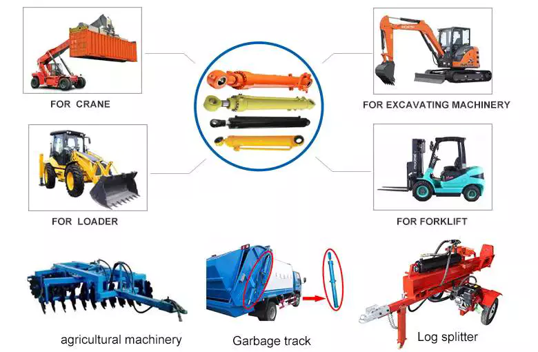
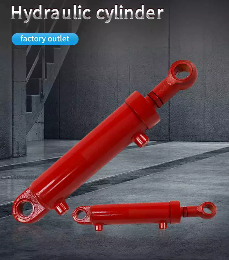
Product Description
Hydraulic Cylinder used on Front Loader
Hydraulic cylinders are an integral part of many machines and devices, and front loaders are no exception. Front loaders, also known as front end loaders or simply loaders, are heavy equipment machines used for moving, handling, and lifting materials such as dirt, sand, rocks, and other construction debris. The hydraulic cylinder in a front loader is a key component that enables the machine to perform its various functions. It is responsible for lifting the bucket and moving it into position to scoop up material. The hydraulic cylinder also allows the bucket to be lowered and dumped, releasing the material at the desired location. The combination of the hydraulic cylinder and the front loader is a force to be reckoned with. They work together seamlessly, enabling the loader to perform tasks quickly and efficiently. The hydraulic cylinder's strength and precision make it an indispensable part of the front loader, ensuring its smooth operation and reliability.
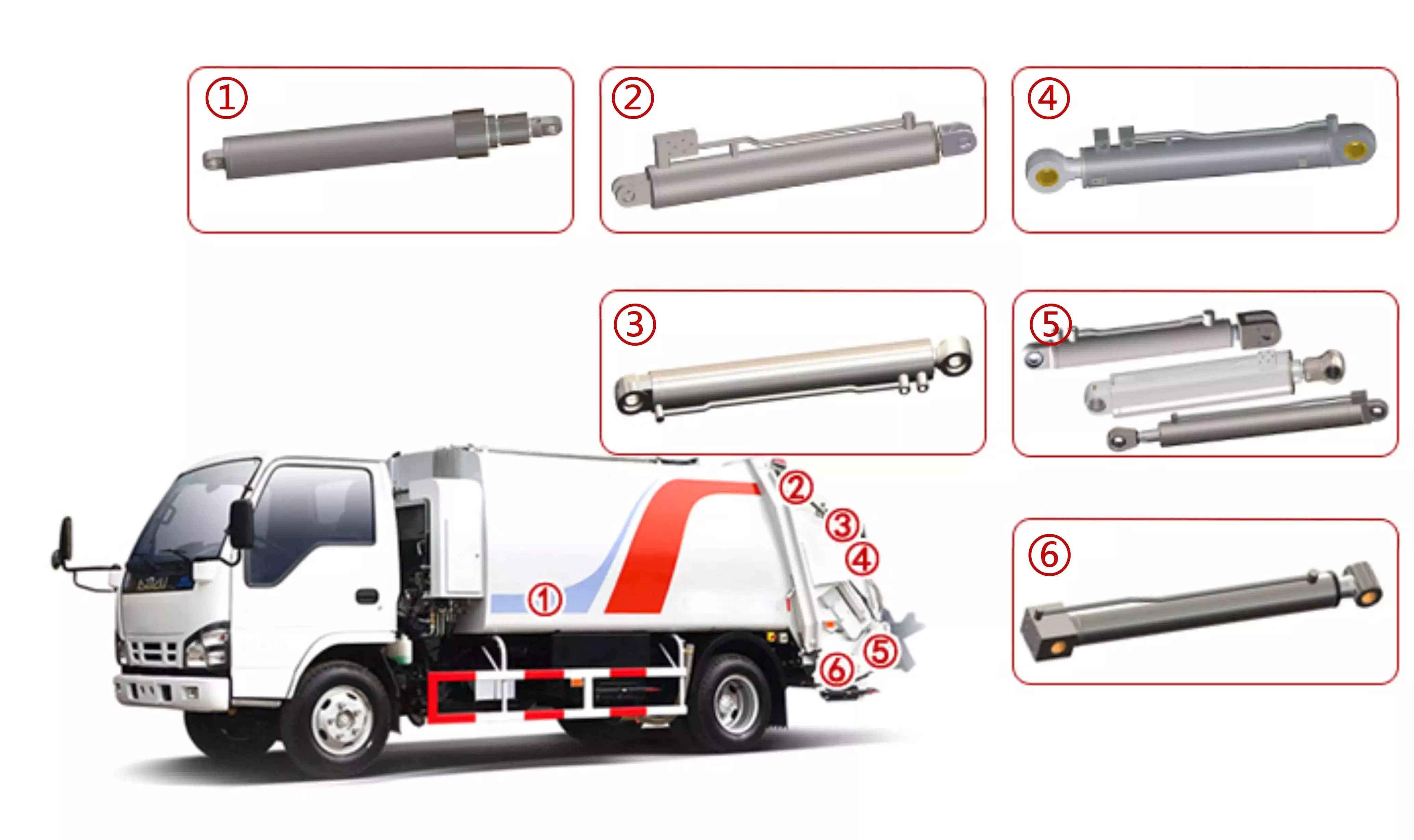
Hydraulic Cylinder used on Side Loader
The side loader garbage truck is a remarkable piece of engineering, designed with efficiency and hygiene in mind. The truck's unique design, which includes a hydraulic cylinder, allows it to handle large volumes of trash with ease. The hydraulic cylinder in a side loader is made up of 2 main parts: the cylinder tube and the piston. The cylinder tube is a hollow metal cylinder that contains the hydraulic fluid. The piston is a CHINAMFG metal rod that slides within the cylinder tube. The hydraulic cylinder is the driving force behind the side loader garbage truck's capabilities. It powers the lifting and tilting mechanisms that are essential for emptying trash containers into the truck's body. The cylinder uses pressurized hydraulic fluid to generate the force necessary to manipulate the trash container.
Hydraulic Cylinder used on Rear Loader
The rear loader garbage truck is a specialized vehicle designed to handle the collection and disposal of trash in an efficient and hygienic manner. It features a unique loading mechanism that allows trash to be emptied directly into the truck's body from the side, rather than from the rear or top.The hydraulic cylinder is what powers the trash container lifting mechanism. It uses pressurized hydraulic fluid to generate the force needed to tilt and empty the trash container into the truck's hopper. This design allows for quick and effortless emptying, reducing the time and effort needed for trash collection.The hydraulic cylinder in a rear loader must be able to withstand significant forces and pressures, as it is responsible for lifting heavy loads and repeatedly performing this task over time.
About Us
Established in 1988 , HangZhou LD Machinery Co, LTD. (hereinafter referred to "LD") is a leading manufacturer specializing in the design, research, development, manufacture and marketing in the hydraulic industry. Being one of major suppliers of customized components and cylinders for manufacturers spreaded all over the world, the company is committed to offer high quality products with competitive prices and excellent service worldwide.
Headquartered in HangZhou City, ZHangZhoug Province, the company wholly owns a subsidiary production factory named "HangZhou YUEWEI Hydraulic Technology Co., Ltd", which covers an area of more than 380,000 square meters , possesses abundant technical strength and sound production management system, superior machining production equipment, strict and effective quality control system, advanced and excellent inspection instruments.
More than 35 years experience in machining industry, with over 10 experienced technical engineers and 150 skilled workers, LD has a senior engineering technical team with special skills and rich experience in product design, casting, forging, and CNC machining, can handle special material, structure, defect and processing, meet the evolving needs, and provide optimal solution and real one-stop service to customers.
Hydraulic Cylinder Producing Process
Step1: Quality Control on Raw Material
We have our own lab in factory, inspect the raw material and do the test. For every batch of material we received, we will ask supplier provide their certificate, and then cut them to do the test again to see if the results match the certification. Also, every batch we received, we will cut them into pieces to check the air bubbles. Once they are all qualified, we will accept it, and all detail information will be recording in our ERP system. We will also pay lot of attention on the salt spray test for chrome rod. Every month, we will cut the material, put them into test machine to see if it reach the requirement. All the result will be recorded at our QC department. If customer need, we can provide it.
Step2: Quality Control on Machining
we start doing components machining from 1988 with 36 years experience now and insist doing 100% inspection. We spend lots of money, invest on auto robots and machines. Now half of the producing line is by robot so that we can ensure our quality be stable good. For every part of the cylinder, we do 3 times inspecting. Firstly, workers will do self inspection. Secondly, we have tour-hour inspection checking the products, 2 times in the morning and 2 times in the afternoon, make sure that every step is good. After the products are all completed, we will do 100% inspection. For thread, for the tolerance, everything, we need double check. Also, we have specific warehouse just for the measuring tools. Every inspector have their own measuring tool and we will check the measuring tools regularly to make sure they are all in good condition, so that the measuring results will be convincing.
Step3: Quality Control on Welding
We are qualified to AWS certification, which is very popular in North American market. First, for the visual test, we will make sure that every components are welded good, look beautiful. And the second, we need to check the penetration. We have more than 15 years experience, we do know what kind of designing angle can make the cylinder welding strong. Once we finish the first article, we will cut it and analyse the welding to see if it is fulfill the groove. And then do the radiographic testing to make sure there is no gap inside. What's more, we will do the ultrasonic test to check the program for the robot. Now 80% of welding is doing by robot. Once the program confirmed, no 1 can change it unless the welding manager, and they only have 5% right.
Step4: Quality Control on Assembling
For assembling, we have some difference with others. The brand we uses for seals are all those famous brand like Aston, Parker, Hallite. The cylinder we give to our customer has 2 years warranty. For our company, we engrave our part number and manufacturing date for the quality warranty. So no matter for seals or any others, as long as they are parts of cylinder, if it is under 2 years, we will take responsibility for them. And we will do the test for every cylinder like for pressure after we finish assembling.
Step5: Quality Control on Painting
We have our half auto painting line. Right now, we can paint about 1500 cylinders per day, which is about 1 container. Before we do the painting, we will do the wash first and for every cylinder, we will test for hardness, thickness and adhesion to make sure the painting are all good, which will be recorded into OQC report, print out and stick on the box, ship to you with your products.
Step6: Hydraulic Cylinder Packing
For every cylinder, we have the stick to show the detail information like bore size, stroke and working pressure. And we will use individual plastic bag packing. If customer need, we can also use individual carton box packing. We will fasten 1 floor after 1 floor with plat, so customer can only cut what they need and other layer will still be fasten. Moreover, there will be plywood pallet or plywood box for customer choosing. We will also send the loading picture to customer after we ship them to make sure everything is well loaded in China.
Packing Reference
Order Process
Enterprise Features
FAQ
Q1. What is LD product's quality assurance?
100% inspection for each product before shipping with inspection rereport for tracking.
Q2: How long is the warranty on LD products?
The warranty is 2 years for general products since the date of shipment.
Q3: How LD deal with the quality problem during warranty period?
1. LD will take the corresponding cost caused by customer local reparing.
2. LD will provide the product by free if the repair cost is higher than the product value, but the freight involved shall be borne by customer side.
Q4: How to ensure the order can be shipped on time?
LD will send the "production schedule" every week after receiving customers' orders. If any delays, LD will inform customers 3 weeks in advance, so as to facilitate the customer to arrange the schedule.
Q5: Does LD offer delivery service?
Yes. LD has deep cooperation with logistics companies all over the world to provide customers with quick and convenient "Door-to-Door services",including sea, air and express.
Q6: How LD control the product quality?
1. Raw materials: We will test the material of each batch of raw materials we receive, and the piston rod will be tested with salt spray. This is to ensure that the material of our products meets the requirements at the beginning.
2. Processing: We have the leading machining equipment, and obtained ISO9001 certification.
3. Welding: Our factory is equipped with welding robots, and has obtained the AWS certification.
4. Assembly pressure test: 100% testing with OQC report for cHangZhou. The seals we use are: Hallite, Aston and Gapi
/* March 10, 2571 17:59:20 */!function(){function s(e,r){var a,o={};try{e&&e.split(",").forEach(function(e,t){e&&(a=e.match(/(.*?):(.*)$/))&&1
| Certification: | ISO9001 |
|---|---|
| Pressure: | Medium Pressure |
| Work Temperature: | Normal Temperature |
| Acting Way: | Double Acting |
| Working Method: | Straight Trip |
| Adjusted Form: | Regulated Type |
| Samples: |
US$ 299/Piece
1 Piece(Min.Order) | |
|---|
| Customization: |
Available
|
|
|---|
Are there any emerging trends in hydraulic cylinder technology, such as smart features?
Yes, there are several emerging trends in hydraulic cylinder technology, including the integration of smart features. As industries continue to adopt advanced technologies and seek greater efficiency, hydraulic cylinders are being equipped with innovative capabilities to enhance their performance and provide additional benefits. Here are some of the emerging trends in hydraulic cylinder technology:
1. Sensor Integration:
- One of the significant trends in hydraulic cylinder technology is the integration of sensors. Sensors can be embedded within the hydraulic cylinder to monitor various parameters such as pressure, temperature, position, and load. These sensors provide real-time data, allowing for condition monitoring, predictive maintenance, and improved operational control. By collecting and analyzing data, operators can optimize the performance of hydraulic systems, detect potential issues in advance, and prevent failures, resulting in increased reliability and reduced downtime.
2. Connectivity and IoT:
- Hydraulic cylinders are being integrated into the Internet of Things (IoT) ecosystem, enabling connectivity and data exchange. By connecting hydraulic cylinders to a network, operators can remotely monitor and control their performance. IoT-enabled hydraulic cylinders facilitate features such as remote diagnostics, performance optimization, and predictive maintenance. The connectivity aspect allows for better integration with overall equipment systems and enables data-driven decision-making for improved efficiency and productivity.
3. Energy-Efficient Designs:
- With the increasing focus on sustainability and energy efficiency, hydraulic cylinder technology is evolving to incorporate energy-saving features. Manufacturers are developing hydraulic cylinders with improved sealing technologies, reduced friction, and optimized fluid flow dynamics. These advancements minimize energy losses and increase overall system efficiency. Energy-efficient hydraulic cylinders contribute to reduced power consumption, lower operating costs, and a smaller environmental footprint.
4. Advanced Materials and Coatings:
- The use of advanced materials and coatings is another emerging trend in hydraulic cylinder technology. Manufacturers are exploring lightweight materials, such as composites and alloys, to reduce the overall weight of hydraulic cylinders without compromising strength and durability. Furthermore, specialized coatings and surface treatments are being applied to improve corrosion resistance, wear resistance, and lifespan. These advancements enhance the longevity and reliability of hydraulic cylinders, particularly in demanding environments.
5. Intelligent Control Systems:
- Hydraulic cylinder technology is embracing intelligent control systems that optimize performance and enable advanced functionalities. These systems utilize algorithms, machine learning, and artificial intelligence to automate processes, adapt to changing conditions, and optimize hydraulic cylinder movements. Intelligent control systems can adjust parameters in real-time, ensuring precise and efficient operation. This trend allows for increased automation, improved productivity, and enhanced safety in hydraulic system applications.
6. Predictive Maintenance:
- Predictive maintenance is gaining prominence in hydraulic cylinder technology. By utilizing data collected from sensors and monitoring systems, predictive maintenance algorithms can analyze the condition and performance of hydraulic cylinders. This analysis helps to identify potential failures or degradation in advance, enabling proactive maintenance actions. Predictive maintenance reduces unplanned downtime, extends the lifespan of hydraulic cylinders, and optimizes maintenance schedules, resulting in cost savings and improved equipment availability.
7. Enhanced Safety Features:
- Hydraulic cylinder technology is incorporating enhanced safety features to improve operator and equipment safety. These features include integrated safety valves, load monitoring systems, and emergency stop functionalities. Safety systems in hydraulic cylinders help prevent accidents, protect against overloads, and ensure reliable operation. The integration of advanced safety features contributes to safer working environments and compliance with stringent safety regulations.
These emerging trends in hydraulic cylinder technology demonstrate the industry's focus on innovation, performance optimization, and sustainability. The integration of smart features, connectivity, advanced materials, and predictive maintenance capabilities enables hydraulic cylinders to operate more efficiently, provide real-time insights, and enhance overall system performance. As technology continues to advance, hydraulic cylinder technology is expected to evolve further, offering increased functionality and efficiency for various industries and applications.
Impact of Hydraulic Cylinders on Overall Productivity of Manufacturing Operations
Hydraulic cylinders play a crucial role in enhancing the overall productivity of manufacturing operations. These versatile devices are widely used in various industrial applications due to their ability to generate powerful and controlled linear motion. Let's explore how hydraulic cylinders impact the overall productivity of manufacturing operations:
- Powerful Force Generation: Hydraulic cylinders are capable of generating high forces, which enables them to handle heavy loads and perform demanding tasks. By providing the necessary force, hydraulic cylinders facilitate efficient and effective operation of machinery and equipment in manufacturing processes. This ability to exert substantial force contributes to increased productivity by enabling the handling of larger workpieces, enhancing process efficiency, and reducing manual labor requirements.
- Precision and Control: Hydraulic cylinders offer precise control over the movement of loads, allowing for accurate positioning, alignment, and repetitive tasks. The smooth and controlled linear motion provided by hydraulic cylinders ensures precise operation in manufacturing processes, such as assembly, material handling, and machining. This precision and control minimize errors, rework, and scrap, leading to improved productivity and higher-quality output.
- Speed and Efficiency: Hydraulic cylinders can operate at high speeds, enabling rapid movement and cycle times in manufacturing operations. The combination of high force and speed allows for faster operation of machinery and equipment, reducing production cycle times and increasing overall throughput. By optimizing the speed and efficiency of manufacturing processes, hydraulic cylinders contribute to improved productivity and output.
- Flexibility and Adaptability: Hydraulic cylinders are highly flexible and adaptable to different manufacturing applications. They can be customized to meet specific requirements, such as load capacity, stroke length, and mounting options. This versatility allows hydraulic cylinders to be integrated into a wide range of machinery and equipment, accommodating diverse manufacturing needs. The ability to adapt to different tasks and environments enhances overall productivity by enabling efficient utilization of resources and facilitating process optimization.
- Reliability and Durability: Hydraulic cylinders are known for their robustness and durability, making them suitable for demanding manufacturing environments. Their ability to withstand heavy loads, repeated use, and harsh operating conditions ensures reliable performance over extended periods. Minimizing downtime due to cylinder failure or maintenance requirements contributes to increased productivity and uninterrupted manufacturing operations.
In summary, hydraulic cylinders have a significant impact on the overall productivity of manufacturing operations. Their powerful force generation, precision and control, speed and efficiency, flexibility and adaptability, as well as reliability and durability, contribute to optimized processes, increased throughput, improved quality, and reduced labor requirements. By leveraging the capabilities of hydraulic cylinders, manufacturers can enhance productivity, streamline operations, and achieve greater efficiency in their manufacturing processes.
How do hydraulic cylinders accommodate variations in stroke length and force requirements?
Hydraulic cylinders are designed to accommodate variations in stroke length and force requirements, providing flexibility and adaptability for different applications. They can be tailored to meet specific needs by considering factors such as piston diameter, rod diameter, hydraulic pressure, and cylinder design. Here's a detailed explanation of how hydraulic cylinders accommodate variations in stroke length and force requirements:
1. Cylinder Size and Design:
- Hydraulic cylinders come in various sizes and designs to accommodate different stroke lengths and force requirements. The cylinder's diameter, piston area, and rod diameter are key factors that determine the force output. Larger cylinder diameters and piston areas can generate greater force, while smaller diameters are suitable for applications requiring lower force. By selecting the appropriate cylinder size and design, stroke lengths and force requirements can be effectively accommodated.
2. Piston and Rod Configurations:
- Hydraulic cylinders can be designed with different piston and rod configurations to accommodate variations in stroke length. Single-acting cylinders have a single piston and can provide a stroke in one direction. Double-acting cylinders have a piston on both sides, allowing for strokes in both directions. Telescopic cylinders consist of multiple stages that can extend and retract, providing a longer stroke length compared to standard cylinders. By selecting the appropriate piston and rod configuration, the desired stroke length can be achieved.
3. Hydraulic Pressure and Flow:
- The hydraulic pressure and flow rate supplied to the cylinder play a crucial role in accommodating variations in force requirements. Increasing the hydraulic pressure increases the force output of the cylinder, enabling it to handle higher force requirements. By adjusting the pressure and flow rate through hydraulic valves and pumps, the force output can be controlled and matched to the specific requirements of the application.
4. Customization and Tailoring:
- Hydraulic cylinders can be customized and tailored to meet specific stroke length and force requirements. Manufacturers offer a wide range of cylinder sizes, stroke lengths, and force capacities to choose from. Additionally, custom-designed cylinders can be manufactured to suit unique applications with specific stroke length and force demands. By working closely with hydraulic cylinder manufacturers, it is possible to obtain cylinders that precisely match the required stroke length and force requirements.
5. Multiple Cylinders and Synchronization:
- In applications that require high force or longer stroke lengths, multiple hydraulic cylinders can be used in combination. By synchronizing the movement of multiple cylinders through the hydraulic system, the stroke length and force output can be effectively increased. Synchronization can be achieved using mechanical linkages, electronic controls, or hydraulic circuitry, ensuring coordinated movement and force distribution across the cylinders.
6. Load-Sensing and Pressure Control:
- Hydraulic systems can incorporate load-sensing and pressure control mechanisms to accommodate variations in force requirements. Load-sensing systems monitor the load demand and adjust the hydraulic pressure accordingly, ensuring that the cylinder delivers the required force without exerting excessive force. Pressure control valves regulate the pressure within the hydraulic system, allowing for precise control and adjustment of the force output based on the application's needs.
7. Safety Considerations:
- When accommodating variations in stroke length and force requirements, it is essential to consider safety factors. Hydraulic cylinders should be selected and designed with an appropriate safety margin to handle unexpected loads or variations in operating conditions. Safety mechanisms such as overload protection valves and pressure relief valves can be incorporated to prevent damage or failure in situations where the force limits are exceeded.
By considering factors such as cylinder size and design, piston and rod configurations, hydraulic pressure and flow, customization options, synchronization, load-sensing, pressure control, and safety considerations, hydraulic cylinders can effectively accommodate variations in stroke length and force requirements. This flexibility allows hydraulic cylinders to be tailored to meet the specific demands of a wide range of applications, ensuring optimal performance and efficiency.


editor by CX 2024-01-16
China manufacturer CZPT Excavator Ex60-1 Boom Arm/Stick Bucket Hydraulic Cylinder with Free Design Custom
Product Description
Hydraulic Cylinders for Earth Moving Machinery
Machine workshop
- product view
Hydraulic cylinders that are used on construction equipment must be rugged and reliable. They will experience a lifetime exposed to heavy use in a harsh environment. Failure in service will result in costly downtime, project delays and maintenance headaches.
These cylinders must be designed to withstand the following:
Temperature Extremes -winter cold and summer heat.
Abrasives - dirt, CZPT and dust.
Corrosive Environments - rain and salt.
Work Load - heavy continual use.
Contamination - asphalt and cement splatter.
- Technology
| Hydraulic Cylinder Tube: Using imported equipment rolling machine | |||
| Kind of steel | 45# | Tensile strength N/mm | ≥647 |
| Linearity | 0.3-1/1000 | Specific elongation | ≥4 |
| Precision of size | HB | ||
| Roughness of inner hole | 0.4-0.8 | ||
| Piston rod: Adopt high precision mirror polishing | |
| Material | 45# high grade carbon steel or 40CR |
| Tempering hardness | HB240-260 |
| The depth of the high frequency | 2mm-3mm |
| High frequency hardness | HRC55°±2° |
| Chrome plating thickness | 0.03mm-0.06mm |
| Chromium layer hardness | HV800-1000vpn |
| Straightness | ≤0.08mm/m |
| Surface roughness | Ra0.03um- Ra0.06um |
| Outside diameter tolerance | f7 |
CMM INSPECTION ON SITE
- Advanced Equipment
*Skive Roller Burnishing Machines
*Vertical Honing machine
*Mchining Centers
*CNC Lathes
*Automatic Welding Machines
*Grinders
*Polishing machine
*Cylinder Assembly Benches
*Cylinder Test Benches
*Spray room
- Process flow
Materials feeling → Tempering → Cylindrical lathe cutting → High-frequency quenching → Cylindrical grinding → Hard chrome plating → External grinding
After tempering and surface high-frequency quenching,external surface hard chrome
painting, make it hard both internal and external with smooth surface.
- Service
Tooling warehouse
Customer visit:
Warehouse
- FAQ:
Q1:How about the quality?
A:Third party inspections are always welcomed. Like BV, SGS etc.
Q2: How long is the delivery time?
A: Generally about 5-10 days if the goods in stock. Or will be 15-20 days if the goods are not in stock. And also according to the quantity.
Q3:May I customize the steel pipe?
A:Sure you can, we can produce according to your requirement, you can send the CAD or design drawing.
Q4:Any value-added Services?
A: Fortunately for you,we are very experience in this industry. We have equipped our warehouse with the necessities to perform in-house painting,coating,pipe cutting, etc.
Q5: How about the trade terms?
A: EXW, FOB, CFR, CIF, LC will be accepted.
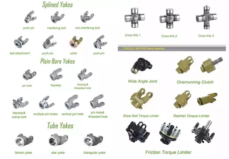
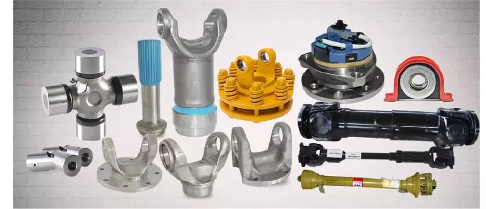
Drive shaft type
The driveshaft transfers torque from the engine to the wheels and is responsible for the smooth running of the vehicle. Its design had to compensate for differences in length and angle. It must also ensure perfect synchronization between its joints. The drive shaft should be made of high-grade materials to achieve the best balance of stiffness and elasticity. There are 3 main types of drive shafts. These include: end yokes, tube yokes and tapered shafts.
tube yoke
Tube yokes are shaft assemblies that use metallic materials as the main structural component. The yoke includes a uniform, substantially uniform wall thickness, a first end and an axially extending second end. The first diameter of the drive shaft is greater than the second diameter, and the yoke further includes a pair of opposing lugs extending from the second end. These lugs have holes at the ends for attaching the axle to the vehicle.
By retrofitting the driveshaft tube end into a tube fork with seat. This valve seat transmits torque to the driveshaft tube. The fillet weld 28 enhances the torque transfer capability of the tube yoke. The yoke is usually made of aluminum alloy or metal material. It is also used to connect the drive shaft to the yoke. Various designs are possible.
The QU40866 tube yoke is used with an external snap ring type universal joint. It has a cup diameter of 1-3/16" and an overall width of 4½". U-bolt kits are another option. It has threaded legs and locks to help secure the yoke to the drive shaft. Some performance cars and off-road vehicles use U-bolts. Yokes must be machined to accept U-bolts, and U-bolt kits are often the preferred accessory.
The end yoke is the mechanical part that connects the drive shaft to the stub shaft. These yokes are usually designed for specific drivetrain components and can be customized to your needs. Pat's drivetrain offers OEM replacement and custom flanged yokes.
If your tractor uses PTO components, the cross and bearing kit is the perfect tool to make the connection. Additionally, cross and bearing kits help you match the correct yoke to the shaft. When choosing a yoke, be sure to measure the outside diameter of the U-joint cap and the inside diameter of the yoke ears. After taking the measurements, consult the cross and bearing identification drawings to make sure they match.
While tube yokes are usually easy to replace, the best results come from a qualified machine shop. Dedicated driveshaft specialists can assemble and balance finished driveshafts. If you are unsure of a particular aspect, please refer to the TM3000 Driveshaft and Cardan Joint Service Manual for more information. You can also consult an excerpt from the TSB3510 manual for information on angle, vibration and runout.
The sliding fork is another important part of the drive shaft. It can bend over rough terrain, allowing the U-joint to keep spinning in tougher conditions. If the slip yoke fails, you will not be able to drive and will clang. You need to replace it as soon as possible to avoid any dangerous driving conditions. So if you notice any dings, be sure to check the yoke.
If you detect any vibrations, the drivetrain may need adjustment. It's a simple process. First, rotate the driveshaft until you find the correct alignment between the tube yoke and the sliding yoke of the rear differential. If there is no noticeable vibration, you can wait for a while to resolve the problem. Keep in mind that it may be convenient to postpone repairs temporarily, but it may cause bigger problems later.
end yoke
If your driveshaft requires a new end yoke, CZPT has several drivetrain options. Our automotive end yoke inventory includes keyed and non-keyed options. If you need tapered or straight holes, we can also make them for you.
A U-bolt is an industrial fastener that has U-shaped threads on its legs. They are often used to join 2 heads back to back. These are convenient options to help keep drivetrain components in place when driving over rough terrain, and are generally compatible with a variety of models. U-bolts require a specially machined yoke to accept them, so be sure to order the correct size.
The sliding fork helps transfer power from the transfer case to the driveshaft. They slide in and out of the transfer case, allowing the u-joint to rotate. Sliding yokes or "slips" can be purchased separately. Whether you need a new 1 or just a few components to upgrade your driveshaft, 4 CZPT Parts will have the parts you need to repair your vehicle.
The end yoke is a necessary part of the drive shaft. It connects the drive train and the mating flange. They are also used in auxiliary power equipment. CZPT's drivetrains are stocked with a variety of flanged yokes for OEM applications and custom builds. You can also find flanged yokes for constant velocity joints in our extensive inventory. If you don't want to modify your existing drivetrain, we can even make a custom yoke for you.


China Custom CZPT A7 30tons Rigid Steel Dumping Dump Tipper Truck Hydraulic Cylinder Lift for Construction Transport with Free Design Custom
Product Description
HOWO A7 30Tons Rigid steel dumping dump tipper truck Hydraulic cylinder lift for construction transport
Product Parameters
Specifications:
(dump material: high tensile steel / Hardox)
(dump truck opting left hand drive or right hand drive)
( Opting 4x2, 4x4, 6x2, 6x4, 6x6, 8x4, 8x8 dump truck models)
| SINOTRUK CZPT 8x4 Dump Truck - 27.7 CBM | |||||||||||||||||||||||||||||||||||||||||||||||||||||||||||||||||||||||||||||||||||||||||||||||||||||||||||||||||||||||||||||||||||||||||||||||||||||||||||||||||||||||||||||||||||||||||||||||||||||||||||||||||||||||||||||||||||||||||||||||||||||||||||||||||||||||||||||||||||||||||||||||||||||||||||||||||||||||||||||||||||||||||||
| Chassis Model | ZZ3317N3567C | ||||||||||||||||||||||||||||||||||||||||||||||||||||||||||||||||||||||||||||||||||||||||||||||||||||||||||||||||||||||||||||||||||||||||||||||||||||||||||||||||||||||||||||||||||||||||||||||||||||||||||||||||||||||||||||||||||||||||||||||||||||||||||||||||||||||||||||||||||||||||||||||||||||||||||||||||||||||||||||||||||||||||||
| Driving Type | Left Hand Driving (Right Hand Driving is optional) | ||||||||||||||||||||||||||||||||||||||||||||||||||||||||||||||||||||||||||||||||||||||||||||||||||||||||||||||||||||||||||||||||||||||||||||||||||||||||||||||||||||||||||||||||||||||||||||||||||||||||||||||||||||||||||||||||||||||||||||||||||||||||||||||||||||||||||||||||||||||||||||||||||||||||||||||||||||||||||||||||||||||||||
| Production Year | 2016. New truck. | ||||||||||||||||||||||||||||||||||||||||||||||||||||||||||||||||||||||||||||||||||||||||||||||||||||||||||||||||||||||||||||||||||||||||||||||||||||||||||||||||||||||||||||||||||||||||||||||||||||||||||||||||||||||||||||||||||||||||||||||||||||||||||||||||||||||||||||||||||||||||||||||||||||||||||||||||||||||||||||||||||||||||||
| Cabin | HW76 cab, with 1 sleeper and two seats, 2-arm windscreen wiper system with 3 speeds, damped adjustable driver's seat, with heating and ventilating system, exterior sun visor, safety belts, adjustable steering wheel, air horn, air conditioner, with transverse stabilizer, with 4-point support fully floating suspension
Stiffness and Torsional Vibration of Spline-CouplingsIn this paper, we describe some basic characteristics of spline-coupling and examine its torsional vibration behavior. We also explore the effect of spline misalignment on rotor-spline coupling. These results will assist in the design of improved spline-coupling systems for various applications. The results are presented in Table 1. Stiffness of spline-couplingThe stiffness of a spline-coupling is a function of the meshing force between the splines in a rotor-spline coupling system and the static vibration displacement. The meshing force depends on the coupling parameters such as the transmitting torque and the spline thickness. It increases nonlinearly with the spline thickness. Characteristics of spline-couplingThe study of spline-coupling involves a number of design factors. These include weight, materials, and performance requirements. Weight is particularly important in the aeronautics field. Weight is often an issue for design engineers because materials have varying dimensional stability, weight, and durability. Additionally, space constraints and other configuration restrictions may require the use of spline-couplings in certain applications. Stiffness of spline-coupling in torsional vibration analysisThis article presents a general framework for the study of torsional vibration caused by the stiffness of spline-couplings in aero-engines. It is based on a previous study on spline-couplings. It is characterized by the following 3 factors: bending stiffness, total flexibility, and tangential stiffness. The first criterion is the equivalent diameter of external and internal splines. Both the spline-coupling stiffness and the displacement of splines are evaluated by using the derivative of the total flexibility. Effect of spline misalignment on rotor-spline couplingIn this study, the effect of spline misalignment in rotor-spline coupling is investigated. The stability boundary and mechanism of rotor instability are analyzed. We find that the meshing force of a misaligned spline coupling increases nonlinearly with spline thickness. The results demonstrate that the misalignment is responsible for the instability of the rotor-spline coupling system.
China Standard Hydraulic Cylinder 1444742 for Daf Xf95 Xf105 with Free Design Custom
Product Description
DAF Hydraulic Cylinder 1349831 1295723 372863 134 0 1444742 1. For MERCEDES: Actros, Axor, Atego, SK, NG , Econic 2. For VOLVO: FH, FH12, FH16, FM9, FM12, FL 3. For SCANIA: P/G/R/T, 4 series, 3 series
4. For MAN: TGX, TGS, TGL, TGM, TGA, F2000
5. For RENAULT: Premium, Magnum, Midlum, Kerax 6. For DAF: XF105, XF95, XF85, CF65, LF55, LF45 7. For IVECO: Stralis, Eurocargo, Eurotech, Eurostar
An Overview of Worm Shafts and GearsThis article provides an overview of worm shafts and gears, including the type of toothing and deflection they experience. Other topics covered include the use of aluminum versus bronze worm shafts, calculating worm shaft deflection and lubrication. A thorough understanding of these issues will help you to design better gearboxes and other worm gear mechanisms. For further information, please visit the related websites. We also hope that you will find this article informative. Double throat worm gearsThe pitch diameter of a worm and the pitch of its worm wheel must be equal. The 2 types of worm gears have the same pitch diameter, but the difference lies in their axial and circular pitches. The pitch diameter is the distance between the worm's teeth along its axis and the pitch diameter of the larger gear. Worms are made with left-handed or right-handed threads. The lead of the worm is the distance a point on the thread travels during 1 revolution of the worm gear. The backlash measurement should be made in a few different places on the gear wheel, as a large amount of backlash implies tooth spacing. Bronze or aluminum worm shaftsWhen selecting a worm, a few things should be kept in mind. The material of the shaft should be either bronze or aluminum. The worm itself is the primary component, but there are also addendum gears that are available. The total number of teeth on both the worm and the addendum gear should be greater than 40. The axial pitch of the worm needs to match the circular pitch of the larger gear. Calculation of worm shaft deflectionThe centre-line distance of a worm gear and the number of worm teeth play a crucial role in the deflection of the rotor. These parameters should be entered into the tool in the same units as the main calculation. The selected variant is then transferred to the main calculation. The deflection of the worm gear can be calculated from the angle at which the worm teeth shrink. The following calculation is helpful for designing a worm gear. Lubrication of worm shaftsIn order to protect the gears, worm drives require lubricants that offer excellent anti-wear protection, high oxidation resistance, and low friction. While mineral oil lubricants are widely used, synthetic base oils have better performance characteristics and lower operating temperatures. The Arrhenius Rate Rule states that chemical reactions double every 10 degrees C. Synthetic lubricants are the best choice for these applications.
China factory Helac Hydraulic Rotary Actuators Cylinder L10 L20 L30 T20 T30 Rack and Pinion Swing Cylinder High Torque Rotary L20-4.5 8.2 15 25 39 with Free Design Custom
Product Description
HBOETH's innovative sliding-spline technology converts
| ||||||||||||||||||||||||||||||||||||||||||||||||||||||||||||||||||||||||||||||||||||||||||||||||||||||||||||||||||||||||||||||||||||||||||||||||||||||||||||||||||||||||||||||||||||||||||||||||||||||||||||||||||||||||||||||||||||||||||||||||||||||||||||||||||||||||||||||||||||||||||||||||||||||||||||||||||||||||||||||||||||||||||


|
Product Name |
HSG Series Hydraulic Cylinder |
|||
|
Work Press |
7/14/16/21/31.5MPa 37.5/63MPa Can be Customized |
|||
|
Material |
Aluminum,Cast Iron,45mnb Steel,Stainless Steel |
|||
|
Bore Size |
40mm--320mm,Customizable |
|||
|
Shaft Diameter |
20mm--220mm,Customizable |
|||
|
Stroke Length |
30mm--14100mm,Customizable |
|||
|
Rod Surface Hardness |
HRC48-54 |
|||
|
Paint Color |
Black,Yellow,Blue,Brown,Customizable |
|||
|
Mounting |
Earring,Flange,Clevis.Foot,Trunnion,Customizable |
|||
|
Warrenty |
1 Year |
|||
|
MOQ |
1 Piece |
|||
|
Delivery Time |
7-15 Days,Also depands on specific demands |
|||
|
Certification |
ISO9001,CE |
|||
Company Profile
QIANGLIN HYDRAULIC MACHINERY CO., LTD
| QiangLin is a professional hydraulic equipment manufacturer, mainly engaged in hydraulic system design, manufacture, installation, transformation, sales, and technical services. Our manufacturing facilities are certified to the ISO 9001 standard. We are an approved supplier to many equipment manufacturers in China. We are also partners with many customers from America, Canada, Australia, Germany, England, and other European Countries. Product quality, shorter delivery time, and customer satisfaction are our long-term commitments to our worldwide customers. Hope to be your partner. |
FAQ:
Q1: Are you a trading company or a manufacturer?
A: We have our own factory.
Q2: Are you CZPT to make Non-standard or customized products?
A: Yes, we can.
Q3: How long is your delivery time?
A: Normally, the delivery time is 7 days if we have stock, 15-30 working days if we don't. but it
also depends on the product
requirements and quantity.
Q4: Do you provide samples? are the samples free or not?
A: Yes, we can provide samples, but they are not free of charge.
Q5: What are your payment terms?
A: 30% deposit T/T or Irrevocable L/C at sight, If you have any questions, please feel free to
contact us.
Q6: What are your After-sales services?
A: Before shipment, Each individual product will be strictly inspected on our factory QC Process
System. In addition, We have a
Customer Service team to respond to customers' questions within 12 hours. Being helpful in
solving customers' problems is always our goal.
Types of pulleys and their advantages and disadvantages
There are several types of pulleys. Learn the basic equations of the pulley system. Then learn about the different uses for pulleys. The disadvantages of using pulleys will be covered. Knowing these, you can buy the pulley that suits your needs. Here are some of the best pulley types and their pros and cons.
Basic equations of pulley systems
A pulley system is a mechanism that allows 2 blocks of a certain mass to be connected by a taut rope. The acceleration of each block is the same in magnitude and direction. The external force acting on each block is the weight of the block (10g) and the tension in the string. The tension between the 2 blocks is the total tension and the force acting on the pulley is the weight of the 2 blocks.
This simple mechanism uses 2 simple equations to explain how the system works. First, the mass of the weight on both sides of the pulley must be the same. When the weight is forced to move, the rope tightens and the second pulley descends. The weight is also attached to the second pulley and must be the same distance as the first pulley. This will result in a speed ratio of 2 times the distance covered by the first pulley.
Second, we have to calculate the force required to lift the object. The lower mass is supported by a wire configuration passing through all pulleys, while the uppermost pulley is used to apply the force. The lower block is used to support the weight. The applied force needs to travel a distance nx to move the weight. This distance, called MA, can be written as:
Once we have gathered the necessary information, we can apply the calculations to the pulley system. We can also use the Mechanical Advantage Calculator to calculate the force on the anchor. To do this, we must apply a force to the load as well as to the pulley itself. Using this equation, we can calculate the force required by the load to lift the load.
Types of pulleys
There are 3 basic types of pulleys: movable, fixed and compound. Both types of pulleys translate the force applied to them. The ideal mechanical advantage of pulleys is two. This is because a single movable pulley only doubles the force, whereas a compound pulley doubles or triples the force. This type of pulley is often used with other types of pulleys.
Movable pulls move with the weight of the load, and the force pulling them increases on the lift side. They are often found in utility elevators and construction cranes. These systems are very simple, inexpensive and quiet to use. The force required to lift the object depends on the mechanical advantage of the system. The 2 most common types of pulleys are listed below. Let's take a closer look at each one.
V-shaped pulleys are used in vehicles and electric motors. These pulleys require a "V" belt to function properly. Some have multiple "V" grooves to avoid slipping. They are used in heavy duty applications to reduce the risk of power slip. These pulleys also have more than 1 "V" groove. V-belt pulleys are commonly used in vehicles and electric motors.
Composite pulleys are made from more than 1 type of cable or rope wrapped around the wheel. They can be fixed or hinged and are usually made of stainless steel or bronze. Composite pulleys have multiple layers and can be a single unit or many different components. There are 3 main types of pulleys: fixed pulleys and composite pulleys. These are the most common types. Almost every type of pulley is used for some type of application.
Fixed pulleys have 1 advantage over movable pulleys: they change direction as the weight of the load increases. They are typically used in heavy construction equipment. Gun tackles, patio tackles, and stationary tackles are examples of equipment that use a pulley mechanism. These devices are very common and can be found on most modern construction sites. They provide great convenience for lifting large loads.
application
What are the applications of pulleys? Simply put, a pulley is a mechanical device that transforms a difficult task into an easier one. It consists of ropes and pulleys. It is usually used to lift objects. Usually, people wrap a rope around a pulley and pull up to lift the object. One disadvantage of using pulleys is that they require the same force as lifting the object directly.
One of the most popular applications of pulleys is lifting heavy objects. They help people pull up heavy objects and blocks. The system can also be used in seeders, lifts, grinders, etc. Other applications include raising flags, loading cargo, pulling curtains and rock or mountain climbing. Students can learn about the various uses of pulleys and the physics behind them.
Pulleys can be made of many different materials, depending on the application. Some are movable, which means they move with the object they are used to lift. This pulley system can be made of nylon, wire rope or fiber material. The best part about these systems is that they are easy to install and maintain. For a better grasp, use the guide or video tutorial to learn more about the pulley system and how it works.
Tapered pulleys are common in paper mills. They are high-quality pulleys that transmit power to connected parts. They can be dynamic or static and have different balances. Because pulley systems are highly customized, most industrial applications require systems designed specifically for specific applications. In this way, the system is safe, simple and inexpensive. The benefits of this design are endless.
The most common use of pulleys is for motor drives. They are used to minimize noise by applying force to the shaft to reduce the workload. They are also less expensive than gears and do not require lubrication. Furthermore, they can change the direction of the applied force. They are also less expensive than gears and are often used with other components. A screw is a cylindrical member with helical ribs used to connect something.
shortcoming
Although the pulley system makes it easier to move heavy objects, it still has some drawbacks. When using a pulley system, you must remember that the force required to lift the weight increases with the number of cycles. In addition, the distance between the puller and the heavy object increases, which may lead to accidents. Also, moving heavy objects can be tricky if the rope slips. Pulley systems are not very expensive and can be easily assembled. However, it does require a lot of space.
First, it is not efficient. Besides being inefficient, pulleys produce different forces at different speeds. Fixed pulleys use more force than the load, while movable pulleys move with the load. A movable pulley requires less force than a fixed pulley, but the combined system travels a long distance. Therefore, this method is not as efficient as the fixed method.
Pulleys are not only used in industrial processes. You can see them in various places in your daily life. For example, large construction cranes use pulleys to lift heavy loads. Even flagpoles, blinds, clotheslines, ziplines, motors and climbing equipment use pulleys. Still, despite their advantages, the disadvantages are not too serious.
Another disadvantage of the pulley is its wear and tear. While a pulley's housing is theoretically infinite, its bearings and locking components typically wear out over time. To overcome this problem, a new bearing and locking assembly can be installed. No need to replace the housing and shaft, the entire assembly can be re-bonded and painted to replicate the original look. Alternatively, the pulley can be replaced with a new housing and shaft.
Using pulleys can also reduce the advantage of pulleys. On the other hand, interception and tackle is a system in which 2 pulleys are connected to each other using ropes. Unlike pulleys, pulley pulley systems can be adjusted in the direction of travel and can move heavy loads up to 4 times their force when used in hydraulic lifts.
China high quality Pancake Design for Small Space Hydraulic Jack Cylinder near me factory
Product Description
Specification:
1.With lock function.
2.durable high-strength alloy body
3.surface paint, unti-corrosion.
4.dust cap and quick links for various models
5.dust seals to reduce pollution and extend cylinder life
6.mounting position is free to any place.
7.Single acting hydraulic jack, spring return.
8. customer Tapping Hole on the top for fixing base
| Model | Pressure @700bar tons (kN) |
Stroke (mm) |
Effective area (cm 2) |
Oil capacity (cm3 ) |
Closed Height A(mm) |
Extending height B(mm) |
Out diameter D(mm) |
Weight (kg) |
| CLP-602 | 65(578) | 50 | 86.6 | 433 | 125.2 | 175.3 | 140.2 | 15.0 |
| CLP-1002 | 115718) | 50 | 146.8 | 734 | 137.2 | 187.2 | 175.3 | 25.9 |
| CLP-1602 | 170(1511) | 45 | 231.3 | 1040 | 148.1 | 193.0 | 220.2 | 44.0 |
| CLP-2002 | 220(1955) | 45 | 285.6 | 1284 | 155.2 | 200.2 | 245.1 | 56.8 |
| CLP-2502 | 280(2489) | 45 | 366.8 | 1649 | 159.3 | 204.2 | 275.3 | 74.0 |
| CLP-4002 | 430(3822) | 45 | 559.5 | 2515 | 178.1 | 223.3 | 350.3 | 133.9 |
| CLP-5002 | 560(4977) | 45 | 730.6 | 3285 | 192.3 | 237.2 | 400.3 | 188.9 |
Established in 2009, BAIER Hydraulic Power(HangZhou) Co., Ltd. is an professional leading manufacture of hydraulic tools in China. Such as hydraulic torque wrench, hydraulic cylinders, hydraulic nut splitter, hydraulic gear pullers, hyraulic pumps, etc.
Our products have been widely used in petrochemical, cement, shipbuilding, steel plant, and heavy constructions areas, etc.
Besides, we have gained CE and ISO9001 certificates.
Our Factory:
We has established an factory base covering a gross area of 8200 square meters in Xihu (West Lake) Dis. District, HangZhou City, responsible for manufacturing.
Our main product category includes:
Hydraulic cylinders and jacks
Hydraulic bolting tools such as hydraulic torque wrench
Hydraulic pumps
Hydraulic bolt tensioners, nut splitters.
Our Clients:
Our clients includes many big Chinese industrial companies, such as China Petroleum, Baosteel, Sinopec, China State Grid, Xihu (West Lake) Dis. Shipyards, CZPT Group, China Railway Construction Corporation.
Thanks for your time!
Agricultural Parts and How They Work
The term "agricultural parts" covers many different mechanical devices used in agriculture. Agricultural machinery includes power tools, tractors, and countless other farm implements. Aside from these, it also covers hand tools. Here are some common examples of agricultural parts. Read on to learn more. Below are some common parts and how they work. If you own a tractor, consider purchasing a new set of agricultural parts. Just-in-time delivery is an excellent option for a quick turnaround on parts and components.
Steel
Steel agricultural parts are used in the production of many types of agricultural machinery. They are used in tractors, combine harvesters, balers, mowers, and more. Because of the high wear resistance and tensile strength of steel, these parts require special properties. One such metal is Robalon. A short overview of this material is given below. To learn more about its benefits and application, read on. Here is a look at the qualities of Robalon.
Different steels are used for the housing of the Gearbox. Different manufacturers have different requirements. In addition to being lightweight and durable, steel agricultural parts must meet different material standards to perform their functions well. When choosing steel for your gearbox, keep these factors in mind. In addition to the weight and strength, you should also consider the type of gearbox. Gearbox housing is the first part that gets ruined in your tractor. If you buy a cheap steel housing, it will have poor quality.
Other benefits of steel include its resistance to chemical pesticides and its malleability. Steel also makes soil and dirt easier to wipe off. In addition to being corrosion-resistant, steel is also 100% recyclable. Its antimicrobial properties may also make it suitable for outdoor use. So, if you are looking for agricultural equipment parts, choose a steel farm machinery manufacturer. The benefits of steel agricultural parts are many. You can use them in the construction of various types of agricultural equipment.
Boron steel has many benefits in agricultural equipment. Boron steel is a good option for agricultural machinery parts, because of its high resistance to rust and corrosion. It is also very resistant to heat, which saves farmers a lot of time and money in replacing parts. In addition to its corrosion-resistant properties, boron steel also possesses great abrasion and heat resistance. It also is a good option for agricultural equipment that requires heavy loads.
Structural steel
Agricultural buildings made of structural steel are designed to hold livestock and agricultural equipment while remaining secure. These structures are lightweight and sturdy, offering a high level of thermal performance and insulation continuity. They are durable, sturdy, and rot/pest resistant, which makes them an excellent choice for many agricultural applications. Agricultural buildings made of structural steel can be easily customized, and you can choose from a variety of accessories, such as second-floor mezzanines, mansard systems, walk-through doors, and more. They can easily be altered to suit any renovation or change in business needs.
Today, high-strength steel is an excellent choice for structural parts in agricultural machinery. It allows agricultural equipment to withstand virtually any environmental condition, and its well-designed components increase reach and lifting capacity while maintaining strength and stability. As harvesters become more complex and cover more acres per hour, the need for reliable fabrication becomes increasingly more essential. In addition to harvesters, sprayers are a great example of tractors that make use of structural steel.
In addition to using structural steel for agricultural parts, agricultural tools are made from this metal, which reduces the construction time and waste by up to 30%. Many of these parts are made from structural steel, and a specialized company can provide you with the parts you need. For more information about industrial structural steel, please visit Benchmark Fabricated Steel or visit their website. There are many advantages of using steel in agricultural parts.
In addition to the benefits of using structural steel in agricultural applications, agricultural equipment can be built using aluminum alloys and other lightweight metals. Aluminum alloys, for instance, are lighter than steel, which is a great benefit in terms of reducing the weight of farm machinery and soil. Additionally, aluminum alloys are harder than steel, which makes them the ideal choice for dust-filled environments. Further, agricultural equipment can be designed with composite materials and can be made of aluminum or manganese.
Torsional dampers
If you're in the market for a new torsional damper, the best solution might be a bolt-on unit. These units are based on steel spring damper technology, which is also used in clutch disks. They are resistant to temperature-induced aging processes. ZF's solution, DynaDamp, utilizes the same technology as its Dual Mass Flywheel. There are several different sizes available to match the horsepower output of your tractor.
New regulations for tractors have increased demand for torsion control and dampers. Agricultural equipment, such as tractors, is being forced to use cleaner engines to reduce emissions. A torsional damper prevents vibration from spreading throughout the transmission and the rest of the vehicle. These parts can also come in straight spring and arc spring designs. Those with straight springs are the most common, while arc springs are used in agricultural applications.
Hydrodamp agricultural parts are designed to meet the technical demands of today's tractors. Agricultural parts, such as clutch disks, require a high level of protection against torsional vibration. Hydrodamp torsional dampers reduce vibration in the power train, protecting engine components and reducing operator fatigue. Hydrodamp torsional dampers offer low cost and high-performance solutions that can handle any drivetrain application.
Voith Hydrodamp torsional vibration dampers provide hydraulic damping for drive train vibrations and isolation. These units are maintenance-free and can protect against overloads and extend the service life of all components. The hydrodamp has 3 series - engine torques up to 3,700 Nm; vehicle-specific; and application-specific. For the ultimate in performance and dependability, Voith Hydrodamp is the only choice.
Just-in-time delivery
Just-in-time delivery of agricultural parts has become a widely used practice throughout industries. In agricultural production, for example, inputs for implements were in trucks on the day of their delivery and would be delivered to the farm at precisely the right time. This process has become widespread, reducing the need for costly inventories and lowering production, storage, and purchase costs for end-users. Here are 5 examples of how it can help farmers and other businesses.
A typical tractor has over 1,700 components. Increasing competition among automakers has forced manufacturers to move toward just-in-time delivery of agricultural parts. However, this approach fails if a single part fails to deliver the desired results. Farmers have had problems with shaft breaks in their planters, for instance. By using just-in-time delivery, these dealers avoid the problems associated with a last-minute purchase and focus on making the equipment work properly.
A major challenge of this type of supply chain is predicting demand. While JIT delivery can significantly reduce costs, the difficulty of predicting demand is significant. Suppliers must be able to deliver parts in time, ensuring maximum profitability. Agricultural companies must ensure that their suppliers understand demand and have good relationships with their customers. In this way, the cost of inventory management is reduced. And a single, well-designed supply chain can reduce costs.
In order to implement just-in-time delivery, businesses must be able to identify what customers need and how quickly they can supply it. Without such a service, companies may face huge risks. They may have to sacrifice supply, certain products, or entire customer bases. These costs cannot be measured and are therefore unwelcome by many companies. However, JIT can help improve profitability and market share. A comprehensive logistics provider such as Hollingsworth will provide operational procedures and resources for implementing JIT in a business.
Precision-based tech
Agricultural production is increasingly relying on technology for the benefit of farmers and their crops. The underlying science behind precision farming uses computer software and sensors to detect and improve soil conditions. With nearly 475 million farm households around the world, precision agriculture is important, as many of these operations are small and lack resources. The technology is also relevant to farms in developed countries that employ large production systems. However, implementing precision farming may be too expensive for small farms.
The goal of precision agriculture is to increase crop productivity and efficiency while protecting the environment. The use of technology helps farmers make better decisions on when to plant their crops, which can improve yield and quality, as well as cut greenhouse gas emissions. By incorporating precision technology into farming, farmers can use data from the field to plan for the future. Precision agriculture can be used in large and small fields. Precision farming can also help farmers monitor and optimize soil conditions and apply fertilizer at the proper time.
Agricultural equipment must be able to communicate with each other. With the help of machine learning and artificial intelligence, companies can process billions of data points and find meaningful patterns and drivers. This technology is particularly suited to precision agriculture, as data points from the field can include a wide range of environmental factors, including water levels and soil conditions. When smart computer algorithms analyze all this data, they can make intelligent recommendations on crop yield and quality.
Using precision technology for agricultural operations is essential for maximizing crop yield and quality. It can save time and money by optimizing irrigation systems, minimizing crop damage, and improving production. Precision technology can also help farmers reduce the amount of resources used to produce a particular crop. A small farmer can increase the output of a crop while minimizing waste and maximizing profits. With the use of these technologies, farming can be more productive and environmentally sustainable.
China factory CZPT Series Single Acting Push Pull Hydraulic Cylinder with Free Design Custom
Product Description
BRC/BRP series 50Ton High Strength Pull Hydraulic Cylinder
1. MATCH pull cylinders provide high strength alloy steel construction
2. Plunger blow-out protection to prevent over-extension
3. Hard chrome-plated plunger for long life
4. Baked enamel finish for increased corrosion resistance
5. CR-400 coupler and dust cap included on all pull cylinder models
6. Plunger wiper reduces contamination, extending cylinder life
7. Single-acting spring-return
8. Replaceable links on BRP-50T Pull Cylinder models
Product Parameter
| Model |
Capacity (T) |
Max.Working Pressure(Mpa) | Closed Height (mm) |
Stroke (mm) |
Oil Capacity (cm³) |
Outside Diameter D(mm) |
Weight (kg) |
| BRC-25 | 2.5 | 70 | 364 | 127 | 45 | 48 | 1.8 |
| BRC-46 | 5 | 70 | 301 | 140 | 101 | 57 | 4.5 |
| BRC-106 | 10 | 70 | 289 | 151 | 228 | 85 | 9.5 |
| BRP-106A | 10 | 70 | 587 | 151 | 227 | 85 | 15.9 |
| BRP-106B | 10 | 70 | 541 | 151 | 227 | 85 | 13.2 |
| BRP-306 | 30 | 70 | 1085 | 155 | 722 | 136 | 48.1 |
| BRP-606 | 50 | 70 | 719 | 152 | 1155 | 140 | 53.5 |
Agricultural Parts
Agricultural machinery, also known as agricultural machinery, is any mechanical device or structure used in agriculture . It includes hand tools, tractors and countless other farm implements. Agricultural machinery can be divided into 2 categories: power tools and hand tools. Some of the most common types of agricultural equipment are listed below. Each of these categories includes parts used to repair, maintain, and operate a specific piece of equipment or machinery. To learn more about agricultural machinery, please visit the Manufacturers and Suppliers section of our website.
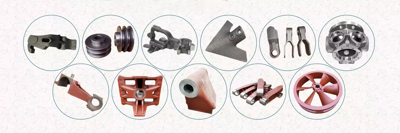
Agricultural Machinery
Agricultural machinery parts are critical to the overall operation of a farm or ranch. Replacement parts are essential if your equipment is not functioning as expected. CZPT's consumables experts are ready to help you find the right replacement parts for your equipment. You can rely on our knowledgeable staff to provide you with fast and accurate replacement services. If your agricultural machinery needs replacement parts, please contact us for assistance.
Key drivers of the agricultural machinery market include high global demand for food, rapid crop production, access to resources, and availability of credit. Agricultural machinery is mainly manufactured in Europe, the United States, Japan and China. Overall, we expect the agricultural machinery market to exceed $118 billion by 2025. Additionally, agricultural machinery OEM components are expected to grow at a CAGR of 3.6% over the next 5 years.
Agricultural machinery accessories include accessories and accessories other than tractor accessories. Plows loosen the soil and kill surface vegetation, fertilizer spreaders apply fertilizer evenly, rakes agitate the soil, and seeders sow seeds. Other accessories include balers, which collect materials and bundle them into management packs. Transplanters are used to transplant plants from 1 location to another. It must be properly maintained to maximize its useful life.
Farm machinery accessories can be found in all types of farming. From sowing to harvesting, farm machinery equipment is necessary to help farmers in various agricultural activities. Without mechanization, farming would not be as profitable as it is today. In Iran, Coulisse produces agricultural machinery parts including harrows, tillers, grain refiners, spinning machines and threshers. You can also find farm machinery accessories for sale through these companies.
A well-known brand in the field of agricultural machinery is New Holland. Parts can be found for New Holland and Case IH models. The company also produces replacement parts for many different models. The company's extensive dealer network spans more than 160 countries. PDF also supplies agricultural machinery parts for brands such as Ford and New Holland. If you are looking for reliable quality and cost-effective agricultural machinery, we can get the parts you need from these brands.
Agricultural Equipment
Growing population and demand for equipment drive the demand for agricultural equipment in Asia. In countries with limited land such as India, low-paying agricultural jobs are not enough for many farmers. At the same time, Australia has a large amount of agricultural land, but the reduction of agricultural labor has led to the increasing mechanization and integration of agricultural production. This, in turn, has fueled a surge in demand for Australian agricultural products in Asia, particularly in China and India.
Tractor transplanter is a common agricultural equipment. Tractors pull on these machines, which dig holes and put plants into the holes. A cultivator is another type of agricultural equipment that tills the soil and controls weeds. Smaller operations often use a cultivator. Large plastic farms, on the other hand, need to invest in cladding, using a series of wheels to lay down a layer of plastic.
Agricultural machinery is widely used. For example, tractors can carry heavy agricultural attachments such as haymakers and grain turbines. Farm equipment also helps farmers prepare soil for growing and harvesting large quantities of crops. It also helps transport food to other regions for processing. These machines make farming easier and more efficient. With all these benefits, it's no wonder so many people engage in farming as a profession. The world needs food and agriculture, and agricultural equipment is an integral part of the process.
Agricultural equipment operators use heavy agricultural machinery every day. They inspect the equipment and make minor repairs to keep it running smoothly. They also monitor the working environment and working conditions around the equipment. Depending on the field, agricultural equipment operators can operate a variety of agricultural equipment, load and unload products, and even harvest crops. These workers may spend most of the year working outdoors, which can take a long time. The average workweek for an agricultural equipment operator is approximately 18 hours.
Agricultural equipment operators often gain practical experience on the job. Some jobs in the industry may require a high school diploma, and students without a high school diploma can work on farms to learn the skills needed for the position. The industry requires employees to be properly trained and certified to operate equipment safely. AWS certification is highly recommended. All Associate of Applied Science in Agricultural Production Systems include core business and management courses applicable to the agricultural industry. 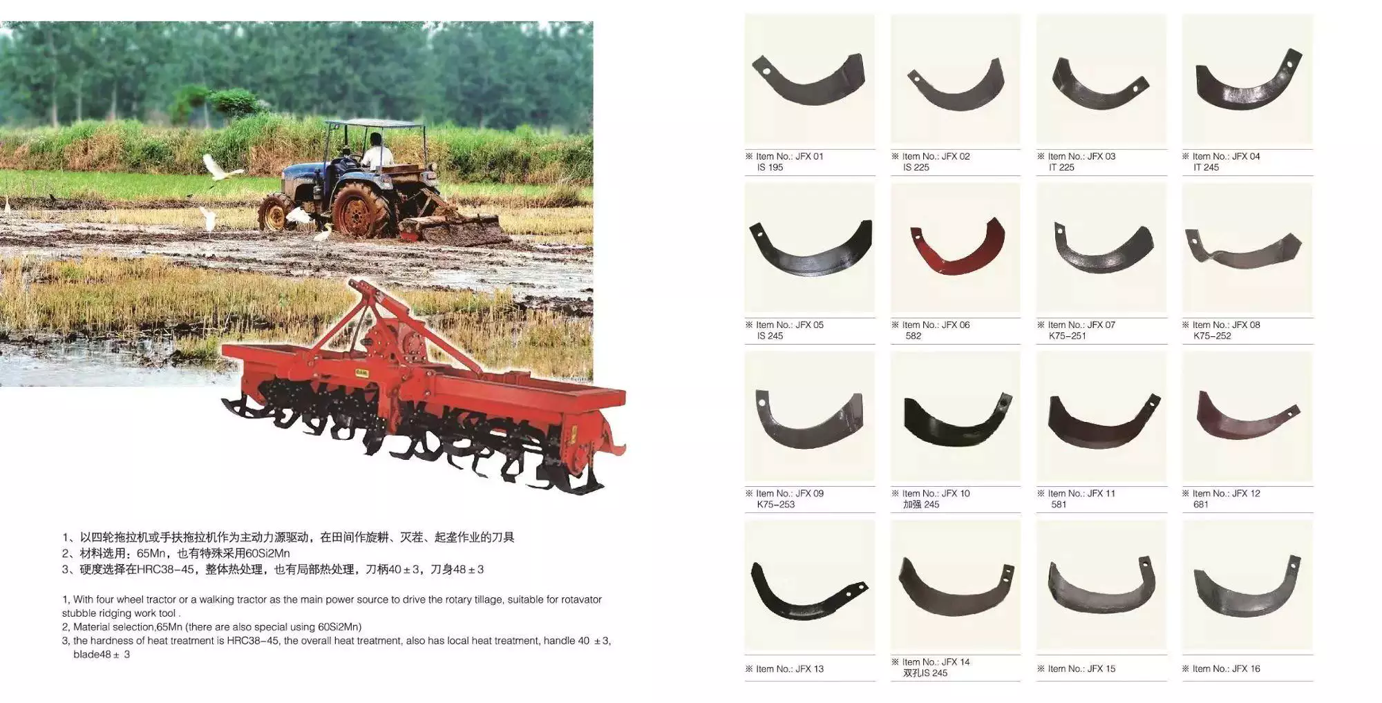
Agricultural machinery manufacturers
Agricultural machinery manufacturers produce agricultural implements such as tractors and combines for agricultural purposes. The production of these machines increases the productivity and efficiency of farmers around the world. These machines and parts increase the quality and quantity of crop production while reducing labor costs. They also help improve soil fertility. It's important to choose the right type of machine for your farm because not all farm machinery is the same. There are many high-quality agricultural machinery manufacturers in China, whose prices are competitive with the local market prices.
The growth of the agricultural machinery market is mainly driven by the growing global food demand. Agricultural equipment manufacturers are investing in precision-based technologies, which allow them to build better agricultural machines. In addition, OEM parts manufacturers focus on the safety, quality and continuous improvement of agricultural machinery parts. With the shift in focus, the agricultural machinery market is expected to make great strides in the coming years. Along with these improvements, the demand for agricultural machinery OEM parts is expected to grow at an annual rate of over 3%.
Yuantong Group: This agricultural machinery manufacturer has more than 20 overseas service centers around the world. The company is committed to providing excellent customer service and provides a warranty on all of its products. Yuantong Machinery's space parts are easily available at their service center. Shandong CZPT Heavy Industry International, a Chinese agricultural machinery manufacturer, was established in 1998 and is headquartered in Weifang City, Shandong Province.
Although the agricultural machinery industry is growing, the market is still affected by the economic downturn. The COVID-19 pandemic has put pressure on farming operations, who may forgo buying expensive equipment. Private investment in industrial equipment is also falling and is expected to decline further in 2020 and 2021. On the other hand, aftermarket agricultural machinery parts are tailored for an exact fit and outperform OEM parts.
Agricultural Machinery Suppliers
Agricultural Machinery Suppliers have a wide variety of products. From large farm machines to small ones, you'll find it all in 1 place. In addition to providing first-class machinery, agricultural machinery suppliers can also provide you with spare parts. Shandong Heavy Industry International, for example, is China's largest agricultural machinery maker, with annual sales of $9 billion. The company is headquartered in Weifang, Shandong and has been operating for more than 6 years.
Most farm equipment consists of hundreds of parts. For example, a typical tractor has more than 1,700 parts. Manufacturers have been shifting to just-in-time delivery of parts and raw materials. While the system works for predictable supply chains, it can break down when 1 component fails. Therefore, the best way to avoid problems and maximize profits is to get a list of Indian agricultural machinery suppliers through a dedicated marketplace.
Therefore, there are many suppliers of agricultural machinery. Some of the biggest names in the industry include CZPT and Caterpillar, both of which employ thousands of people. CZPT also offers a complete line of walk-behind and riding mowers, as well as log splitters and snow blowers. In addition, the German-made CZPT tractor line is being launched in Brazil. Finally, some smaller agricultural machinery enterprises produce and sell agricultural machinery.
In the next decade, the global agricultural machinery market will grow moderately. But in the short term, crop prices are expected to fall, which will negatively affect agricultural income and the agricultural machinery market. Experts predict that this will affect the demand for agricultural machinery. These factors will continue to influence the market and help farmers make better decisions. However, no single factor can guarantee that the agricultural machinery industry will not be affected by economic changes.
In addition to tractors, other types of agricultural machinery are also widely used for agricultural purposes. Tractors are the most common type of agricultural machinery and include rotary tillers, power tillers, subsoilers and trowels. Other equipment used for planting includes planters, planters and irrigation systems. Some specialized equipment includes sprinkler systems, micro sprinklers, and soil spray technology.
China supplier Metal Hydraulic Damper Soft Closing Oil Cylinder for Drawer Slide Door with Free Design Custom
Product Description
| Name | Cabinet Buffer Furniture Soft Close Sliding Door Damper | ||||
| 1.100,000 times -passed fatigue test | |||||
| 2. SGS Cerifty | |||||
| 3.Passed ISO9001 International Quality System Certification | |||||
| Use | Automobile;Auto,car;Furniture;Tool Box;Machines,mechanical equipment; Boat,container,etc. | ||||
| Material | Plastic/Iron | ||||
| Color | Grey/black/others | ||||
| Connector | ball connector/metal eye/clevis and so on | ||||
| Advantage | 1.pass 180,000 times fatigue times | ||||
| 2.we can supply samples for free | |||||
| 3.Competitive price | |||||
| 4.Fast delivery time:1000 pcs 3 days | |||||
| The size can be made according the customer requirment | |||||
For you refer how to choose reasonable diameter as pressure
| Extended length | Stroke | DIA | Force |
| 100-300 | 30-100 | 12*4 | 5-100N |
| 300-600 | 100-200 | 15*6 | 10-300N |
| 600-900 | 200-300 | 18*8 | 50-600N |
| 900-1200 | 300-400 | 22*10 | 100-1200N |
| 1200-1600 | 400-500 | 25*12 | 100-1800N |
| 1600-2000 | 500-600 | 28*14 | 100-3000N |
| 2000-2500 | 600-700 | 28*16 | 100-3000N |
| 2500-3000 | 700-900 | 40*20 | 300-4000N |
| The size can be made according the customer requirment. | |||
Technical Requirements:
1.Our gas spring according to the standard of GB/T 25751-2571;GB/T 25750-2571 or produce by customers' requirements.
2.Cylinder:20#, black paint on surface, smooth coating, no grinning, no aberration.
3.Piston rod:45#,the surface is treated by chemical deposition for Ni- P alloy,72h salt spray resistance
4.The gas spring have no block and abnormal sound during working.
Multiple Connectors,Switch and other accessory
Application
About Our Factory
Packing & Shipping
FAQ
1. Q1: What is our factory product range?
A1: Furniture Gas Spring; Office Chair Gas Lift; Supporting Gas Spring; Locking Gas Spring; Auto Gas Spring;
Any stop Gas Spring; Traction Gas Spring; Hydraulic Damper; Kitchen door buffer; End Fittings etc.
Q2: What's your MOQ of this gas spring?
A2: 100pcs.Small quantity is available .
Q3: Is it all right to make customer's own brand name?
A3: that's all right. if customer required, we'll make customer's brand name. otherwise we make our own brand
name.
Q4: How is the lead time of our order?
A4: For Sample3-7days , for Order the lead time is according to the quantity.
Q5: Can we visit your factory before we order from you ?
A5: Yes,welcome ! That is our pleasure to be visited.
.
Q6: Do you provide samples ? is it free or extra ?
A6: Yes, some product can offer the sample for free charge, and some product sample is not free, but do not pay
the cost of freight.
How to Choose the Right Worm Shaft
You might be curious to know how to choose the right Worm Shaft. In this article, you will learn about worm modules with the same pitch diameter, Double-thread worm gears, and Self-locking worm drive. Once you have chosen the proper Worm Shaft, you will find it easier to use the equipment in your home. There are many advantages to selecting the right Worm Shaft. Read on to learn more.
Concave shape
The concave shape of a worm's shaft is an important characteristic for the design of a worm gearing. Worm gearings can be found in a wide range of shapes, and the basic profile parameters are available in professional and firm literature. These parameters are used in geometry calculations, and a selection of the right worm gearing for a particular application can be based on these requirements.
The thread profile of a worm is defined by the tangent to the axis of its main cylinder. The teeth are shaped in a straight line with a slightly concave shape along the sides. It resembles a helical gear, and the profile of the worm itself is straight. This type of gearing is often used when the number of teeth is greater than a certain limit.
The geometry of a worm gear depends on the type and manufacturer. In the earliest days, worms were made similar to simple screw threads, and could be chased on a lathe. During this time, the worm was often made with straight-sided tools to produce threads in the acme plane. Later, grinding techniques improved the thread finish and reduced distortions resulting from hardening.
When a worm gearing has multiple teeth, the pitch angle is a key parameter. A greater pitch angle increases efficiency. If you want to increase the pitch angle without increasing the number of teeth, you can replace a worm pair with a different number of thread starts. The helix angle must increase while the center distance remains constant. A higher pitch angle, however, is almost never used for power transmissions.
The minimum number of gear teeth depends on the angle of pressure at zero gearing correction. The diameter of the worm is d1, and is based on a known module value, mx or mn. Generally, larger values of m are assigned to larger modules. And a smaller number of teeth is called a low pitch angle. In case of a low pitch angle, spiral gearing is used. The pitch angle of the worm gear is smaller than 10 degrees.
Multiple-thread worms
Multi-thread worms can be divided into sets of one, two, or 4 threads. The ratio is determined by the number of threads on each set and the number of teeth on the apparatus. The most common worm thread counts are 1,2,4, and 6. To find out how many threads you have, count the start and end of each thread and divide by two. Using this method, you will get the correct thread count every time.
The tangent plane of a worm's pitch profile changes as the worm moves lengthwise along the thread. The lead angle is greatest at the throat, and decreases on both sides. The curvature radius r" varies proportionally with the worm's radius, or pitch angle at the considered point. Hence, the worm leads angle, r, is increased with decreased inclination and decreases with increasing inclination.
Multi-thread worms are characterized by a constant leverage between the gear surface and the worm threads. The ratio of worm-tooth surfaces to the worm's length varies, which enables the wormgear to be adjusted in the same direction. To optimize the gear contact between the worm and gear, the tangent relationship between the 2 surfaces is optimal.
The efficiency of worm gear drives is largely dependent on the helix angle of the worm. Multiple thread worms can improve the efficiency of the worm gear drive by as much as 25 to 50% compared to single-thread worms. Worm gears are made of bronze, which reduces friction and heat on the worm's teeth. A specialized machine can cut the worm gears for maximum efficiency.
Double-thread worm gears
In many different applications, worm gears are used to drive a worm wheel. These gears are unique in that the worm cannot be reversed by the power applied to the worm wheel. Because of their self-locking properties, they can be used to prevent reversing motion, although this is not a dependable function. Applications for worm gears include hoisting equipment, elevators, chain blocks, fishing reels, and automotive power steering. Because of their compact size, these gears are often used in applications with limited space.
Worm sets typically exhibit more wear than other types of gears, and this means that they require more limited contact patterns in new parts. Worm wheel teeth are concave, making it difficult to measure tooth thickness with pins, balls, and gear tooth calipers. To measure tooth thickness, however, you can measure backlash, a measurement of the spacing between teeth in a gear. Backlash can vary from 1 worm gear to another, so it is important to check the backlash at several points. If the backlash is different in 2 places, this indicates that the teeth may have different spacing.
Single-thread worm gears provide high speed reduction but lower efficiency. A multi-thread worm gear can provide high efficiency and high speed, but this comes with a trade-off in terms of horsepower. However, there are many other applications for worm gears. In addition to heavy-duty applications, they are often used in light-duty gearboxes for a variety of functions. When used in conjunction with double-thread worms, they allow for a substantial speed reduction in 1 step.
Stainless-steel worm gears can be used in damp environments. The worm gear is not susceptible to rust and is ideal for wet and damp environments. The worm wheel's smooth surfaces make cleaning them easy. However, they do require lubricants. The most common lubricant for worm gears is mineral oil. This lubricant is designed to protect the worm drive.
Self-locking worm drive
A self-locking worm drive prevents the platform from moving backward when the motor stops. A dynamic self-locking worm drive is also possible but does not include a holding brake. This type of self-locking worm drive is not susceptible to vibrations, but may rattle if released. In addition, it may require an additional brake to keep the platform from moving. A positive brake may be necessary for safety.
A self-locking worm drive does not allow for the interchangeability of the driven and driving gears. This is unlike spur gear trains that allow both to interchange positions. In a self-locking worm drive, the driving gear is always engaged and the driven gear remains stationary. The drive mechanism locks automatically when the worm is operated in the wrong manner. Several sources of information on self-locking worm gears include the Machinery's Handbook.
A self-locking worm drive is not difficult to build and has a great mechanical advantage. In fact, the output of a self-locking worm drive cannot be backdriven by the input shaft. DIYers can build a self-locking worm drive by modifying threaded rods and off-the-shelf gears. However, it is easier to make a ratchet and pawl mechanism, and is significantly less expensive. However, it is important to understand that you can only drive 1 worm at a time.
Another advantage of a self-locking worm drive is the fact that it is not possible to interchange the input and output shafts. This is a major benefit of using such a mechanism, as you can achieve high gear reduction without increasing the size of the gear box. If you're thinking about buying a self-locking worm gear for a specific application, consider the following tips to make the right choice.
An enveloping worm gear set is best for applications requiring high accuracy and efficiency, and minimum backlash. Its teeth are shaped differently, and the worm's threads are modified to increase surface contact. They are more expensive to manufacture than their single-start counterparts, but this type is best for applications where accuracy is crucial. The worm drive is also a great option for heavy trucks because of their large size and high-torque capacity.
China factory Hydraulic Cylinder for Hydraulic Shear with Free Design Custom
Product Description
Product Description
We manufacture all kinds of cylinder and hydraulic station for steel mills metallurgical equipments based on client requirement.
| Max Tube Dia.: | 1000mm | ||
| Max. Rod Dia.: | 600 mm | ||
| Max. Stroke: | 10 meters | ||
| Production Capacity: | 200,000 pcs per year | ||
Advantages of Ball Screws and How They Can Benefit Your Applications
When selecting a ball screw for your application, there are several factors to consider. This article will discuss high mechanical efficiency, low friction, multiple repair options, and application requirements. Choosing the right ball screw can help you get the job done quickly and effectively. To make your decision easier, consider the following tips. Read on to learn about some of the advantages of ball screws and how they can benefit your applications. Here are some of the most common types: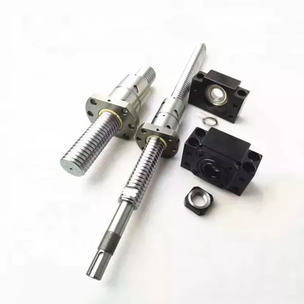
High mechanical efficiency
The mechanical efficiency of ball screws can be measured using the axial load test. The axial load is equal to 0.5 x FPr / 2Fpr. The elastic deformations are measured as DL1 and DL2, respectively. Common engineering procedures work at 90 percent reliability; however, certain sectors require higher reliability, which has a direct impact on the dynamic load capacity. The axial load test is 1 of the most widely used methods to determine the mechanical efficiency of ball screws.
In order to achieve high translation, ball screws must be designed with high stiffness and positioning accuracy. In addition, high preloads increase the initial driving torque and cause more friction and heat. Other important design criteria include low driving torque and reduced slip motion. This means that the high translation capacity of ball screws must be well matched to the overall application. The following are some common design criteria for ball screws. You can select the best type of ball screw for your needs.
The high mechanical efficiency of ball screw is achieved by avoiding the common sag and pitch problem. The ball track design helps to reduce the centrifugal force. The ball screw's diameter can be adjusted by adjusting the centre pitch of the nut on 2 ball tracks. The nut's axial load is also adjusted through the offset centre pitch. This method allows the users to increase the mechanical efficiency of ball screw by up to 40%.
When calculating the mechanical efficiency of ball screw, consider the application's environment, speed, and other factors. If the application requires precision and accuracy, then the ball screw is the right choice. The engineering department of a ball screw manufacturer will carefully review the application factors and come up with a design that meets the application's expectations. Moreover, some manufacturers even offer customized ball screws, which can be tailored to your requirements.
Low friction
The operating performance of a low-friction ball screw is characterized by its minimal friction. This screw has a structure that transmits forces through rolling steel balls. The torque is calculated by calculating the load and the lead screw's dimensions. This type of screw can be used for a variety of different applications, including hydraulic systems. Read on to learn more about this type of screw and how it can help you build a more reliable and durable car.
The critical speed of a ball screw is higher than that of a lead screw, so this type of screw can accommodate larger loads and speeds. It also has a lower friction coefficient, which reduces the amount of heat produced. High-quality ball screws can withstand longer duty cycles than standard lead screws. However, in order to compare the two, you must take into account the duty cycle. Low-friction ball screws are more durable than lead screws, and the duty cycle is only 1 of the factors you should consider when selecting them.
The ball bearings are the most prominent component of a low-friction ball screw. Their main function is to reduce the friction between the nut and the shaft. Without them, the friction would be too high. This feature is possible thanks to the ball bearing's groove profile. Two arcs intersect at the contact points on the shaft and nut. Consequently, the ball bearing reduces friction in a way that is essentially non-existent without the bearing.
The mechanical efficiency of a low-friction ball screw is very high. The typical ball screw is up to 90% efficient, but some types can reach a higher efficiency. They are commonly used in machine slides, presses, and linear actuators. The high efficiency of a low-friction ball screw makes it a great choice for many different applications. This type of screw is made of several main components. The ball bearings provide the helical raceway for the ball assembly and threaded shaft is the screw part. The ball screw is comparatively more bulky than a conventional leadscrew, but the overall size is smaller than its lead counterpart.
Multiple repair options
A damaged ball screw will typically display visible physical signs, including noise or vibration. Additionally, worn ball screws will require more horsepower and torque to operate. They may also cause lead accuracy issues. Luckily, there are multiple repair options for ball screws. You can get new ball screws to restore preload and reduce backlash. But there are some warning signs to look out for first. Keeping a close eye on your ball screw's health can help you avoid a costly replacement.
Look for a ball screw repair company with a proven track record of servicing all types of ball screws. The service should offer a free evaluation and 3 types of service: reload, recondition, and replacement. Reload is the simplest option and involves cleaning and polishing the screw and ball nut. Reconditioning or replacement, on the other hand, requires new parts. Choose the 1 that offers the best value for your money.
EP offers an emergency service and superior service for your ball screws. Their UK service includes delivery and international shipping. All ballscrew repairs are covered by a full service warranty, and the company is known for providing competitive pricing. If you do need a ball screw repair, look no further. Contact K+S today to discuss your specific needs. You'll be glad you did. You'll save up to 70% over purchasing a new ball screw.
While ball screw repair is an easy and inexpensive option, it may be necessary to have it replaced more frequently than the usual. In addition to replacing worn ball screws, you may need to consider a different type of repair. This process involves grinding the ball nut and journal diameters back to their original size. Fortunately, level 4 is the most expensive but can restore a screw's lifespan. This is also the most extensive type of repair available for a ball screw.
Application requirements
A ball screw is an efficient solution for precision motion control in many applications, including automotive and aerospace. These screw-type devices are highly resistant to corrosion, and the alternating steel-ceramic architecture ensures extreme reliability and sturdiness. For the aerospace sector, a ball screw replaces the typical hydraulic system, and the product is used in wind turbine blade pitch and directional position, solar panel movement, and gate control in hydroelectric stations. Ball screws are also used in motorised inspection tables, step photolithography machines, microscopic integrated circuits, and many other applications.
The most critical requirements for a ball screw assembly are backlash and bearing support. Backlash is the amount of axial motion between the screw and nut, which leads to positioning errors. Although this axial motion is minimal, it can be as little as 70um. If the preload is too large, a ball screw may suffer from excessive heat. Depending on the application, the amount of preload required can be adjusted to maximize the overall performance of the device.
The choice of screw is determined by the load capacity. For example, plastic nuts are commonly used for light loads, while bronze nuts are used for loads that weigh several thousand pounds. Lead screws are not particularly reliable in situations where load requirements are extremely high, and a ball screw will often be a better option. The lower friction of a ball screw allows it to withstand higher duty cycles than a lead screw. When the load requirements exceed lead screws' capacity, a ball screw is the better choice.
A step photolithography machine is another example of an application where ball screws play an important role. This device helps manufacturers produce microscopic integrated circuits by harnessing the reaction of light. A stepper is a critical piece of this machine, as it controls the positioning of light exposure on the silicon wafer. High precision is required for this application. Ultimately, a ball screw will make the process easier. Its proven record for meeting instrumentation requirements is an excellent example of its value in the laboratory.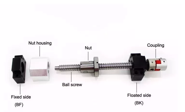
Cost
The global market for ball screws is growing at a steady pace, but what drives the growth? In the ball screw industry, performance, cost, and analytical predictability are the primary concerns of OEMs. This market study provides in-depth analysis of these market dynamics. You'll learn how to best compete in the global market for ball screws. Here are some tips to help you get started:
Ensure you have a good grasp of the differences between lead and ball screws. The cost of lead screws depends on their efficiency, and some of them can achieve C5 level accuracy. However, ball screws are more durable and more repeatable. Besides, lead screws can't achieve high precision because of their sliding motion, which gradually grinds away the accuracy. As a result, the cost of a ball screw is more than compensated by the improved performance of OEMs.
To get the best price for ball screw, look for a manufacturer with a strong technical force. Most of these manufacturers have sophisticated equipment and strict quality control systems. They draw inspiration from the requirements of the market and have continuously increased their technological content to stay ahead of the competition. If you're in Pune, look for a manufacturer with this technology. It won't be difficult to do business with such a supplier. The company will also provide you with contact information, including their office address and phone numbers.
When choosing between lead and ball screws, you need to understand how they work and why they're more reliable. Ball screws are more durable than lead screws, which is 1 of the primary reasons for their popularity. Lead screws, on the other hand, are often used for vertical applications. Lead screws tend to be cheaper than ball screws, but they have more limitations. When used properly, however, they can increase the life and performance of machines. In general, they're corrosion-resistant and offer great design flexibility.