Product Description
SRC Series Swing Clamp Hydraulic Brake Turn Direction 90 Degree Automation Rotation Pneumatic Rotary Cylinder
| Product type | Rotary Cylinder |
| Model | SRC |
| Production time | 5-7days after payment made |
| Sample order | Available |
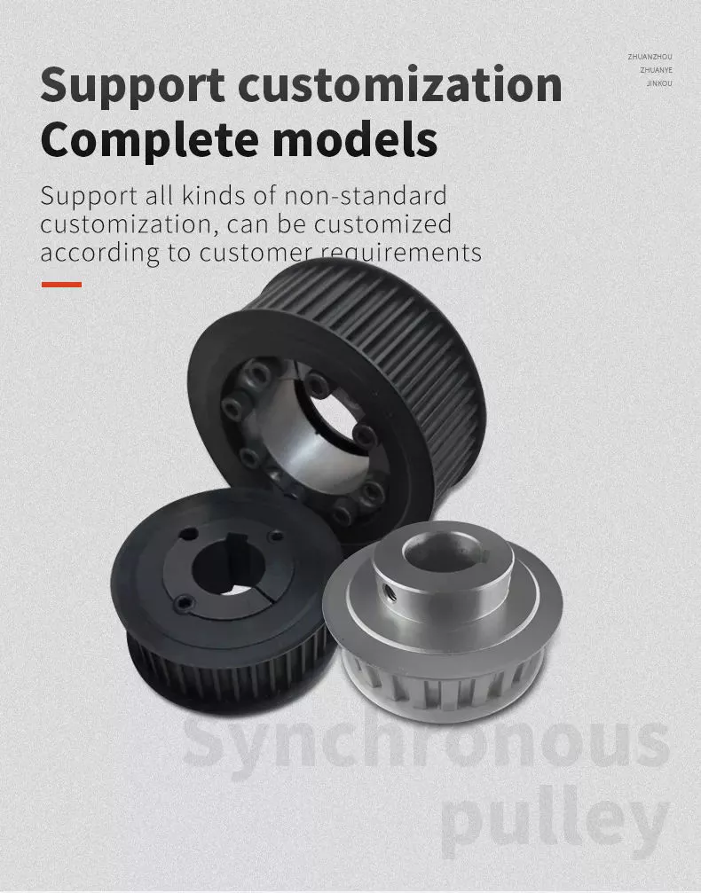
| Customize | Available |
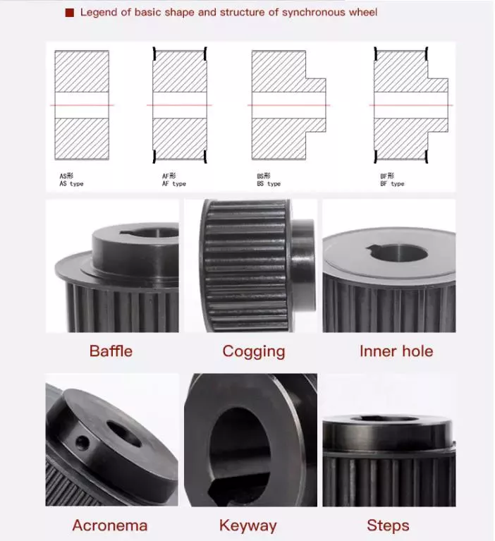
Advantages and disadvantages of different types of bushings
Bushings are a simple but essential part of machinery with sliding or rotating shaft assemblies. This type of bearing is used in a wide variety of industries because its high load-carrying capacity and excellent anti-friction properties make it a necessity for construction, mining, hydropower, transportation and agricultural machinery. In addition to these applications, bushings also play a vital role in material handling and food processing. This article explores the various types of bushings available.
air casing
The air bushing forms a frictionless cylinder that applies the load to the rotating object. Bushings are used to measure torque and provide self-centering force in applications where linear motion is critical. The following are load equations that can be used to select the appropriate air sleeve for your application. To learn more about these air sleeves, read on. This article discusses the benefits and uses of air bushings in linear motion.
Bushings have many advantages over bearings. They are not prone to wear and corrosion. Unlike bearings, they can easily bypass conversion and inspection periods. Their high-quality design guarantees reliable machine performance, yet they are inexpensive and easy to replace. In many industries, air compressors are essential for sports. The air bushing eliminates friction, allowing the compressor to work more efficiently. They can also help eliminate the need for frictionless bearings and improve the overall efficiency of the machine.
Another type of air bearing is the cylindrical bushing. These are used for linear and aerostatic motion. Their low friction properties allow them to support radial loads without wearing out or damaging components. They are usually used for normal sized shafts. Air bushings have several components that can be used with other types of air bearings. Cylindrical air bearings have 4 o-ring grooves that allow them to be inserted into the structure. They are often used with other types of air bearings for smoother motion.
rubber bushing
If you're looking to buy a new suspension system, you may be wondering if rubber or polyurethane is the right choice. Rubber is less expensive, but not without its drawbacks. Polyurethane is more durable and offers better handling and suspension. Rubber bushings also reduce road feel, while polyurethane isolates the driver from the road. Both materials will help you improve handling and alignment, but each has advantages and disadvantages.
Typically, rubber bushings are cylindrical components with metal inner and outer surfaces. These metals can be stainless steel, mild steel or aluminum. They are usually stress relieved and prestressed for maximum durability. They are designed to meet the exact specifications of a specific application. For example, shock-absorbing rubber bushings are cushioning pads made of polyurethane that absorb road bumps and noise.
Unlike polyurethane, rubber suspension bushings have a shorter lifespan than polyurethane. This is because rubber is more susceptible to damage from UV rays, road chemicals and oils. The rubber also stretches and warps due to the pressure of the road. The rubber bushing also squeaks, which can be cause for concern. But if the noise persists for a long time, it may be a sign that your vehicle needs a new suspension system.
The main reason why cars use rubber bushings is for shock absorption. During machine use, vibration and noise caused by the movement of parts can cause serious damage. To prevent this, rubber bushings act as shock absorbers and damping agents. Rubber bushings are an excellent choice for automakers, but they are also used in a variety of industrial settings.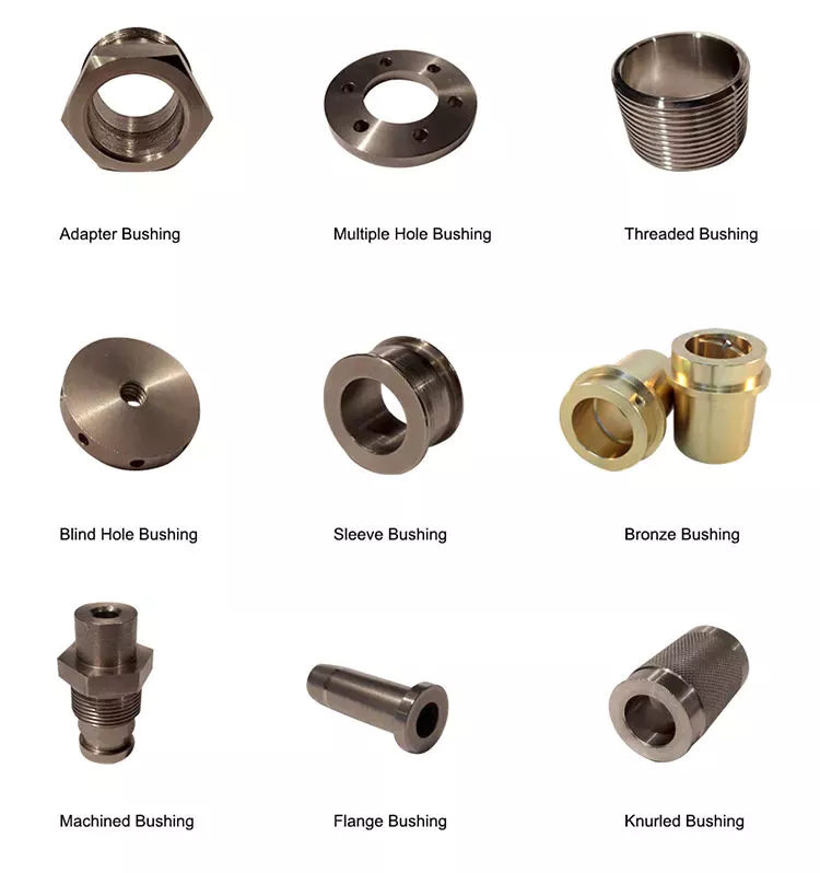
Polyurethane bushing
If you want to make your vehicle handle better, polyurethane bushings may be the answer. They come in different shapes and sizes and can improve a wide range of areas. This article will explore the advantages and disadvantages of polyurethane bushings and their potential place in your car. However, before you decide to upgrade your suspension, you should understand the various advantages and disadvantages of polyurethane bushings.
The main difference between a polyurethane bushing and a rubber bushing is how the bushing rides on the suspension arm. Polyurethane bushings do not have faces that slide against each other like rubber bushings. This means they allow for more rotation and flexion, as well as consistent alignment of the control arms. Polyurethane bushings require lubrication, but only need to be lubricated every 5 years, much longer than equivalent rubber bushings.
Another difference between polyurethane and rubber bushings is hardness. The former has the least elasticity and is generally the most suitable for street use. While rubber bushings provide the best NVH quality, they are also notorious for changing suspension geometry. Rubber is known to be an excellent choice for street use, but polyurethane has a lifespan that far outlasts rubber.
bronze bushing
There are 2 main types of bronze bushings, sintered and cast. The latter require additional lubrication and are typically used in applications where powder metal products cannot be secured. The former is cheaper than the latter, but the process is more expensive. Bronze bushings can be used in environments where the material will be exposed to high temperature and vibration. For these reasons, the production process is relatively slow and expensive.
The strength of bronze is the main reason why they are so popular. Brass is a softer metal that deforms and corrodes easily. The bronze casing can withstand continuous immersion in water and can last for hundreds of years with little or no maintenance. However, it is important to note that this metal is not resistant to aggressive chemicals and requires regular maintenance to keep it in good condition.
Bronze bushings offer many advantages, including durability and aesthetics. Bronze bushings are available in a variety of sizes and can be ordered in imperial and metric sizes. They can be built to your specifications and are very durable. You can even custom order them if you want. And because they can be customized, they are an excellent choice for high-end applications. The quality of the bronze bushings is second to none.
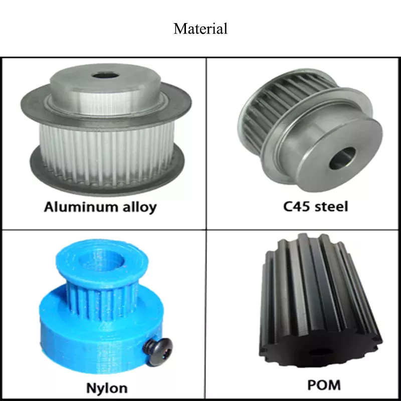
Plastic bushing
Engineered composite plastic bushings have been shown to last longer than bronze bushings and have also been found to reduce maintenance costs by up to 40%. Plastic bushings have become the first choice for thousands of applications, including medical equipment, food processing machinery, pumps, and more. Bronze bushings are oil-impregnated, but their performance is limited by their inherent weaknesses: oil-impregnated bronze tends to develop high levels of capillary action and requires rotational motion to maintain an intact oil film. Low speed and intermittent use of bronze bushings can also hinder the ability of the lubricant to provide adequate lubrication.
Advantages of plastic bushings over metal include low friction, non-reactive surfaces, and long life. CZPT offers a variety of engineering plastics that outperform traditional metals in a range of applications. For example, nylon bushings resist wear while requiring little lubrication. In addition, polymer-shaped plastics are lightweight and highly resistant to aggressive cleaning agents and chemicals.
Besides being less expensive than metal bushings, plastic bushings offer many other advantages. They are very durable, have a low coefficient of friction, and are more wear-resistant than metal. Unlike metal, plastic bushings do not require lubrication and do not absorb dust and oil like metal bushings. They are lightweight, easy to maintain and last longer. This makes them an excellent choice for many applications.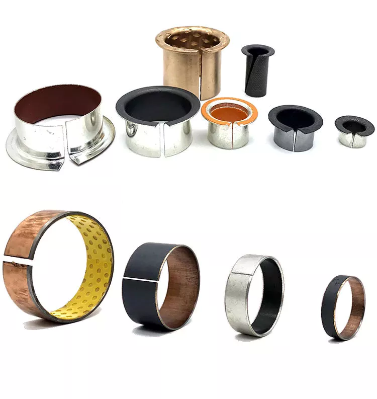
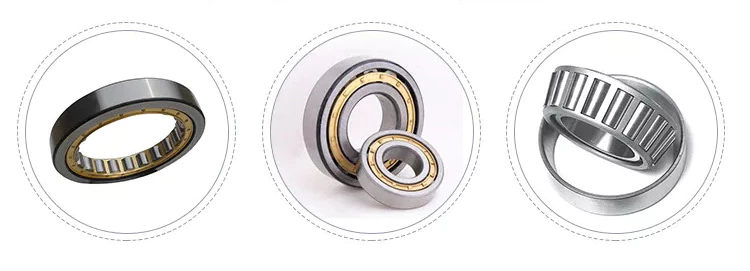
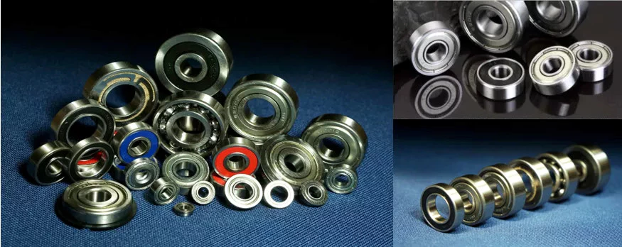
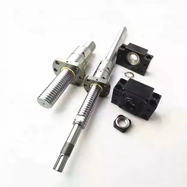
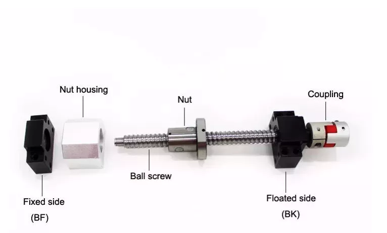
Sleeve bearing
Sleeve bearings are simple pipes with matching components. They facilitate linear motion by absorbing friction and vibration. They can withstand heavy loads and work at high temperatures for long periods of time. Flange bearings are similar to sleeve bearings, but are enclosed and rotated in a housing unit. Sleeve bearings have higher load-carrying capacity and resistance to shock loads. Furthermore, they are lightweight and low cost.
Another name for sleeve bearings is babbitt radial bearings. These bearings are usually made of bronze and have straight inner and outer diameters. They are also impregnated with oil and can withstand radial loads. Typical uses for sleeve bearings are agriculture, automotive and machine tools. Sleeves can also be solid or cored material, depending on the intended use.
The type of sleeve bearing used in the bushing is important in determining which type of bushing to buy. Sleeve bearings are sized based on pressure and speed considerations. Typically, the PV limit is an upper bound on the combined pressure and velocity for a given casing material. In some cases, the sleeve bearing used in the bushing is the same as the plain bearing.
Sleeve bearings are simple in design and made from a variety of materials, including bronze and plastic. They are more affordable than metal, but plastic is still not inaudible. Plastic sleeve bearings will rattle like metal bearings if the gap between the 2 bushings is not accurate. Additionally, high temperature electronic painting can permanently thin the casing. The stainless steel backing provides a good surface for electronic painting and enhances abrasion resistance.