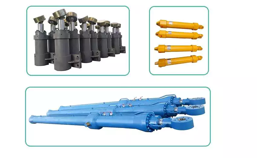
Product Description
| long stroke telescopic hydraulic cylinders | |||
| Part number | Tube dia mm | Rod dia mm | Stroke mm |
| 205-63-57100 | 120 | 85 | 1285 |
| 206-63-57100 | 120 | 85 | 1285 |
| 205-63-57160 | 120 | 85 | 1285 |
| 205-63-57120 | 135 | 95 | 1490 |
| 203-63-57130 | 125 | 85 | 1120 |
| 203-63-57131 | 125 | 85 | 1120 |
| 205-63-57130 | 125 | 85 | 1120 |
Specifications
1.Supply to USA,Europe,and Australia, Russia.
2.Material:Stainless Steel
3.Professional performance excavator parts supplier
4. High quality and low price
FAQ
Q1: Are you Manufacture or Trade Company?
A1: We are manufacture,we have 20 years experience for supply Metal material and products in domestic.
Q2: How can we guarantee quality?
A2: Always a pre-production sample before mass production;Always final Inspection before shipment;
Q3: What is your terms of payment ?
A3: 1.T/T: 30% deposit in advance, the balance 70% paid before shipment
2.30% down payment, the balance 70% paid against L/C at sight
3.CHINAMFG negotiation
Q4: Can you provide Certificates for aluminum materials ?
A4:Yes,we can supply MTC-Material Test Certificate.
Q5: Can you provide sample?
A5: Yes, we can provide you sample, but you need to pay for the sample and freight firstly. We will return the sample fee after
you make an order.
| Certification: | GS, RoHS, CE, ISO9001 |
|---|---|
| Pressure: | Medium Pressure |
| Work Temperature: | Normal Temperature |
| Acting Way: | Double Acting |
| Working Method: | Piston Cylinder |
| Adjusted Form: | Switching Type |
| Customization: |
Available
|
|
|---|
How do hydraulic cylinders compare to other methods of force generation like electric motors?
Hydraulic cylinders and electric motors are two different methods of force generation with distinct characteristics and applications. While both hydraulic cylinders and electric motors can generate force, they differ in terms of their working principles, performance attributes, and suitability for specific applications. Here's a detailed comparison of hydraulic cylinders and electric motors:
1. Working Principle:
- Hydraulic Cylinders: Hydraulic cylinders generate force through the conversion of fluid pressure into linear motion. They consist of a cylinder barrel, piston, piston rod, and hydraulic fluid. When pressurized hydraulic fluid enters the cylinder, it pushes against the piston, causing the piston rod to extend or retract, thereby generating linear force.
- Electric Motors: Electric motors generate force through the conversion of electrical energy into rotational motion. They consist of a stator, rotor, and electromagnetic field. When an electrical current is applied to the motor's windings, it creates a magnetic field that interacts with the rotor, causing it to rotate and generate torque.
2. Force and Power:
- Hydraulic Cylinders: Hydraulic cylinders are known for their high force capabilities. They can generate substantial linear forces, making them suitable for heavy-duty applications that require lifting, pushing, or pulling large loads. Hydraulic systems can provide high force output even at low speeds, allowing for precise control over force application. However, hydraulic systems typically operate at lower speeds compared to electric motors.
- Electric Motors: Electric motors excel in providing high rotational speeds and are commonly used for applications that require rapid motion. While electric motors can generate significant torque, they tend to have lower force output compared to hydraulic cylinders. Electric motors are suitable for applications that involve continuous rotary motion, such as driving conveyor belts, rotating machinery, or powering vehicles.
3. Control and Precision:
- Hydraulic Cylinders: Hydraulic systems offer excellent control over force, speed, and positioning. By regulating the flow of hydraulic fluid, the force and speed of hydraulic cylinders can be precisely controlled. Hydraulic systems can provide gradual acceleration and deceleration, allowing for smooth and precise movements. This level of control makes hydraulic cylinders well-suited for applications that require precise positioning, such as in industrial automation or construction equipment.
- Electric Motors: Electric motors also offer precise control over speed and positioning. Through motor control techniques such as varying voltage, frequency, or pulse width modulation (PWM), the rotational speed and position of electric motors can be accurately controlled. Electric motors are commonly used in applications that require precise speed control, such as robotics, CNC machines, or servo systems.
4. Efficiency and Energy Consumption:
- Hydraulic Cylinders: Hydraulic systems can be highly efficient, especially when properly sized and designed. However, hydraulic systems typically have higher energy losses due to factors such as fluid leakage, friction, and heat generation. The overall efficiency of a hydraulic system depends on the design, component selection, and maintenance practices. Hydraulic systems require a hydraulic power unit to pressurize the hydraulic fluid, which consumes additional energy.
- Electric Motors: Electric motors can have high efficiency, especially when operated at their optimal operating conditions. Electric motors have lower energy losses compared to hydraulic systems, primarily due to the absence of fluid leakage and lower friction losses. The overall efficiency of an electric motor depends on factors such as motor design, load conditions, and control techniques. Electric motors require an electrical power source, and their energy consumption depends on the motor's power rating and the duration of operation.
5. Environmental Considerations:
- Hydraulic Cylinders: Hydraulic systems typically use hydraulic fluids that can pose environmental concerns if they leak or are not properly disposed of. The choice of hydraulic fluid can impact factors such as biodegradability, toxicity, and potential environmental hazards. Proper maintenance and leak prevention practices are essential to minimize the environmental impact of hydraulic systems.
- Electric Motors: Electric motors are generally considered more environmentally friendly since they do not require hydraulic fluids. However, the environmental impact of electric motors depends on the source of electricity used to power them. When powered by renewable energy sources, such as solar or wind, electric motors can offer a greener solution compared to hydraulic systems.
6. Application Suitability:
- Hydraulic Cylinders: Hydraulic cylinders are commonly used in applications that require high force output, precise control, and durability. They are widely employed in industries such as construction, manufacturing, mining, and aerospace. Hydraulic systems are well-suited for heavy-duty applications, such as lifting heavy objects, operating heavy machinery, or controlling large-scale movements.
- Electric Motors: Electric motors are widely used in various industries and applications that require rotational motion, speed control, and precise positioning. They are commonly found in appliances, transportation, robotics, HVAC systems, and automation. Electric motorsare suitable for applications that involve continuous rotary motion, such as driving conveyor belts, rotating machinery, or powering vehicles.In summary, hydraulic cylinders and electric motors have different working principles, force capabilities, control characteristics, efficiency levels, and application suitability. Hydraulic cylinders excel in providing high force output, precise control, and durability, making them ideal for heavy-duty applications. Electric motors, on the other hand, offer high rotational speeds, precise speed control, and are commonly used for applications that involve continuous rotary motion. The choice between hydraulic cylinders and electric motors depends on the specific requirements of the application, including the type of motion, force output, control precision, and environmental considerations.
Integration of Hydraulic Cylinders with Equipment Requiring Rapid and Dynamic Movements
Hydraulic cylinders can indeed be integrated with equipment that requires rapid and dynamic movements. While hydraulic systems are generally known for their ability to provide high force and precise control, they can also be designed and optimized for applications that demand fast and dynamic motion. Let's explore how hydraulic cylinders can be integrated with such equipment:
- High-Speed Hydraulic Systems: Hydraulic cylinders can be part of high-speed hydraulic systems designed specifically for rapid and dynamic movements. These systems incorporate features such as high-flow valves, optimized hydraulic circuitry, and responsive control systems. By carefully engineering the system components and hydraulic parameters, it is possible to achieve the desired speed and responsiveness, enabling the equipment to perform rapid movements.
- Valve Control: The control of hydraulic cylinders plays a crucial role in achieving rapid and dynamic movements. Proportional or servo valves can be used to precisely control the flow of hydraulic fluid into and out of the cylinder. These valves offer fast response times and precise flow control, allowing for rapid acceleration and deceleration of the cylinder's piston. By adjusting the valve settings and optimizing the control algorithms, equipment can be designed to execute dynamic movements with high speed and accuracy.
- Optimized Cylinder Design: The design of hydraulic cylinders can be optimized to facilitate rapid and dynamic movements. Lightweight materials, such as aluminum alloys or composite materials, can be used to reduce the moving mass of the cylinder, enabling faster acceleration and deceleration. Additionally, the cylinder's internal components, such as the piston and seals, can be designed for low friction to minimize energy losses and enhance responsiveness. These design optimizations contribute to the overall speed and dynamic performance of the equipment.
- Accumulator Integration: Hydraulic accumulators can be integrated into the system to enhance the dynamic capabilities of hydraulic cylinders. Accumulators store pressurized hydraulic fluid, which can be rapidly released to supplement the flow from the pump during high-demand situations. This stored energy can provide an extra boost of power, allowing for faster and more dynamic movements. By strategically sizing and configuring the accumulator, the system can be optimized for the specific rapid and dynamic requirements of the equipment.
- System Feedback and Control: To achieve precise and dynamic movements, hydraulic systems can incorporate feedback sensors and advanced control algorithms. Position sensors, such as linear potentiometers or magnetostrictive sensors, provide real-time position feedback of the hydraulic cylinder. This information can be used in closed-loop control systems to maintain precise positioning and execute rapid movements. Advanced control algorithms can optimize the control signals sent to the valves, ensuring smooth and dynamic motion while minimizing overshooting or oscillations.
In summary, hydraulic cylinders can be integrated with equipment that requires rapid and dynamic movements by utilizing high-speed hydraulic systems, employing responsive valve control, optimizing cylinder design, integrating accumulators, and incorporating feedback sensors and advanced control algorithms. These measures enable hydraulic systems to deliver the speed, responsiveness, and precision necessary for equipment operating in dynamic environments. By leveraging the capabilities of hydraulic cylinders, manufacturers can design and integrate systems that meet the requirements of applications demanding rapid and dynamic movements.
Can hydraulic cylinders be adapted for use in both industrial and mobile equipment?
Yes, hydraulic cylinders can be adapted for use in both industrial and mobile equipment. The versatility and adaptability of hydraulic systems make them suitable for a wide range of applications across various industries. Here's a detailed explanation:
1. Industrial Equipment:
- Hydraulic cylinders are extensively used in industrial equipment such as manufacturing machinery, construction equipment, material handling systems, and heavy-duty machinery. They provide the necessary force and controlled movement for tasks such as lifting, pushing, pulling, and positioning heavy loads. Industrial hydraulic cylinders are typically designed for robustness, durability, and high load-bearing capacities to withstand the demanding environments and heavy-duty applications encountered in industries.
2. Mobile Equipment:
- Hydraulic cylinders are also widely adopted in mobile equipment, including agricultural machinery, mining equipment, forestry machinery, and transportation vehicles. These cylinders enable various functions such as tilting, lifting, steering, and stabilizing. Mobile hydraulic cylinders are designed to be compact, lightweight, and efficient to meet the specific requirements of mobile applications. They are often integrated into hydraulic systems that power multiple functions in a single machine.
3. Adaptability:
- One of the key advantages of hydraulic cylinders is their adaptability. They can be customized and configured to suit different operating conditions, equipment sizes, load capacities, and speed requirements. Hydraulic cylinder manufacturers offer a wide range of sizes, stroke lengths, mounting options, and rod configurations to accommodate diverse applications. This adaptability allows hydraulic cylinders to be utilized in both industrial and mobile equipment, serving various purposes across different sectors.
4. Mounting Options:
- Hydraulic cylinders can be adapted to different mounting arrangements to suit the specific requirements of industrial and mobile equipment. They can be mounted in various orientations, including vertical, horizontal, or at an angle. Different mounting options, such as flange mounts, trunnion mounts, and clevis mounts, provide flexibility in integrating hydraulic cylinders into different equipment designs.
5. Integration with Hydraulic Systems:
- Hydraulic cylinders are often part of a larger hydraulic system that includes components such as pumps, valves, hoses, and reservoirs. These systems can be tailored to meet the specific needs of both industrial and mobile equipment. The hydraulic system's design and configuration can be adapted to provide the necessary flow rates, pressures, and control mechanisms required for optimal performance in the intended application.
6. Control and Automation:
- Hydraulic cylinders in both industrial and mobile equipment can be integrated with control systems and automation technologies. This allows for precise and automated control of the cylinder's movement and function. Proportional control valves, sensors, and electronic controls can be incorporated to achieve accurate positioning, speed control, and synchronization of multiple hydraulic cylinders, enhancing overall equipment performance and productivity.
7. Safety Considerations:
- Hydraulic cylinders for both industrial and mobile equipment are designed with safety in mind. They often feature built-in safety mechanisms such as overload protection, pressure relief valves, and emergency stop systems to prevent accidents and equipment damage. Safety standards and regulations specific to each industry are taken into account during the design and adaptation of hydraulic cylinders for different applications.
Overall, hydraulic cylinders offer the adaptability and performance required for use in both industrial and mobile equipment. Their versatility, customizable features, mounting options, integration capabilities, and safety considerations make them suitable for a wide range of applications across diverse industries. Whether it's heavy-duty industrial machinery or mobile equipment operating in challenging environments, hydraulic cylinders can be adapted to meet the specific needs and requirements of various equipment types.


editor by CX 2023-12-04
China supplier Hydraulic Cylinder Lingong955f Boom Cylinder Construction Machinery Accessories vacuum pump distributors
Product Description
Hydraulic Cylinder Lingong955F Boom Cylinder Construction Machinery Accessories
Product description:This model application to CHINAMFG 956 model loader
FAQ:
Q:Are you factory?
A:Yes, We are the leading manufacturer of Forklift attachment and Wheel excavator in filling needs of the forklift attachment & Wheel excavator market with innovative models, and quality at reasonable price from $80 to $9999
Q:Can I customized my own design and choose the color I want?
A:Of course, we have several professional designers who can help you with your designs.And we can also support you customizing colors, and also the material of both Forklift attachment and Wheel excavator.
Q:Can I put on my logos?
A:Yes, we support the paint spraying.If the order is big enough, we can free the cost of it.
Q:Are there any forklift or Wheel excavator accessories I can choose for my order?
A:Yes, we can also make hydrocylinder ,hydraulic tubing and other accessories of forklift and wheel excavator industry.
Q:What about the MOQ?
A:For our products in ready stock, we have NO MOQ but for accessories, please contact us to get the MOQ and latest price.
Q:Are samples Free?
A:Usually we do not offer samples, but you can order 1 piece for check and they are not free shipping.So you need afford the shipping cost (freight) by yourself.
Q:What is the Lead Time?
A:For ready stock, we will ship out items within7 working days after getting your payment.For normal OEM orders, we will ship out within 60 days in normal condition after getting your payment.
Q:What kind of terms of payment can you accept?
A:We can accept T/T, L/C Western Union or Paypal.Normally we need 30% of full amount as deposit to start OEM orders.Once we get the rest 70% balance will ship out the goods to you.
Q:Is the price negotiable?
A:Yes, the price we quote is based on the quantity for the order.You will get more discount absolutely if you order more.
| Certification: | ISO9001 |
|---|---|
| Pressure: | Medium Pressure |
| Work Temperature: | Normal Temperature |
| Acting Way: | Single Acting |
| Working Method: | Straight Trip |
| Adjusted Form: | Regulated Type |
| Customization: |
Available
|
|
|---|
What advancements in hydraulic cylinder technology have improved sealing and reliability?
Advancements in hydraulic cylinder technology have continuously contributed to improving sealing and reliability in hydraulic systems. These advancements aim to address common challenges such as leakage, wear, and failure of seals, ensuring optimal performance and longevity. Here are several key advancements that have significantly improved sealing and reliability in hydraulic cylinders:
1. High-Performance Sealing Materials:
- The development of advanced sealing materials has greatly improved the sealing capabilities of hydraulic cylinders. Traditional sealing materials like rubber have been replaced or enhanced with high-performance materials such as polyurethane, PTFE (polytetrafluoroethylene), and various composite materials. These materials offer superior resistance to wear, temperature, and chemical degradation, resulting in improved sealing performance and extended seal life.
2. Enhanced Seal Designs:
- Advancements in seal designs have focused on improving sealing efficiency and reliability. Innovative seal profiles, such as lip seals, wipers, and scrapers, have been developed to optimize fluid retention and prevent contamination. These designs provide better sealing performance, minimizing the risk of fluid leakage and maintaining system integrity. Additionally, improved seal geometries and manufacturing techniques ensure tighter tolerances, reducing the potential for seal failure due to misalignment or extrusion.
3. Integrated Seal and Bearing Systems:
- Hydraulic cylinders now incorporate integrated seal and bearing systems, where the sealing elements also serve as bearing surfaces. This design approach reduces the number of components and potential failure points, improving overall reliability. By integrating seals and bearings, the risk of seal damage or displacement due to excessive loads or misalignment is minimized, resulting in enhanced sealing performance and increased reliability.
4. Advanced Coatings and Surface Treatments:
- The application of advanced coatings and surface treatments to hydraulic cylinder components has significantly improved sealing and reliability. Coatings such as chrome plating or ceramic coatings enhance surface hardness, wear resistance, and corrosion resistance. These surface treatments provide a smoother and more durable surface for seals to operate against, reducing friction and improving sealing performance. Moreover, specialized coatings can also provide self-lubricating properties, reducing the need for additional lubrication and enhancing reliability.
5. Sealing System Monitoring and Diagnostic Technologies:
- The integration of monitoring and diagnostic technologies in hydraulic systems has revolutionized seal performance and reliability. Sensors and monitoring systems can detect and alert operators to potential seal failures or leaks before they escalate. Real-time monitoring of pressure, temperature, and seal performance parameters allows for proactive maintenance and early intervention, preventing costly downtime and ensuring optimal sealing and reliability.
6. Computational Modeling and Simulation:
- Computational modeling and simulation techniques have played a significant role in advancing hydraulic cylinder sealing and reliability. These tools enable engineers to analyze and optimize seal designs, fluid flow dynamics, and contact stresses. By simulating various operating conditions, potential issues such as seal extrusion, wear, or leakage can be identified and mitigated early in the design phase, resulting in improved sealing performance and enhanced reliability.
7. Systematic Maintenance Practices:
- Advances in hydraulic cylinder technology have also emphasized the importance of systematic maintenance practices to ensure sealing and overall system reliability. Regular inspection, lubrication, and replacement of seals, as well as routine system flushing and filtration, help prevent premature seal failure and optimize sealing performance. Implementing preventive maintenance schedules and adhering to recommended service intervals contribute to extended seal life and enhanced reliability.
In summary, advancements in hydraulic cylinder technology have led to significant improvements in sealing and reliability. High-performance sealing materials, enhanced seal designs, integrated seal and bearing systems, advanced coatings and surface treatments, sealing system monitoring and diagnostics, computational modeling and simulation, and systematic maintenance practices have all played key roles in achieving optimal sealing performance and increased reliability. These advancements have resulted in more efficient and dependable hydraulic systems, minimizing leakage, wear, and failure of seals, and ultimately improving the overall performance and longevity of hydraulic cylinders in diverse applications.
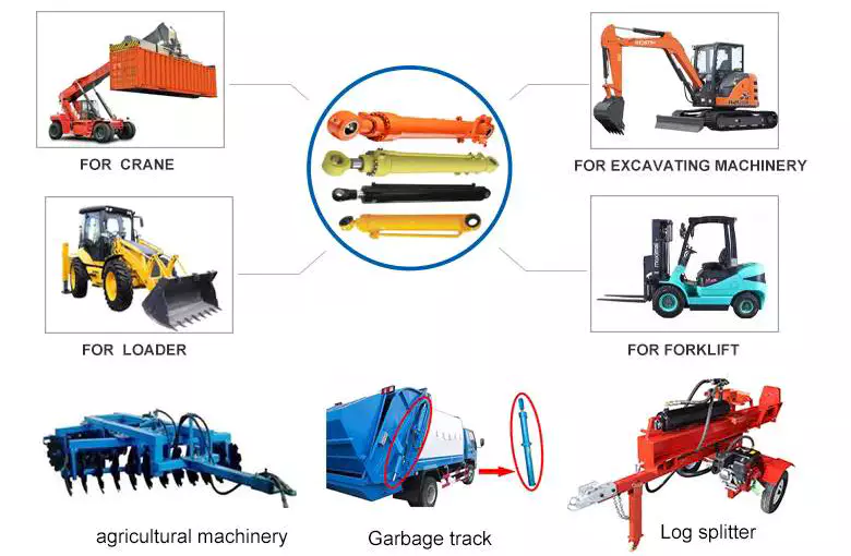
Can you provide real-world examples of machinery that heavily rely on hydraulic cylinders?
Hydraulic cylinders are widely used in various industries and applications due to their ability to provide powerful and precise linear motion. They play a crucial role in enabling the operation of heavy machinery that requires controlled force and movement. Here are some real-world examples of machinery that heavily rely on hydraulic cylinders:
1. Construction Equipment:
- Hydraulic cylinders are extensively used in construction machinery, such as excavators, bulldozers, loaders, and cranes. These machines rely on hydraulic cylinders to perform tasks like lifting heavy loads, extending and retracting booms, tilting buckets, and controlling the movement of various components. Hydraulic cylinders provide the power and precision required to handle the demanding conditions and heavy loads encountered in construction projects.
2. Agricultural Machinery:
- Many agricultural machines, including tractors, combine harvesters, and sprayers, utilize hydraulic cylinders for critical operations. Hydraulic cylinders are used to control the movement of attachments, such as front loaders, backhoes, and plows. They enable functions like lifting and lowering implements, adjusting cutting heights, and controlling the positioning of harvesting equipment. Hydraulic cylinders enhance efficiency and productivity in agricultural operations.
3. Material Handling Equipment:
- Hydraulic cylinders are integral components of material handling equipment, such as forklifts, pallet jacks, and cranes. These machines rely on hydraulic cylinders to lift and lower loads, tilt platforms or forks, and control the movement of lifting mechanisms. Hydraulic cylinders provide the necessary strength and precision to handle heavy loads and ensure safe and efficient material handling operations.
4. Industrial Machinery:
- Various industrial machinery and equipment heavily rely on hydraulic cylinders for critical functions. Examples include hydraulic presses, injection molding machines, metal-forming machines, and hydraulic-powered robots. Hydraulic cylinders enable precise control of force and movement in these applications, allowing for accurate shaping, pressing, and assembly processes.
5. Mining Equipment:
- Hydraulic cylinders are extensively used in mining machinery and equipment. Underground mining machines, such as continuous miners and longwall shearers, utilize hydraulic cylinders for cutting, shearing, and roof support operations. Surface mining equipment, including hydraulic shovels, draglines, and haul trucks, rely on hydraulic cylinders for tasks like bucket movement, boom extension, and vehicle suspension.
6. Automotive Industry:
- The automotive industry extensively utilizes hydraulic cylinders in various applications. Hydraulic cylinders are employed in vehicle suspension systems, power steering systems, convertible tops, and hydraulic brake systems. They enable smooth and controlled movement, precise steering, and efficient braking in automobiles.
7. Aerospace and Aviation:
- Hydraulic cylinders are utilized in aerospace and aviation applications, such as aircraft landing gear systems, wing flaps, and cargo handling equipment. Hydraulic cylinders provide the necessary force and control for extending and retracting landing gear, adjusting wing flaps, and operating cargo doors, ensuring safe and reliable aircraft operations.
8. Marine and Offshore Industry:
- Hydraulic cylinders are essential components in marine and offshore equipment, including ship cranes, winches, and hydraulic-powered anchor systems. They enable lifting, lowering, and positioning of heavy loads, as well as the control of various marine equipment.
These are just a few examples of machinery and industries that heavily rely on hydraulic cylinders. The versatility, power, and precise control offered by hydraulic cylinders make them indispensable in a wide range of applications, where controlled linear motion and force are essential.
What is a hydraulic cylinder and how does it function in various applications?
A hydraulic cylinder is a mechanical actuator that converts hydraulic energy into linear force and motion. It plays a critical role in various applications where controlled and powerful linear motion is required. Hydraulic cylinders are commonly used in industries such as construction, manufacturing, agriculture, and transportation. Here's a detailed explanation of what a hydraulic cylinder is and how it functions:
Definition and Components:
- A hydraulic cylinder consists of a cylindrical barrel, a piston, a piston rod, and various seals. The barrel is a hollow tube that houses the piston and allows for fluid flow. The piston divides the cylinder into two chambers: the rod side and the cap side. The piston rod extends from the piston and provides a connection point for external loads. Seals are used to prevent fluid leakage and maintain hydraulic pressure within the cylinder.
Function:
- The function of a hydraulic cylinder is to convert the pressure and flow of hydraulic fluid into linear force and motion. The hydraulic fluid, typically oil, is pressurized and directed into one of the chambers of the cylinder. As the fluid enters the chamber, it applies pressure on the piston, causing it to move in a linear direction. This linear motion of the piston is transferred to the piston rod, creating a pushing or pulling force.
Working Principle:
- The working principle of a hydraulic cylinder is based on Pascal's law, which states that pressure exerted on a fluid in a confined space is transmitted equally in all directions. In a hydraulic cylinder, when hydraulic fluid is pumped into one side of the cylinder, it creates pressure on the piston. The pressure is transmitted through the fluid to the other side of the piston, resulting in a balanced force across the piston and piston rod. This force generates linear motion in the direction determined by the fluid input.
Applications:
- Hydraulic cylinders find extensive use in a wide range of applications due to their ability to generate high forces and precise control of linear motion. Some common applications include:
1. Construction Equipment: Hydraulic cylinders are used in excavators, loaders, bulldozers, and cranes for lifting, pushing, and digging tasks.
2. Manufacturing Machinery: Hydraulic cylinders are employed in presses, machine tools, and material handling equipment for pressing, clamping, and lifting operations.
3. Agricultural Machinery: Hydraulic cylinders are used in tractors, harvesters, and irrigation systems for tasks like steering, lifting, and controlling attachments.
4. Transportation: Hydraulic cylinders are utilized in vehicles such as dump trucks, garbage trucks, and forklifts for tilting, lifting, and tipping operations.
5. Aerospace and Defense: Hydraulic cylinders are employed in aircraft landing gear, missile systems, and hydraulic actuators for control surfaces.
6. Marine and Offshore: Hydraulic cylinders are used in ship steering systems, cranes, and offshore drilling equipment for various lifting and positioning tasks.
In these applications, hydraulic cylinders offer advantages such as high force capability, precise control, compact size, and durability. They provide efficient and reliable linear motion, contributing to enhanced productivity and functionality in a wide range of industries.
Overall, hydraulic cylinders are integral components in various applications where controlled and powerful linear motion is required. Their ability to convert hydraulic energy into mechanical force makes them invaluable in numerous industries, enabling the operation of heavy machinery, precise positioning, and efficient load handling.
editor by CX 2023-12-01
China manufacturer CZPT Excavator Ex60-1 Boom Arm/Stick Bucket Hydraulic Cylinder with Free Design Custom
Product Description
Hydraulic Cylinders for Earth Moving Machinery
Machine workshop
- product view
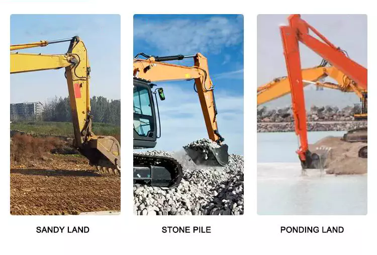
Hydraulic cylinders that are used on construction equipment must be rugged and reliable. They will experience a lifetime exposed to heavy use in a harsh environment. Failure in service will result in costly downtime, project delays and maintenance headaches.
These cylinders must be designed to withstand the following:
Temperature Extremes -winter cold and summer heat.
Abrasives - dirt, CZPT and dust.
Corrosive Environments - rain and salt.
Work Load - heavy continual use.
Contamination - asphalt and cement splatter.
- Technology
| Hydraulic Cylinder Tube: Using imported equipment rolling machine | |||
| Kind of steel | 45# | Tensile strength N/mm | ≥647 |
| Linearity | 0.3-1/1000 | Specific elongation | ≥4 |
| Precision of size | HB | ||
| Roughness of inner hole | 0.4-0.8 | ||
| Piston rod: Adopt high precision mirror polishing | |
| Material | 45# high grade carbon steel or 40CR |
| Tempering hardness | HB240-260 |
| The depth of the high frequency | 2mm-3mm |
| High frequency hardness | HRC55°±2° |
| Chrome plating thickness | 0.03mm-0.06mm |
| Chromium layer hardness | HV800-1000vpn |
| Straightness | ≤0.08mm/m |
| Surface roughness | Ra0.03um- Ra0.06um |
| Outside diameter tolerance | f7 |
CMM INSPECTION ON SITE
- Advanced Equipment
*Skive Roller Burnishing Machines
*Vertical Honing machine
*Mchining Centers
*CNC Lathes
*Automatic Welding Machines
*Grinders
*Polishing machine
*Cylinder Assembly Benches
*Cylinder Test Benches
*Spray room
- Process flow
Materials feeling → Tempering → Cylindrical lathe cutting → High-frequency quenching → Cylindrical grinding → Hard chrome plating → External grinding
After tempering and surface high-frequency quenching,external surface hard chrome
painting, make it hard both internal and external with smooth surface.
- Service
Tooling warehouse
Customer visit:
Warehouse
- FAQ:
Q1:How about the quality?
A:Third party inspections are always welcomed. Like BV, SGS etc.
Q2: How long is the delivery time?
A: Generally about 5-10 days if the goods in stock. Or will be 15-20 days if the goods are not in stock. And also according to the quantity.
Q3:May I customize the steel pipe?
A:Sure you can, we can produce according to your requirement, you can send the CAD or design drawing.
Q4:Any value-added Services?
A: Fortunately for you,we are very experience in this industry. We have equipped our warehouse with the necessities to perform in-house painting,coating,pipe cutting, etc.
Q5: How about the trade terms?
A: EXW, FOB, CFR, CIF, LC will be accepted.
Drive shaft type
The driveshaft transfers torque from the engine to the wheels and is responsible for the smooth running of the vehicle. Its design had to compensate for differences in length and angle. It must also ensure perfect synchronization between its joints. The drive shaft should be made of high-grade materials to achieve the best balance of stiffness and elasticity. There are 3 main types of drive shafts. These include: end yokes, tube yokes and tapered shafts.
tube yoke
Tube yokes are shaft assemblies that use metallic materials as the main structural component. The yoke includes a uniform, substantially uniform wall thickness, a first end and an axially extending second end. The first diameter of the drive shaft is greater than the second diameter, and the yoke further includes a pair of opposing lugs extending from the second end. These lugs have holes at the ends for attaching the axle to the vehicle.
By retrofitting the driveshaft tube end into a tube fork with seat. This valve seat transmits torque to the driveshaft tube. The fillet weld 28 enhances the torque transfer capability of the tube yoke. The yoke is usually made of aluminum alloy or metal material. It is also used to connect the drive shaft to the yoke. Various designs are possible.
The QU40866 tube yoke is used with an external snap ring type universal joint. It has a cup diameter of 1-3/16" and an overall width of 4½". U-bolt kits are another option. It has threaded legs and locks to help secure the yoke to the drive shaft. Some performance cars and off-road vehicles use U-bolts. Yokes must be machined to accept U-bolts, and U-bolt kits are often the preferred accessory.
The end yoke is the mechanical part that connects the drive shaft to the stub shaft. These yokes are usually designed for specific drivetrain components and can be customized to your needs. Pat's drivetrain offers OEM replacement and custom flanged yokes.
If your tractor uses PTO components, the cross and bearing kit is the perfect tool to make the connection. Additionally, cross and bearing kits help you match the correct yoke to the shaft. When choosing a yoke, be sure to measure the outside diameter of the U-joint cap and the inside diameter of the yoke ears. After taking the measurements, consult the cross and bearing identification drawings to make sure they match.
While tube yokes are usually easy to replace, the best results come from a qualified machine shop. Dedicated driveshaft specialists can assemble and balance finished driveshafts. If you are unsure of a particular aspect, please refer to the TM3000 Driveshaft and Cardan Joint Service Manual for more information. You can also consult an excerpt from the TSB3510 manual for information on angle, vibration and runout.
The sliding fork is another important part of the drive shaft. It can bend over rough terrain, allowing the U-joint to keep spinning in tougher conditions. If the slip yoke fails, you will not be able to drive and will clang. You need to replace it as soon as possible to avoid any dangerous driving conditions. So if you notice any dings, be sure to check the yoke.
If you detect any vibrations, the drivetrain may need adjustment. It's a simple process. First, rotate the driveshaft until you find the correct alignment between the tube yoke and the sliding yoke of the rear differential. If there is no noticeable vibration, you can wait for a while to resolve the problem. Keep in mind that it may be convenient to postpone repairs temporarily, but it may cause bigger problems later.
end yoke
If your driveshaft requires a new end yoke, CZPT has several drivetrain options. Our automotive end yoke inventory includes keyed and non-keyed options. If you need tapered or straight holes, we can also make them for you.
A U-bolt is an industrial fastener that has U-shaped threads on its legs. They are often used to join 2 heads back to back. These are convenient options to help keep drivetrain components in place when driving over rough terrain, and are generally compatible with a variety of models. U-bolts require a specially machined yoke to accept them, so be sure to order the correct size.
The sliding fork helps transfer power from the transfer case to the driveshaft. They slide in and out of the transfer case, allowing the u-joint to rotate. Sliding yokes or "slips" can be purchased separately. Whether you need a new 1 or just a few components to upgrade your driveshaft, 4 CZPT Parts will have the parts you need to repair your vehicle.
The end yoke is a necessary part of the drive shaft. It connects the drive train and the mating flange. They are also used in auxiliary power equipment. CZPT's drivetrains are stocked with a variety of flanged yokes for OEM applications and custom builds. You can also find flanged yokes for constant velocity joints in our extensive inventory. If you don't want to modify your existing drivetrain, we can even make a custom yoke for you.


China best Boom Hydraulic Cylinder for R220-9s Excavator, 31q6-50110 with Best Sales
Product Description
| Product Name | HYUNDAI hydraulic boom/arm/bucket oil cylinder for sale | ||
| Material | stainless steel | ||
| Application | construction industry machinery | ||
Shipping and Packing:
| Shipping Mode: | By air, by sea ,by express (DHL,Fedex, ,etc.) |
| Standard Shipping Time: | By air within 5-6 days. By DHL: within 4-5days.by sea about 1 month |
| Standard Packing: | Carton or wooden case |
| Special Packing: | We can discuss and support you. |
General Order Process:
*Step1: Contact us by online, Email , ,WhatsApp
*Step2: We discuss prices, lead time, payment terms, shipping mode, packing.
*Step3: Issuing PI for you and you confirm .
*Step4: Arrange payment
*Step5: Delivery
*Step6: Goods reach you.
*Step7: After-sale service special for you.
All kinds of excavator parts we can supply as follow:
1 Hydraulic parts: hydraulic pump, main valve, hydraulic cylinder, final drive, travel motor, swing motor etc.
2 Engine parts: engine ass'y, piston, piston ring, cylinder block, cylinder head, crankshaft, turbocharger,
fuel injection pump, starting motor and alternator etc.
3 Undercarriage part: Track roller, Carrier roller, Track Link, Track shoe, Sprocket, Idler and Idler cushion etc.
The benefits of using pulleys
A pulley is a mechanical device that converts force into rotation. There are many advantages to using pulleys. Let's take a look at a few of them. This article will describe the advantages, types, applications, and power sources of pulleys. You can then choose the pulley that best suits your specific needs. If you're looking for a new tool to help you with a certain task, this article is for you.
Mechanical advantage
The mechanical advantage of a pulley can be defined as the ratio of applied force to the applied force. The mechanical advantage of a pulley can be calculated by considering several factors, including weight and friction. It can be calculated by the force applied per unit length of rope and the number of pulleys used. In a single-circuit system, the force required to lift a heavy object is equal to the user's body weight.
The mechanical advantage of a pulley can be realized by comparing it to a seesaw. Both uses of rope are suitable for lifting objects. A rope 4 times heavier than a kilo is 4 times as effective. Because the forces on both sides of the pulley are equal, a small force is enough to move a large weight a short distance. The same force can be applied to a large mass to lift it several meters.
After introducing the concept of mechanical advantage, learners will practice using the pulley system. In addition to testing the pulley system, they should also calculate its mechanical advantage. Using either the instructor-provided handout or the learner's workbook, students will determine how easily the pulley system functions. Once they have completed the test, they can discuss their results and how the system can be improved. These courses are best completed as part of a mini-unit or as a standalone main course.
The mechanical advantage of the pulley system is proportional to the number of rope loops. This circuit requires the same force as the dual circuit to lift heavy objects. A single lap requires only a third of the force to lift a double lap, while 3 laps require almost half the energy required for a single lap. The mechanical advantage of the pulley system becomes constant as the number of cycles increases.
The 3:1 Mechanical Advantage system feels like lifting a 300-pound load with 3 feet of rope. The three-foot-long rope moves the load 1 foot high. Understanding the mechanical advantages of pulleys is critical for rescuers when trying to create the perfect pulley system. Ideally, the pulley system will be anchored to a nearby rock, tree, pole or person - if the weight is not too heavy.
Types of pulleys
There are several types of pulleys. V-belt pulleys are the type commonly used in vehicles and electric motors. "V" pulleys require a "V" belt, and some even have multiple V grooves. "V" pulleys are often used in heavy duty applications for power transmission because they reduce the risk of power slippage.
Composite pulleys combine the properties of fixed and movable pulleys. Compound pulleys are able to change the direction of force while requiring relatively low force to move even the heaviest loads. Mechanical advantage is a measure of the effectiveness of a machine or equipment. It can be divided into 3 categories: force, distance and mechanics. Once you understand how each type works, you can design complex machines.
Fixed pulleys: These pulleys are the most basic type of pulleys. They use ropes and slotted wheels to move with the lifted object. Because they are so simple to set up, lifting heavy objects is a breeze. Although the moving object feels light, it is actually heavier than it actually is. These pulleys are used in construction cranes, utility elevators and many different industries.
Compound Pulley System: A pulley pulley is a combination of 2 fixed pulleys and 1 movable pulley. Compound pulley systems are effective for moving heavy objects because they have the largest force multipliers and are flexible enough to change the direction of the force as needed. Composite pulley systems are commonly used in rock climbing, theater curtains and sailing. If you're looking for a pulley system, you can start by evaluating the types of pulleys and their uses.
Construction Pulleys: These are the most basic types of pulleys and have wheel rails. These pulleys can be lifted to great heights and attached to chains or ropes. They allow workers to access equipment or materials from greater heights. They are usually mounted on wheels with axles and secured with ropes. They are essential tools for construction workers. There are many different types of pulleys out there.
energy source
Belts and pulleys are mechanical devices used to transmit energy and rotational motion. The belt is connected to the rotating part of the energy source, and the pulley is mounted on the other. One pulley transmits power to the other, while the other changes the direction of the force. Many devices use this combination, including automobiles, stationary generators, and winches. It is used in many home applications, from conveyors to treadmills. Pulleys are also used for curtains in theater halls.
Pulley systems are an essential part of modern industry and everyday life. Pulleys are used in elevators, construction sites and fitness equipment. They are also used in belt-driven generators as backup power. Despite their simple and seemingly humble beginnings, they have become a versatile tool. From lifting heavy objects to guiding wind turbines, pulley systems are widely used in our daily lives.
The main reason why pulleys are so popular is the mechanical advantage they offer. They can lift a lot of weight by applying very little force over longer distances. For example, a small motor can pull 10 meters of cable, while a large motor can pull 1 meter. Also, the work done is equal to the force times the distance traveled, so the energy delivered to the large motor is the same.
The power source for the pulley system can be cables, belts or ropes. The drive element in a pulley system is usually a rope or cable. A belt is a loop of flexible material that transmits motion from 1 pulley to another. The belt is attached to the shaft and a groove is cut in the pulley. The belt then transfers energy from 1 pulley to the other through the system.
application
A pulley is a mechanical device used to lift heavy objects. They reduce the amount of work required to lift heavy objects and are an excellent choice for many applications. There are several different applications for pulleys, including elevators, grinders, planters, ladder extensions, and mountaineering or rock climbing. Let's take a look at some of the most popular uses for pulleys in modern society. These include:-
A pulley is a mechanical device that changes force. To use, you wrap the rope around it and pull down to lift the object. While this device is very useful, a major limitation of using pulleys is that you still have to apply the same force to lift the object as you would without the pulleys. This is why people use pulleys to move large objects like furniture and cars.
In addition to lifting heavy objects, pulleys are used in elevators, flagpoles and wells. These systems allow people to move heavy objects without straining their backs. Many other examples of pulleys in the home include garage doors, flagpoles, and elevators. They also help raise and lower flagpoles, which can reach several stories high.
There are 2 basic types of pulleys: movable and fixed. Fixed pulleys are attached to a ceiling or other object using 2 ropes. Modern elevators and construction cranes use movable pulleys, as do some weight machines in gyms. Composite pulleys combine movable and fixed pulleys to minimize the force required to move heavy objects.
Another type of fixed pulley is the flagpole. A flagpole can support a country, organization, or anything else that needs to be lifted. A taller flagpole creates a prouder moment for those who support it. The operation of the rope and pulley mechanism is very simple. The user simply attaches the flag to the rope, pulls the pulley, and he or she can watch the flag rise and unfold.
China Good quality CZPT Excavator Dedicated Boom Arm Bucket Cylinder Excavator Hydraulic Cylinder with Good quality
Product Description
| Product name | hydraulic cylinder |
| Type | excavator hydraulic cylinder |
| Color | Black/gray/red |
| Brand Name | BRZ |
| Model Number | See details |
| Feature | 1. Long life. 2. High strength. 3. Easier for maintenance 4. More accurate. 5. Anti-corrosion. 6. Suitable for various environments. |
| Product Description | The excavator hydraulic cylinder is divided into a boom cylinder, a forearm cylinder and a bucket cylinder, which is the executive system of the excavator. Follow the instructions of the operator to complete various actions. |
We can supply you all kinds of excavator spare parts as following:
1 Hydraulic parts: hydraulic pump, main control valve, hydraulic cylinder, final drive, travel motor, swing
motor,gear box, slewing bearing etc.
2 Engine parts: engine ass'y, piston, piston ring, cylinder block, cylinder head, crankshaft, turbocharger,
fuel injection pump, starting motor and alternator etc.
3 Undercarriage parts: Track roller, Carrier roller, Track Link, Track shoe, Sprocket, Idler and Idler cushion
,coil adjuster,rubber track and pad etc.
4 Cab parts: operator's cab assy, wiring harness, monitor, controller, seat, door etc.
HangZhou CZPT Electrical Equipment Co., Ltd. Our main products include a variety of well-known
brands of excavators, bulldozers, loaders, forklifts, wheel loaders, as well as a variety of bulldozers,
excavators, structural and chassis components, hydraulic pumps, hydraulic motors, final drive, travel
motor , rotary motor assembly, engine parts and so on. Our company has established a mature sales
system and improve the service network. We have gained a timely supply at home and abroad between
good reputation and excellent customer service.According to customer support, the company has made
great achievements. To become a leading Chinese construction machinery industry. "Honesty, pragmatism,
hard work, innovation" business philosophy, I always provide quality products to customers, providing
first-class, quick and thoughtful service.We will strive to become an advanced enterprise in the industry,
reached the international level, we will continue to forge ahead, innovation, and establish a century enterprise.
FAQ
Q: How to guarantee the same?
A: Before sending, I will take pictures. After confirmation, I send.
Q: When to ship?
A: Once getting payment then arrange.
Q: Import customs fee?
A: It depends on import country. I can make lower valve so that you can pay lower customs fee even no need to pay.
Q: How long for transport?
A: For express/ air, it takes about 5 days. For land/ sea, it takes about 1 month. It depeds on your address.
Q: Product usage?
A: If any problem about usage, I will solve at first time.
What is a bushing?
A bushing is a cylindrical lining made of a flexible material inside a metal housing. The inner squeeze tube of the bushing helps prevent it from being squeezed by the clip. The material also reduces friction and isolates vibration and noise, while improving performance. This article discusses some of the most common uses for bushings. In this article, we'll discuss the most important reasons to choose a bushing for your transmission.
DESCRIPTION Anti-friction cylindrical lining
A bushing is a bearing that minimizes friction and wear within the bore. It is also used as a housing for shafts, pins, hinges or other types of objects. It takes its name from the Middle Dutch word shrub, which means "box". It is also homologous to the second element of blunderbuss. Here's how to identify bushings and how to use them.
Vibration isolation
Vibration mounts are required for inertial guidance and navigation systems, radar components, and engine accessories. Bushings isolate vibration and provide a more robust design in these applications. Bushings help eliminate vibration-related operational challenges and help protect expensive equipment from damage. Below are several types of vibrating mounts and the differences between them. Each type has unique uses and applications, and the type you choose will depend on the nature of the components and the environment.
Vibration isolation is an important safety feature of many modern machines and instruments. Used to reduce the dynamic consumption that an object suffers at runtime. Instead, it protects equipment and structures from amplitude-related damage. Bushings insulate objects from vibration by reducing the amount of dynamic action transferred from the object to the support structure. Bushings are a popular choice for vibration equipment manufacturers.
Vibration isolation is important in many industrial applications. Vibration can wreak havoc on electronic and mechanical equipment. The forces exerted by vibration can reduce the life expectancy of equipment, leading to premature failure. The cost of isolation depends on the weight of the object being isolated. Most isolators have minimum damping in the isolation region and maximum damping at natural frequencies. In addition, the cost of installation, transportation and maintenance is usually included in the cost.
In addition to providing shock and vibration isolation, bushings help stabilize components by absorbing shock. These devices may need to be replaced in the long run, and your machine design may dictate whether you need to buy more than one. Bushings are an important part of your equipment, so don't skimp on quality when choosing a vibration isolation mount. You won't regret it. They won't break your budget, but will keep your equipment safe.
reduce noise
A properly positioned tree will block the view between the noise source and your house. Make sure the tree is taller than your house to effectively reduce noise. Also, make sure the sprocket and axle are properly aligned. The less noise they make, the better. If you have a noisy neighbor, you may want to consider installing a bushing at the front of the house to block the noise.
While it's possible to replace the bushing yourself, it's best to make sure you follow some basic procedures first. Park your car on level ground and apply the brakes before removing the hood. Check that the wheels move freely. Remember to wear gloves and goggles, and don't cut yourself with sharp objects when changing bushings. If you can't see under the hood, try opening the hood to allow more light to reach the engine area.
SuperPro bushings are designed to reduce noise and vibration in the automotive industry. They are a popular choice for aftermarket bushing manufacturers. While OE rubber bushings are soft and quiet, these polyurethane bushings are specifically designed to eliminate these noise issues. By determining the diameter of your vehicle's anti-roll bars, you can choose the right bushing for your vehicle. You'll be glad you did!
Damaged bushings can cause the stabilizer bar to become unstable. This, in turn, can cause the steering components to misalign, creating a loud ding. Worn bushings can also cause the wheel to squeak as it moves. If they're worn, you'll hear squeaks when cornering. You may even hear these noises when you are turning or changing lanes.
a bearing
A bushing is a component that provides a bearing surface for the forces acting axially on the shaft. A typical example of a thrust bearing is a propeller shaft. The bushing can be a separate part or an integral part of the machine. Typically, bushings are replaceable, while integral bearings are permanent and should not be replaced unless worn or damaged. Bushings are most commonly used in machinery, where they allow relative movement between components.
The bushing is usually an integral unit, while the bearing may have several parts. Simple bushings can be made of brass, bronze or steel. It is often integrated into precision machined parts and helps reduce friction and wear. Typically, bushings are made of brass or bronze, but other materials can also be used. Different designs have different applications, so you should understand what your application requires before purchasing a sleeve.
The most common uses of plain bearings are in critical applications, including turbines and compressors. They are also commonly used in low-speed shafting, including propeller shafts and rudders. These bearings are very economical and suitable for intermittent and linear motion. However, if your application does not require continuous lubrication, a plain bearing may not be required.
Another popular use for sleeves is in food processing. These bearings can be made from a variety of materials, including stainless steel and plastic. Plastic bearings are more cost-effective than metal and are an excellent choice for high-speed applications. These materials are also resistant to corrosion and wear. However, despite their high cost, they can be made from a variety of materials. However, in most cases, the materials used for plain bearings are aluminum nickel, phosphorus and silicon.
China supplier CZPT Excavator Dedicated Boom Arm Bucket Cylinder Excavator Hydraulic Cylinder near me supplier
Product Description
| Product name | hydraulic cylinder |
| Type | excavator hydraulic cylinder |
| Color | Black/gray/red |
| Brand Name | BRZ |
| Model Number | See details |
| Feature | 1. Long life. 2. High strength. 3. Easier for maintenance 4. More accurate. 5. Anti-corrosion. 6. Suitable for various environments. |
| Product Description | The excavator hydraulic cylinder is divided into a boom cylinder, a forearm cylinder and a bucket cylinder, which is the executive system of the excavator. Follow the instructions of the operator to complete various actions. |
We can supply you all kinds of excavator spare parts as following:
1 Hydraulic parts: hydraulic pump, main control valve, hydraulic cylinder, final drive, travel motor, swing
motor,gear box, slewing bearing etc.
2 Engine parts: engine ass'y, piston, piston ring, cylinder block, cylinder head, crankshaft, turbocharger,
fuel injection pump, starting motor and alternator etc.
3 Undercarriage parts: Track roller, Carrier roller, Track Link, Track shoe, Sprocket, Idler and Idler cushion
,coil adjuster,rubber track and pad etc.
4 Cab parts: operator's cab assy, wiring harness, monitor, controller, seat, door etc.
HangZhou CZPT Electrical Equipment Co., Ltd. Our main products include a variety of well-known
brands of excavators, bulldozers, loaders, forklifts, wheel loaders, as well as a variety of bulldozers,
excavators, structural and chassis components, hydraulic pumps, hydraulic motors, final drive, travel
motor , rotary motor assembly, engine parts and so on. Our company has established a mature sales
system and improve the service network. We have gained a timely supply at home and abroad between
good reputation and excellent customer service.According to customer support, the company has made
great achievements. To become a leading Chinese construction machinery industry. "Honesty, pragmatism,
hard work, innovation" business philosophy, I always provide quality products to customers, providing
first-class, quick and thoughtful service.We will strive to become an advanced enterprise in the industry,
reached the international level, we will continue to forge ahead, innovation, and establish a century enterprise.
FAQ
Q: How to guarantee the same?
A: Before sending, I will take pictures. After confirmation, I send.
Q: When to ship?
A: Once getting payment then arrange.
Q: Import customs fee?
A: It depends on import country. I can make lower valve so that you can pay lower customs fee even no need to pay.
Q: How long for transport?
A: For express/ air, it takes about 5 days. For land/ sea, it takes about 1 month. It depeds on your address.
Q: Product usage?
A: If any problem about usage, I will solve at first time.
What Are Screw Shaft Threads?
A screw shaft is a threaded part used to fasten other components. The threads on a screw shaft are often described by their Coefficient of Friction, which describes how much friction is present between the mating surfaces. This article discusses these characteristics as well as the Material and Helix angle. You'll have a better understanding of your screw shaft's threads after reading this article. Here are some examples. Once you understand these details, you'll be able to select the best screw nut for your needs.
Coefficient of friction between the mating surfaces of a nut and a screw shaft
There are 2 types of friction coefficients. Dynamic friction and static friction. The latter refers to the amount of friction a nut has to resist an opposing motion. In addition to the material strength, a higher coefficient of friction can cause stick-slip. This can lead to intermittent running behavior and loud squeaking. Stick-slip may lead to a malfunctioning plain bearing. Rough shafts can be used to improve this condition.
The 2 types of friction coefficients are related to the applied force. When applying force, the applied force must equal the nut's pitch diameter. When the screw shaft is tightened, the force may be removed. In the case of a loosening clamp, the applied force is smaller than the bolt's pitch diameter. Therefore, the higher the property class of the bolt, the lower the coefficient of friction.
In most cases, the screwface coefficient of friction is lower than the nut face. This is because of zinc plating on the joint surface. Moreover, power screws are commonly used in the aerospace industry. Whether or not they are power screws, they are typically made of carbon steel, alloy steel, or stainless steel. They are often used in conjunction with bronze or plastic nuts, which are preferred in higher-duty applications. These screws often require no holding brakes and are extremely easy to use in many applications.
The coefficient of friction between the mating surfaces of t-screws is highly dependent on the material of the screw and the nut. For example, screws with internal lubricated plastic nuts use bearing-grade bronze nuts. These nuts are usually used on carbon steel screws, but can be used with stainless steel screws. In addition to this, they are easy to clean.
Helix angle
In most applications, the helix angle of a screw shaft is an important factor for torque calculation. There are 2 types of helix angle: right and left hand. The right hand screw is usually smaller than the left hand one. The left hand screw is larger than the right hand screw. However, there are some exceptions to the rule. A left hand screw may have a greater helix angle than a right hand screw.
A screw's helix angle is the angle formed by the helix and the axial line. Although the helix angle is not usually changed, it can have a significant effect on the processing of the screw and the amount of material conveyed. These changes are more common in 2 stage and special mixing screws, and metering screws. These measurements are crucial for determining the helix angle. In most cases, the lead angle is the correct angle when the screw shaft has the right helix angle.
High helix screws have large leads, sometimes up to 6 times the screw diameter. These screws reduce the screw diameter, mass, and inertia, allowing for higher speed and precision. High helix screws are also low-rotation, so they minimize vibrations and audible noises. But the right helix angle is important in any application. You must carefully choose the right type of screw for the job at hand.
If you choose a screw gear that has a helix angle other than parallel, you should select a thrust bearing with a correspondingly large center distance. In the case of a screw gear, a 45-degree helix angle is most common. A helix angle greater than zero degrees is also acceptable. Mixing up helix angles is beneficial because it allows for a variety of center distances and unique applications.
Thread angle
The thread angle of a screw shaft is measured from the base of the head of the screw to the top of the screw's thread. In America, the standard screw thread angle is 60 degrees. The standard thread angle was not widely adopted until the early twentieth century. A committee was established by the Franklin Institute in 1864 to study screw threads. The committee recommended the Sellers thread, which was modified into the United States Standard Thread. The standardized thread was adopted by the United States Navy in 1868 and was recommended for construction by the Master Car Builders' Association in 1871.
Generally speaking, the major diameter of a screw's threads is the outside diameter. The major diameter of a nut is not directly measured, but can be determined with go/no-go gauges. It is necessary to understand the major and minor diameters in relation to each other in order to determine a screw's thread angle. Once this is known, the next step is to determine how much of a pitch is necessary to ensure a screw's proper function.
Helix angle and thread angle are 2 different types of angles that affect screw efficiency. For a lead screw, the helix angle is the angle between the helix of the thread and the line perpendicular to the axis of rotation. A lead screw has a greater helix angle than a helical one, but has higher frictional losses. A high-quality lead screw requires a higher torque to rotate. Thread angle and lead angle are complementary angles, but each screw has its own specific advantages.
Screw pitch and TPI have little to do with tolerances, craftsmanship, quality, or cost, but rather the size of a screw's thread relative to its diameter. Compared to a standard screw, the fine and coarse threads are easier to tighten. The coarser thread is deeper, which results in lower torques. If a screw fails because of torsional shear, it is likely to be a result of a small minor diameter.
Material
Screws have a variety of different sizes, shapes, and materials. They are typically machined on CNC machines and lathes. Each type is used for different purposes. The size and material of a screw shaft are influenced by how it will be used. The following sections give an overview of the main types of screw shafts. Each 1 is designed to perform a specific function. If you have questions about a specific type, contact your local machine shop.
Lead screws are cheaper than ball screws and are used in light-duty, intermittent applications. Lead screws, however, have poor efficiency and are not recommended for continuous power transmission. But, they are effective in vertical applications and are more compact. Lead screws are typically used as a kinematic pair with a ball screw. Some types of lead screws also have self-locking properties. Because they have a low coefficient of friction, they have a compact design and very few parts.
Screws are made of a variety of metals and alloys. Steel is an economical and durable material, but there are also alloy steel and stainless steel types. Bronze nuts are the most common and are often used in higher-duty applications. Plastic nuts provide low-friction, which helps reduce the drive torques. Stainless steel screws are also used in high-performance applications, and may be made of titanium. The materials used to create screw shafts vary, but they all have their specific functions.
Screws are used in a wide range of applications, from industrial and consumer products to transportation equipment. They are used in many different industries, and the materials they're made of can determine their life. The life of a screw depends on the load that it bears, the design of its internal structure, lubrication, and machining processes. When choosing screw assemblies, look for a screw made from the highest quality steels possible. Usually, the materials are very clean, so they're a great choice for a screw. However, the presence of imperfections may cause a normal fatigue failure.
Self-locking features
Screws are known to be self-locking by nature. The mechanism for this feature is based on several factors, such as the pitch angle of the threads, material pairing, lubrication, and heating. This feature is only possible if the shaft is subjected to conditions that are not likely to cause the threads to loosen on their own. The self-locking ability of a screw depends on several factors, including the pitch angle of the thread flank and the coefficient of sliding friction between the 2 materials.
One of the most common uses of screws is in a screw top container lid, corkscrew, threaded pipe joint, vise, C-clamp, and screw jack. Other applications of screw shafts include transferring power, but these are often intermittent and low-power operations. Screws are also used to move material in Archimedes' screw, auger earth drill, screw conveyor, and micrometer.
A common self-locking feature for a screw is the presence of a lead screw. A screw with a low PV value is safe to operate, but a screw with high PV will need a lower rotation speed. Another example is a self-locking screw that does not require lubrication. The PV value is also dependent on the material of the screw's construction, as well as its lubrication conditions. Finally, a screw's end fixity - the way the screw is supported - affects the performance and efficiency of a screw.
Lead screws are less expensive and easier to manufacture. They are a good choice for light-weight and intermittent applications. These screws also have self-locking capabilities. They can be self-tightened and require less torque for driving than other types. The advantage of lead screws is their small size and minimal number of parts. They are highly efficient in vertical and intermittent applications. They are not as accurate as lead screws and often have backlash, which is caused by insufficient threads.
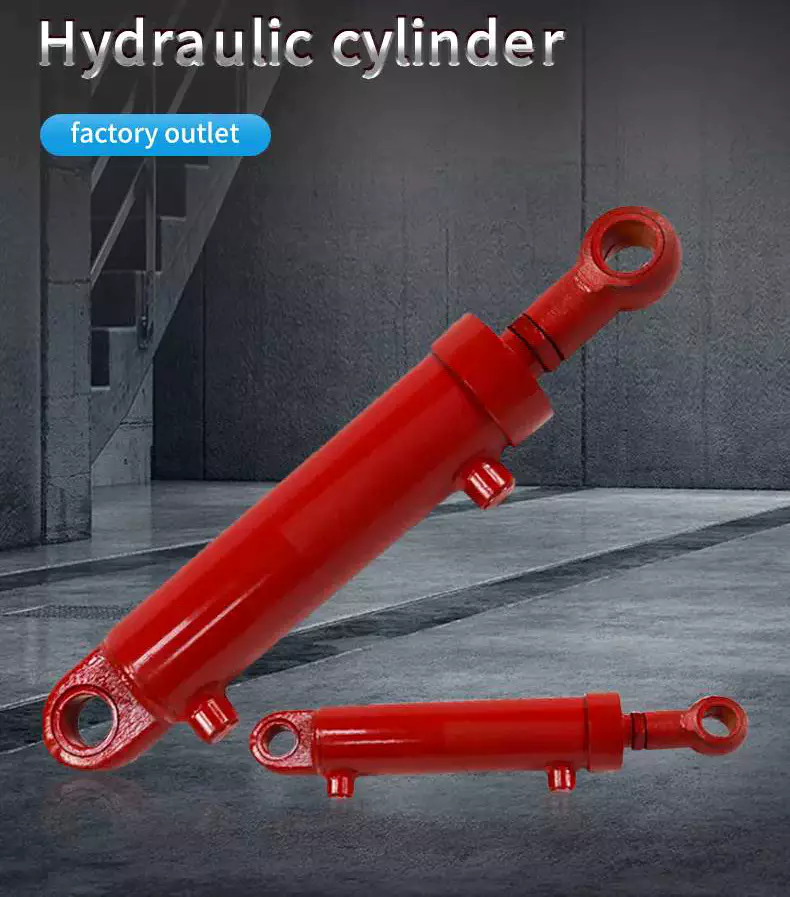
China OEM High Precision Double Action Hydraulic Cylinder for Boom Cylinder wholesaler
Product Description
Product Description
Quick details
Gland ----High grade ductile iron
Tube -----Cold drawn honed tubling
Piston-----High grade ductile iron
Piston rod----Chromed C45
Piston seal----Urethane seal
End cap----Casting seel
Mounting style----Pins and clips included
Gland seals----Polyurethane U-cup
Rod wiper----Urethane snap in
Paint color----Semi-gloss black, grey, red
1.Light-weight,high strength
Base on the nature of construction work,the hydraulic cylinders need to suit for high strength,high
using frequency,high fatigability.to promise the sability and reliablity of application.
2.the seal system
select the excellent seal kits from japan and germany.adopt the advanced physical design,make
sure the hydraulic cylinder get the best piston rod oil film
3.cylinder body
adopt the good-quality alloy honed tube,though cold-drawing and rolling,to reach an excellent
toughness and surface hardness.improve the wear-resistance.
4.piston rod
middle frequency induction hardening and tempering,chrome plated on rod surface to improve the
anti-rust ,wear-resistance and anti-scratch property.
5.safety/cushioning fuction
The inside of cylinder set up an cushioning device in the end of stroke,it can absorb the juge inpact.
Technical Specification size.
|
cylinder diameter (mm) |
piston rod diameter (mm) |
max stroke (mm) |
||
|
40 |
20 |
22 |
25 |
500 |
|
50 |
25 |
28 |
32 |
600 |
|
63 |
32 |
35 |
45 |
800 |
|
80 |
40 |
45 |
55 |
2000 |
|
90 |
45 |
50 |
63 |
2000 |
|
100 |
50 |
55 |
70 |
4000 |
|
110 |
55 |
63 |
80 |
4000 |
|
125 |
63 |
70 |
90 |
4000 |
|
140 |
70 |
80 |
100 |
4000 |
|
150 |
75 |
85 |
105 |
4000 |
|
160 |
80 |
90 |
110 |
4000 |
|
180 |
90 |
100 |
125 |
4000 |
|
200 |
100 |
110 |
140 |
4000 |
|
220 |
110 |
125 |
160 |
4000 |
|
250 |
125 |
140 |
180 |
4000 |
Cylinder tube machining
Piston
Application boom cylider, stick cylinder, Dozer cylinder.
| Excavator Type | Name | Stroke (mm) | Installation Diameter(mm) | Cylinder Diameter(mm) | Rod Diameter(mm) |
| 5.5T | Boom Cylinder | 710 | 1120 | 115 | 65 |
| Stick Cylinder | 815 | 1210 | 90 | 55 | |
| Bucket Cylinder | 605 | 945 | 85 | 55 | |
| Dozer Cylinder | 150 | 500 | 110 | 60 | |
| 6.5T | Boom Cylinder | 885 | 1311 | 110 | 65 |
| Stick Cylinder | 900 | 1300 | 90 | 60 | |
| Bucket Cylinder | 730 | 1120 | 80 | 50 | |
| Dozer Cylinder | 145 | 565 | 130 | 70 | |
| 11.5T | Left Boom Cylinder | 980 | 1480 | 100 | 70 |
| Right Boom Cylinder | 980 | 1480 | 100 | 70 | |
| Stick Cylinder | 1571 | 1530 | 115 | 80 | |
| Bucket Cylinder | 885 | 1375 | 95 | 65 | |
| 18.5T | Left Boom Cylinder | 1195 | 1790 | 120 | 85 |
| Right Boom Cylinder | 1195 | 1790 | 120 | 85 | |
| Stick Cylinder | 1405 | 2000 | 130 | 95 | |
| Bucket Cylinder | 1110 | 1630 | 110 | 80 | |
| 20T | Boom Cylinder | 1285 | 1870 | 120 | 85 |
| Stick Cylinder | 1490 | 2075 | 135 | 95 | |
| Bucket Cylinder | 1120 | 1680 | 115 | 80 | |
| 23T | Boom Cylinder Assembly | 1295 | 1870 | 130 | 90 |
| Stick Cylinder Assembly | 1675 | 2225 | 140 | 100 | |
| Bucket Cylinder Assembly | 1156 | 1744 | 130 | 90 | |
| 26T | Boom Cylinder Assembly | 1420 | 1980 | 139 | 100 |
| Stick Cylinder Assembly | 1748 | 2348 | 149 | 110 | |
| Bucket Cylinder Assembly | 1130 | 1753 | 134 | 100 | |
| 40T | Boom Cylinder Assembly | 1495 | 2135 | 160 | 110 |
| Stick Cylinder Assembly | 1790 | 2480 | 170 | 110 | |
| Bucket Cylinder Assembly | 1285 | 1990 | 160 | 110 |
Q: Are you trading company or manufacturer ?
A: We are factory.
Q: How long is your delivery time?
A: Generally it is 5-10 days if the goods are in stock. or it is 15-20 days if the goods are not in stock, it is according to quantity.
Q: Do you provide samples ? is it free or extra ?
A: Yes, we could offer the sample for free charge but do not pay the cost of freight.
Q: What is your terms of payment ?
A: Payment 30%TT in advance. 70% T/T before shippment
How to Determine the Quality of a Worm Shaft
There are many advantages of a worm shaft. It is easier to manufacture, as it does not require manual straightening. Among these benefits are ease of maintenance, reduced cost, and ease of installation. In addition, this type of shaft is much less prone to damage due to manual straightening. This article will discuss the different factors that determine the quality of a worm shaft. It also discusses the Dedendum, Root diameter, and Wear load capacity.
Root diameter
There are various options when choosing worm gearing. The selection depends on the transmission used and production possibilities. The basic profile parameters of worm gearing are described in the professional and firm literature and are used in geometry calculations. The selected variant is then transferred to the main calculation. However, you must take into account the strength parameters and the gear ratios for the calculation to be accurate. Here are some tips to choose the right worm gearing.
The root diameter of a worm gear is measured from the center of its pitch. Its pitch diameter is a standardized value that is determined from its pressure angle at the point of zero gearing correction. The worm gear pitch diameter is calculated by adding the worm's dimension to the nominal center distance. When defining the worm gear pitch, you have to keep in mind that the root diameter of the worm shaft must be smaller than the pitch diameter.
Worm gearing requires teeth to evenly distribute the wear. For this, the tooth side of the worm must be convex in the normal and centre-line sections. The shape of the teeth, referred to as the evolvent profile, resembles a helical gear. Usually, the root diameter of a worm gear is more than a quarter inch. However, a half-inch difference is acceptable.
Another way to calculate the gearing efficiency of a worm shaft is by looking at the worm's sacrificial wheel. A sacrificial wheel is softer than the worm, so most wear and tear will occur on the wheel. Oil analysis reports of worm gearing units almost always show a high copper and iron ratio, suggesting that the worm's gearing is ineffective.
Dedendum
The dedendum of a worm shaft refers to the radial length of its tooth. The pitch diameter and the minor diameter determine the dedendum. In an imperial system, the pitch diameter is referred to as the diametral pitch. Other parameters include the face width and fillet radius. Face width describes the width of the gear wheel without hub projections. Fillet radius measures the radius on the tip of the cutter and forms a trochoidal curve.
The diameter of a hub is measured at its outer diameter, and its projection is the distance the hub extends beyond the gear face. There are 2 types of addendum teeth, 1 with short-addendum teeth and the other with long-addendum teeth. The gears themselves have a keyway (a groove machined into the shaft and bore). A key is fitted into the keyway, which fits into the shaft.
Worm gears transmit motion from 2 shafts that are not parallel, and have a line-toothed design. The pitch circle has 2 or more arcs, and the worm and sprocket are supported by anti-friction roller bearings. Worm gears have high friction and wear on the tooth teeth and restraining surfaces. If you'd like to know more about worm gears, take a look at the definitions below.
CZPT's whirling process
Whirling process is a modern manufacturing method that is replacing thread milling and hobbing processes. It has been able to reduce manufacturing costs and lead times while producing precision gear worms. In addition, it has reduced the need for thread grinding and surface roughness. It also reduces thread rolling. Here's more on how CZPT whirling process works.
The whirling process on the worm shaft can be used for producing a variety of screw types and worms. They can produce screw shafts with outer diameters of up to 2.5 inches. Unlike other whirling processes, the worm shaft is sacrificial, and the process does not require machining. A vortex tube is used to deliver chilled compressed air to the cutting point. If needed, oil is also added to the mix.
Another method for hardening a worm shaft is called induction hardening. The process is a high-frequency electrical process that induces eddy currents in metallic objects. The higher the frequency, the more surface heat it generates. With induction heating, you can program the heating process to harden only specific areas of the worm shaft. The length of the worm shaft is usually shortened.
Worm gears offer numerous advantages over standard gear sets. If used correctly, they are reliable and highly efficient. By following proper setup guidelines and lubrication guidelines, worm gears can deliver the same reliable service as any other type of gear set. The article by Ray Thibault, a mechanical engineer at the University of Virginia, is an excellent guide to lubrication on worm gears.
Wear load capacity
The wear load capacity of a worm shaft is a key parameter when determining the efficiency of a gearbox. Worms can be made with different gear ratios, and the design of the worm shaft should reflect this. To determine the wear load capacity of a worm, you can check its geometry. Worms are usually made with teeth ranging from 1 to 4 and up to twelve. Choosing the right number of teeth depends on several factors, including the optimisation requirements, such as efficiency, weight, and centre-line distance.
Worm gear tooth forces increase with increased power density, causing the worm shaft to deflect more. This reduces its wear load capacity, lowers efficiency, and increases NVH behavior. Advances in lubricants and bronze materials, combined with better manufacturing quality, have enabled the continuous increase in power density. Those 3 factors combined will determine the wear load capacity of your worm gear. It is critical to consider all 3 factors before choosing the right gear tooth profile.
The minimum number of gear teeth in a gear depends on the pressure angle at zero gearing correction. The worm diameter d1 is arbitrary and depends on a known module value, mx or mn. Worms and gears with different ratios can be interchanged. An involute helicoid ensures proper contact and shape, and provides higher accuracy and life. The involute helicoid worm is also a key component of a gear.
Worm gears are a form of ancient gear. A cylindrical worm engages with a toothed wheel to reduce rotational speed. Worm gears are also used as prime movers. If you're looking for a gearbox, it may be a good option. If you're considering a worm gear, be sure to check its load capacity and lubrication requirements.
NVH behavior
The NVH behavior of a worm shaft is determined using the finite element method. The simulation parameters are defined using the finite element method and experimental worm shafts are compared to the simulation results. The results show that a large deviation exists between the simulated and experimental values. In addition, the bending stiffness of the worm shaft is highly dependent on the geometry of the worm gear toothings. Hence, an adequate design for a worm gear toothing can help reduce the NVH (noise-vibration) behavior of the worm shaft.
To calculate the worm shaft's NVH behavior, the main axes of moment of inertia are the diameter of the worm and the number of threads. This will influence the angle between the worm teeth and the effective distance of each tooth. The distance between the main axes of the worm shaft and the worm gear is the analytical equivalent bending diameter. The diameter of the worm gear is referred to as its effective diameter.
The increased power density of a worm gear results in increased forces acting on the corresponding worm gear tooth. This leads to a corresponding increase in deflection of the worm gear, which negatively affects its efficiency and wear load capacity. In addition, the increasing power density requires improved manufacturing quality. The continuous advancement in bronze materials and lubricants has also facilitated the continued increase in power density.
The toothing of the worm gears determines the worm shaft deflection. The bending stiffness of the worm gear toothing is also calculated by using a tooth-dependent bending stiffness. The deflection is then converted into a stiffness value by using the stiffness of the individual sections of the worm shaft. As shown in figure 5, a transverse section of a two-threaded worm is shown in the figure.
China Custom Case Excavator Cx210b Krv19600 Boom Arm Bucket Hydraulic Cylinder near me manufacturer
Product Description
| Product name | hydraulic cylinder |
| Type | excavator hydraulic cylinder |
| Color | Black/gray/red |
| Brand Name | BRZ |
| Model Number | See details |
| Feature | 1. Long life. 2. High strength. 3. Easier for maintenance 4. More accurate. 5. Anti-corrosion. 6. Suitable for various environments. |
| Product Description | The excavator hydraulic cylinder is divided into a boom cylinder, a forearm cylinder and a bucket cylinder, which is the executive system of the excavator. Follow the instructions of the operator to complete various actions. |
We can supply you all kinds of excavator spare parts as following:
1 Hydraulic parts: hydraulic pump, main control valve, hydraulic cylinder, final drive, travel motor, swing
motor,gear box, slewing bearing etc.
2 Engine parts: engine ass'y, piston, piston ring, cylinder block, cylinder head, crankshaft, turbocharger,
fuel injection pump, starting motor and alternator etc.
3 Undercarriage parts: Track roller, Carrier roller, Track Link, Track shoe, Sprocket, Idler and Idler cushion
,coil adjuster,rubber track and pad etc.
4 Cab parts: operator's cab assy, wiring harness, monitor, controller, seat, door etc.
HangZhou CZPT Electrical Equipment Co., Ltd. Our main products include a variety of well-known
brands of excavators, bulldozers, loaders, forklifts, wheel loaders, as well as a variety of bulldozers,
excavators, structural and chassis components, hydraulic pumps, hydraulic motors, final drive, travel
motor , rotary motor assembly, engine parts and so on. Our company has established a mature sales
system and improve the service network. We have gained a timely supply at home and abroad between
good reputation and excellent customer service.According to customer support, the company has made
great achievements. To become a leading Chinese construction machinery industry. "Honesty, pragmatism,
hard work, innovation" business philosophy, I always provide quality products to customers, providing
first-class, quick and thoughtful service.We will strive to become an advanced enterprise in the industry,
reached the international level, we will continue to forge ahead, innovation, and establish a century enterprise.
FAQ
Q: How to guarantee the same?
A: Before sending, I will take pictures. After confirmation, I send.
Q: When to ship?
A: Once getting payment then arrange.
Q: Import customs fee?
A: It depends on import country. I can make lower valve so that you can pay lower customs fee even no need to pay.
Q: How long for transport?
A: For express/ air, it takes about 5 days. For land/ sea, it takes about 1 month. It depeds on your address.
Q: Product usage?
A: If any problem about usage, I will solve at first time.
Choosing the Right Ball Bearing for Your Application
When choosing a Ball Bearing, there are several things to consider. These factors include: the size, lubricant type, presence of corrosive agents, stray electrical currents, and more. It can be challenging to choose the right type, size, and type of ball bearing for your application. You should also carefully calculate the loads to determine the right size. Here are some tips for choosing the right Ball Bearing for your application.
Single-row
The single-row ball bearing is 1 of the most popular types of bearings. The inner and outer ring are designed with raceway grooves that are shaped slightly larger than the balls. This type of bearing has a low torque and can handle high-speed applications with minimal power loss. The radial dimensions of single-row ball bearings also vary, so it is possible to find 1 that fits your specific application. Besides the above-mentioned advantages, single-row ball bearings are also available with varying grease levels and are widely applicable to applications where the space is limited.
Single-row ball bearings are also called angular-contact ball bearings. Because of their single-row design, they are not separable and can accommodate a high-speed, heavy-duty application. Single-row angular-contact ball bearings can only handle axial load in 1 direction, and they must be installed in pairs for pure radial loads. Single-row ball bearings are a popular type of rolling bearings and can be used for a wide range of applications.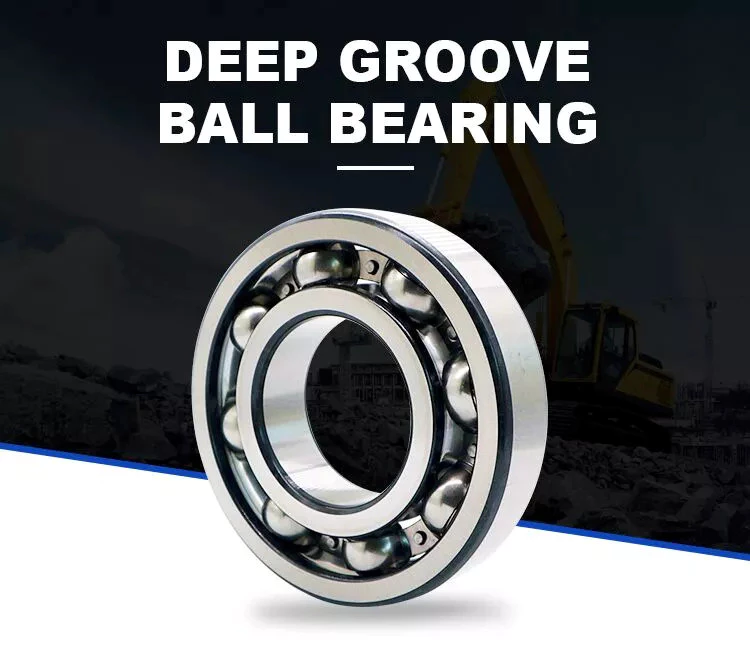
Self-aligning
The self-aligning ball bearing was invented by Sven Wingquist, a plant engineer for a textile company in Sweden. While he was responsible for making production as efficient as possible, he soon realized that the machinery he had in place wasn't working as efficiently as it could. Although ball bearings are great for reducing friction, they were not flexible enough to compensate for misalignments in the machine.
Self-aligning ball bearings have 2 rows of balls and a common sphered raceway. The inner ring is curved and combines the 2 rows of balls into 1 cage. These bearings can tolerate shaft misalignment and compensate for static angular defects. They can be used in simple woodworking machinery, ventilators, and conveying equipment. They are often the preferred choice for applications where shaft alignment is an issue.
Ceramic
A Ceramic ball bearing is a type of high-performance bearing that is available in both full-ceramic and hybrid forms. The main differences between ceramic and steel ball bearings are their construction, lubrication, and mobility. High-quality ceramic ball bearings are durable, and they are ideal for corrosive and high-temperature applications. The material used to create these bearings helps prevent electrolytic corrosion. They are also ideal for reducing the friction and lubrication requirements.
Ceramic balls are harder and less brittle than steel balls, which gives them a higher degree of rigidity. Ceramics also have a higher hardness, with a hardness of Rc75-80 compared to Rc58-64 for steel balls. Their high compressive strength is approximately 5 to 7 times greater than steel. In addition, they have a very low coefficient of friction, which allows them to spin at higher speeds and with less friction. This increases their lifespan and durability, and decreases the energy needed to turn cranks.
Steel
Unlike traditional bearings, steel balls have a relatively uniform hardness. Carbon steel, for instance, is 2.1% carbon by weight. According to the American Iron and Steel Institute, copper content must be no more than 0.40% and manganese content should not be more than 1.65 g/cm3. After carbonizing, steel balls undergo a process called sizing, which improves their roundness geometry and hardness.
The main differences between steel ball bearings and ceramic ball bearings can be traced to their different materials. Ceramic balls are made from zirconium dioxide or silicon nitride. Silicon nitride is harder than steel and resists shocks. The result is increased speed and longer service life. Polyoxymethylene acetal (PMMA) bearing balls are known for their stiffness, strength, and tolerance, but are not as common as steel ball bearings.
Plastic
The most popular types of plastic ball bearings are made of polypropylene or PTFE. These bearings are used in applications requiring higher chemical resistance. Polypropylene is a structural polymer that offers excellent physical and chemical properties, including excellent resistance to organic solvents and degreasing agents. Its lightweight, low moisture absorption rate, and good heat resistance make it an excellent choice for high-temperature applications. However, plastic bearings are not without their drawbacks, especially when operating at very high temperatures or under heavy loads.
Compared to metal bearings, plastic ball-bearings do not require lubrication. They also are highly corrosion-resistant, making them an excellent choice for wash-down applications. They are also post-, autoclave-, and gamma sterilizable. Many conventional steel ball-bearings cannot handle the high temperatures of food processing or swimming pools. In addition to high temperature applications, plastic ball bearings are resistant to chemicals, including chlorine.
Glass
Plastic sliding bearings are molded bearings made of engineering plastic. With self-lubricating modification technology, these bearings can be produced by injection molding of plastic beads. They are widely used in various industries such as office equipment, fitness and automotive equipment. In addition to plastic bearings, glass balls are used in a variety of other applications, including medical equipment. Glass ball bearings have excellent corrosion resistance, excellent mechanical properties, and are electrically insulators.
Plastic ball bearings are made of all-plastic races and cages. These bearings are suitable for applications that are exposed to acids and alkalis. Because they are cheaper than glass balls, plastic ball bearings are popular in chemical-exposed environments. Stainless steel balls are also resistant to heat and corrosion. But the main disadvantage of plastic ball bearings is that they are not as strong as glass balls. So, if weight and noise is your main concern, consider using plastic balls instead.
Miniature
The global miniature ball bearing market is expected to reach US$ 2.39 Billion by 2027, at a CAGR of 7.2%. Growth in the region is attributed to technological advancement and government initiatives. Countries such as India and China are attracting FDIs and emphasizing the establishment of a global manufacturing hub. This is boosting the market for miniature ball bearings. The miniscule ball bearings are manufactured in small quantities and are very small.
Some manufacturers produce miniature ball bearings in different materials and designs. Chrome steel is the most popular material for miniature ball bearings because of its high load capacity, low noise properties, and lower cost. But the cost of stainless steel miniature bearings is low, since the amount of steel used is minimal. Stainless steel miniature bearings are the smallest in size. Therefore, you can choose stainless steel mini ball bearings for high-speed applications.
Angular-contact
Angular-contact ball bearings have 3 components: a cage, inner ring, and balls. Angular-contact ball bearings can support high axial and radial loads. Various design and manufacturing attributes make angular-contact ball bearings suitable for a variety of applications. Some features of this bearing type include a special lubricant, different cage materials, and different coatings.
The size of an angular-contact ball bearing is determined by the design units: outer ring width, axial load, and radial load. Depending on the type of application, an angular-contact ball bearing may be manufactured in double-row, triple-row, or quadruple-row configurations. Angular contact ball bearings can be classified according to their design units, which range from metric to imperial. A higher ABEC number means tighter tolerances. To determine the tolerance equivalent of a particular bearing, consult a standard Angular-contact ball bearing table.
Angular-contact ball bearings feature high and low-shoulder configurations. They have two-dimensional races that accommodate axial and radial loads. They are available in self-retaining units with solid inner and outer rings, and ball and cage assemblies. Cages made of cast and wrought brass are the most popular, but lightweight phenolic cages are also available. The latter is a better choice because it doesn't absorb oil and has lower rolling friction.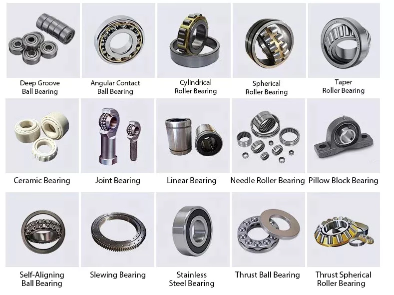
Materials
When it comes to the construction of a ball bearing, high-quality raw materials are a crucial component. These materials not only affect the overall quality of a ball bearing, but also influence the cost. That's why you should pay close attention to raw material quality. In addition to that, raw materials should be tested several times before the manufacturing process to ensure quality. Read on for some information about the different types of materials used to make ball bearings.
Steel is the most common material for ball bearings. Most ball bearings contain stainless steel balls, which are remarkably corrosion-resistant. They are also resistant to saltwater and alkalis. However, stainless steel balls are heavier than plastic ones, and they are also magnetic, which may be a drawback in some applications. If you're looking for a metal-free option, glass balls are the way to go. They're sturdy, lightweight, and resistant to a wide range of chemicals.
China best Low Price High Quality Excavator Ex120-5/-6 Ex110 Arm Boom Bucket Hydraulic Cylinder with high quality
Product Description
low price high quality excavator EX120-5/-6 EX110 arm boom bucket hydraulic cylinder
Bucket cylinder
Boom Cylinder
Arm Cylinder
Hydraulic Cllinder
Product Details
| Specifications of Excavator Arm Cylinder |
| 1.Supply to USA,Europe,and Australia, Russia. |
| 2.Material:Stainless Steel |
| 3.Professional performance excavator parts supplier |
| 4. High quality and low price |
Product Features
1. Seals kit: Superior quality named-brand seals, durable and hard-wearing with long service life.
2. Heat treatment: Quenching&Tempering which makes the piston rod super high hardness.
3. Cleaning: Ultrasonic cleaning.
4.Rod:Induction hardened prior to chrome plating enhances the surface hardness, improve corrosion resistance and anti-scratch performance.
5.Bushing: Hardened steel bushing or copper bushing.
6.Cap: all caps are made of forged high strength steel.
7.Piston: High pressure piston sealing material. Teflon or nylon seals, High precision machining maximize the consistency of parts
8. Testing: Ultrasonic detector, spectrograph, CMM, metallography, chrome thickness tester.
9. Advantage: Simple structure & reliable work, easy maintenance & diverse connecting ways.
Product Application
Hydraulic Cylinder Product Application:
Applications in a wide variety of worldwide industries, including manufacturing engineering machinery, construction, forestry, waste management, mining, material handling, industrial applications, agriculture, manufacturing, transportation, marine applications and oil field equipment.
Packing&Delivery
Packing detals:Standard export fumigated wooden pallet
Nearest Port:HangZhou, HangZhou, HangZhou
Advantage
1) high quality material
2) high performance&durable quality
3) passed ISO9001, national standard
4) cooperate with TAKEUCHI, BAUER, SHXIHU (WEST LAKE) DIS.I,
ASTEC,ITOCHU for many years
5) direct factory price
6) 10 years' of manufacturing experience
7) owns entire production process and strict QCS
Our Related Products
About us
Founded in 2008, HangZhou CZPT Engineering Machinery Co., Ltd. is located in HangZhou city, ZheJiang province, near to HangZhou port with convenient transportation. Our company is a professional manufacturer and exporter of undercarriage parts for excavators and bulldozers in China.
Our main products include track roller, top roller, idler, sprocket, track shoe, track links, track group, track bolt with nut, bucket, bucket link, teeth, and cylinder ect. These parts are applied for Caterpillar, Komatsu, Hitachi, Kato, Daewoo, Hyundai, Sumitomo, Samsung, Kobelco, and Mitsubishi. With more than 12 years' development, our company have all kinds of production lines, professional technicians and skillful workers, making sure our products with high quality and competitive price. We passed the certification of ISO9001-2000, quality management procedures are conducted in accordance with international standards.
Now all our products are exported to Southeast Asia, the Middle East, Europe, North and South America, Australia, and Africa and so on. We are enhancing the market share. "Mutual benefit" is our promise and value. We'd like to supply you with high quality products and professional after-sales service. We sincerely welcome you to join us for mutual development and a prosperous future!
FAQ
Q: Are you trading company or manufacturer ?
A: We are manufacturer ,our factory located in HangZhou.We will 100% factory price to you.
Q: How long is your delivery time?
A: Generally it is 7 days if the goods are in stock. or it is 20-30 days if not in stock. If it is customized,it will be confirmed according to order.
Q: What about Quality Control?
A:We have excellent tester, check every piece to ensure the quality is good, and check the quantity is correct before the shipment.
Q: How to order ?
A:Tell us the machine model,part name, part number, quanitty for each item, and then we can send a professional quotation sheet.
Benefits and Uses of Miter Gears
If you've ever looked into the differences between miter gears, you're probably wondering how to choose between a Straight toothed and Hypoid one. Before you decide, however, make sure you know about backlash and what it means. Backlash is the difference between the addendum and dedendum, and it prevents jamming of the gears, protects the mating gear surfaces, and allows for thermal expansion during operation.
Spiral bevel gears
Spiral bevel gears are designed to increase efficiency and reduce cost. The spiral shape creates a profile in which the teeth are cut with a slight curve along their length, making them an excellent choice for heavy-duty applications. Spiral bevel gears are also hypoid gears, with no offsets. Their smaller size means that they are more compact than other types of right-angle gears, and they are much quieter than other types of gear.
Spiral bevel gears feature helical teeth arranged in a 90-degree angle. The design features a slight curve to the teeth, which reduces backlash while increasing flexibility. Because they have no offsets, they won't slip during operation. Spiral bevel gears also have less backlash, making them an excellent choice for high-speed applications. They are also carefully spaced to distribute lubricant over a larger area. They are also very accurate and have a locknut design that prevents them from moving out of alignment.
In addition to the geometric design of bevel gears, CZPT can produce 3D models of spiral bevel gears. This software has gained widespread attention from many companies around the world. In fact, CZPT, a major manufacturer of 5-axis milling machines, recently machined a prototype using a spiral bevel gear model. These results prove that spiral bevel gears can be used in a variety of applications, ranging from precision machining to industrial automation.
Spiral bevel gears are also commonly known as hypoid gears. Hypoid gears differ from spiral bevel gears in that their pitch surface is not at the center of the meshing gear. The benefit of this gear design is that it can handle large loads while maintaining its unique features. They also produce less heat than their bevel counterparts, which can affect the efficiency of nearby components.
Straight toothed miter gears
Miter gears are bevel gears that have a pitch angle of 90 degrees. Their gear ratio is 1:1. Miter gears come in straight and spiral tooth varieties and are available in both commercial and high precision grades. They are a versatile tool for any mechanical application. Below are some benefits and uses of miter gears. A simple explanation of the basic principle of this gear type is given. Read on for more details.
When selecting a miter gear, it is important to choose the right material. Hard faced, high carbon steel is appropriate for applications requiring high load, while nylon and injection molding resins are suitable for lower loads. If a particular gear becomes damaged, it's advisable to replace the entire set, as they are closely linked in shape. The same goes for spiral-cut miter gears. These geared products should be replaced together for proper operation.
Straight bevel gears are the easiest to manufacture. The earliest method was using an indexing head on a planer. Modern manufacturing methods, such as the Revacycle and Coniflex systems, made the process more efficient. CZPT utilizes these newer manufacturing methods and patented them. However, the traditional straight bevel is still the most common and widely used type. It is the simplest to manufacture and is the cheapest type.
SDP/Si is a popular supplier of high-precision gears. The company produces custom miter gears, as well as standard bevel gears. They also offer black oxide and ground bore and tooth surfaces. These gears can be used for many industrial and mechanical applications. They are available in moderate quantities from stock and in partial sizes upon request. There are also different sizes available for specialized applications.
Hypoid bevel gears
The advantages of using Hypoid bevel and helical gears are obvious. Their high speed, low noise, and long life make them ideal for use in motor vehicles. This type of gear is also becoming increasingly popular in the power transmission and motion control industries. Compared to standard bevel and helical gears, they have a higher capacity for torque and can handle high loads with less noise.
Geometrical dimensioning of bevel/hypoid bevel gears is essential to meet ANSI/AGMA/ISO standards. This article examines a few ways to dimension hypoid bevel and helical gears. First, it discusses the limitations of the common datum surface when dimensioning bevel/helical gear pairs. A straight line can't be parallel to the flanks of both the gear and the pinion, which is necessary to determine "normal backlash."
Second, hypoid and helical gears have the same angular pitch, which makes the manufacturing process easier. Hypoid bevel gears are usually made of 2 gears with equal angular pitches. Then, they are assembled to match 1 another. This reduces noise and vibration, and increases power density. It is recommended to follow the standard and avoid using gears that have mismatched angular pitches.
Third, hypoid and helical gears differ in the shape of the teeth. They are different from standard gears because the teeth are more elongated. They are similar in appearance to spiral bevel gears and worm gears, but differ in geometry. While helical gears are symmetrical, hypoid bevel gears are non-conical. As a result, they can produce higher gear ratios and torque.
Crown bevel gears
The geometrical design of bevel gears is extremely complex. The relative contact position and flank form deviations affect both the paired gear geometry and the tooth bearing. In addition, paired gears are also subject to process-linked deviations that affect the tooth bearing and backlash. These characteristics require the use of narrow tolerance fields to avoid quality issues and production costs. The relative position of a miter gear depends on the operating parameters, such as the load and speed.
When selecting a crown bevel gear for a miter-gear system, it is important to choose 1 with the right tooth shape. The teeth of a crown-bevel gear can differ greatly in shape. The radial pitch and diametral pitch cone angles are the most common. The tooth cone angle, or "zerol" angle, is the other important parameter. Crown bevel gears have a wide range of tooth pitches, from flat to spiral.
Crown bevel gears for miter gear are made of high-quality materials. In addition to metal, they can be made of plastic or pre-hardened alloys. The latter are preferred as the material is less expensive and more flexible than steel. Furthermore, crown bevel gears for miter gears are extremely durable, and can withstand extreme conditions. They are often used to replace existing gears that are damaged or worn.
When selecting a crown bevel gear for a miter gear, it is important to know how they relate to each other. This is because the crown bevel gears have a 1:1 speed ratio with a pinion. The same is true for miter gears. When comparing crown bevel gears for miter gears, be sure to understand the radii of the pinion and the ring on the pinion.
Shaft angle requirements for miter gears
Miter gears are used to transmit motion between intersecting shafts at a right angle. Their tooth profile is shaped like the mitre hat worn by a Catholic bishop. Their pitch and number of teeth are also identical. Shaft angle requirements vary depending on the type of application. If the application is for power transmission, miter gears are often used in a differential arrangement. If you're installing miter gears for power transmission, you should know the mounting angle requirements.
Shaft angle requirements for miter gears vary by design. The most common arrangement is perpendicular, but the axes can be angled to almost any angle. Miter gears are also known for their high precision and high strength. Their helix angles are less than 10 degrees. Because the shaft angle requirements for miter gears vary, you should know which type of shaft angle you require before ordering.
To determine the right pitch cone angle, first determine the shaft of the gear you're designing. This angle is called the pitch cone angle. The angle should be at least 90 degrees for the gear and the pinion. The shaft bearings must also be capable of bearing significant forces. Miter gears must be supported by bearings that can withstand significant forces. Shaft angle requirements for miter gears vary from application to application.
For industrial use, miter gears are usually made of plain carbon steel or alloy steel. Some materials are more durable than others and can withstand higher speeds. For commercial use, noise limitations may be important. The gears may be exposed to harsh environments or heavy machine loads. Some types of gears function with teeth missing. But be sure to know the shaft angle requirements for miter gears before you order one.
China high quality Cat Excavator Boom Cylinder E200b E320b E320d E325 E330 Arm Bucket Hydraulic Oil Cylinder near me manufacturer
Product Description
CAT Excavator Boom Cylinder E200B E320B E320D E325 E330 Arm Bucket Hydraulic Oil Cylinder
Brand catalog:
Excavator
Komatsu: PC30, PC40, PC45, PC60, PC75, PC100, PC120, PC150, PC200, PC220, PC300, PC350, and PC400
Caterpillar: E70B, E110, E120B, E215, E235, E307, E311, E312, E322, E180, E240, E200B, E320, E300, E300B, E330, and E325
Daewoo: DH55, DH200, DH220, and DH280
Hitachi: EX30, EX40, EX60, EX100, EX120, EX200, EX220, EX270, EX300, EX400, EX600, UH043, UH052, UH053, UH07, UH081, UH082, CZPT UH083
Hitachi: FH120, FH130, FH150, FH200, FH220, FH270, and FH300
Hyundai: R55, R60, R70, R80, R110, R130, R150, and R200
KATO: HD140, HD250, HD400, HD450, HD550, HD700, HD820, HD850, HD880, HD900, HD1220, and HD1250
KOBELCO: SK40, SK60, SK100, SK120, SK200, SK220, SK04-2, SK07, SK07N2, SK09, SK12, SK14, SK300, SK310, and SK400
Mitsubishi: MS110, MS120, MS180, MS230, and MS280
Samsung H.I.: MX8, SE200, SE210, SE280, and MX292
SUMITOMO: SH70, SH100, SH120, SH160, SH200, SH260, SH265, SH280, SH300, SH340, LS2650, LS2800, LS3400, and LS4300
Bulldozer:
Caterpillar Bulldozer: D3, D3C, D3L, D3D, D4, D4C, D4D, D4H, D5, D6, D6C, D6D, D6H, D7, D7G, D8K, and D8N
Komatsu Bulldozer: D20, D30, D31, D37, D40, D41, D45, D50, D53, D57, D58, D60, D63, D65, D68, D75, D80, D85, D95, D135, D150, and D155
CAT Excavator Boom Cylinder E200B E320B E320D E325 E330 Arm Bucket Hydraulic Oil Cylinder
Product Name:Hydraulic Cylinder
Application:Excavator Attachment
Color:Customer Required
MOQ:1 Piece
Material:Q345B
Package:Standard Export Packaging
Model:Standard
Quality:High-Quality
Type:Fittings
Characteristics:Strong
About us
We are ZheJiang CZPT Imp & Exp Co., Ltd, specialize in providing EXCAVATOR BUCKET and UNDERCARRIAGE PARTS for Excavator and Bulldozer, the brand include CAT, Komatsu, Volvo, Shantui, Hitachi, Kobelco, Hyundai, Doosan, Sumitomo, CZPT and other well-known brands.
VOCHAINS wide range of Undercarriage Parts & Components including:
- Track Chains (Standard, Heavy Duty & "PPR" Series)
- Forged and Cast Drive Segments
- Drive Sprockets
- Idlers
- Lower Rollers
- Carrier Rollers
- Track Tensioning Assemblies and Components
- Heavy Duty Forestry Roller and Idlers
Contact us
| Nancy --------------------- Sale Manager ZheJiang CZPT Imp & Exp Co. Ltd. Add: HangZhou City, ZheJiang Provice, China Mobile: |
Types of Bevel Gears
Bevel Gears are used in a number of industries. They are used in wheeled excavators, dredges, conveyor belts, mill actuators, and rail transmissions. A bevel gear's spiral or angled bevel can make it suitable for confined spaces. It is also used in robotics and vertical supports of rolling mills. You can use bevel gears in food processing processes. For more information on bevel gears, read on.
Spiral bevel gear
Spiral bevel gears are used to transmit power between 2 shafts in a 90-degree orientation. They have curved or oblique teeth and can be fabricated from various metals. Bestagear is 1 manufacturer specializing in medium to large spiral bevel gears. They are used in the mining, metallurgical, marine, and oil fields. Spiral bevel gears are usually made from steel, aluminum, or phenolic materials.
Spiral bevel gears have many advantages. Their mesh teeth create a less abrupt force transfer. They are incredibly durable and are designed to last a long time. They are also less expensive than other right-angle gears. They also tend to last longer, because they are manufactured in pairs. The spiral bevel gear also reduces noise and vibration from its counterparts. Therefore, if you are in need of a new gear set, spiral bevel gears are the right choice.
The contact between spiral bevel gear teeth occurs along the surface of the gear tooth. The contact follows the Hertz theory of elastic contact. This principle holds for small significant dimensions of the contact area and small relative radii of curvature of the surfaces. In this case, strains and friction are negligible. A spiral bevel gear is a common example of an inverted helical gear. This gear is commonly used in mining equipment.
Spiral bevel gears also have a backlash-absorbing feature. This feature helps secure the thickness of the oil film on the gear surface. The shaft axis, mounting distance, and angle errors all affect the tooth contact on a spiral bevel gear. Adjusting backlash helps to correct these problems. The tolerances shown above are common for bevel gears. In some cases, manufacturers make slight design changes late in the production process, which minimizes the risk to OEMs.
Straight bevel gear
Straight bevel gears are among the easiest types of gears to manufacture. The earliest method used to manufacture straight bevel gears was to use a planer equipped with an indexing head. However, improvements have been made in manufacturing methods after the introduction of the Revacycle system and the Coniflex. The latest technology allows for even more precise manufacturing. Both of these manufacturing methods are used by CZPT. Here are some examples of straight bevel gear manufacturing.
A straight bevel gear is manufactured using 2 kinds of bevel surfaces, namely, the Gleason method and the Klingelnberg method. Among the two, the Gleason method is the most common. Unlike other types of gear, the CZPT method is not a universal standard. The Gleason system has higher quality gears, since its adoption of tooth crowning is the most effective way to make gears that tolerate even small assembly errors. It also eliminates the stress concentration in the bevelled edges of the teeth.
The gear's composition depends on the application. When durability is required, a gear is made of cast iron. The pinion is usually 3 times harder than the gear, which helps balance wear. Other materials, such as carbon steel, are cheaper, but are less resistant to corrosion. Inertia is another critical factor to consider, since heavier gears are more difficult to reverse and stop. Precision requirements may include the gear pitch and diameter, as well as the pressure angle.
Involute geometry of a straight bevel gear is often computed by varying the surface's normal to the surface. Involute geometry is computed by incorporating the surface coordinates and the theoretical tooth thickness. Using the CMM, the spherical involute surface can be used to determine tooth contact patterns. This method is useful when a roll tester tooling is unavailable, because it can predict the teeth' contact pattern.
Hypoid bevel gear
Hypoid bevel gears are an efficient and versatile speed reduction solution. Their compact size, high efficiency, low noise and heat generation, and long life make them a popular choice in the power transmission and motion control industries. The following are some of the benefits of hypoid gearing and why you should use it. Listed below are some of the key misperceptions and false assumptions of this gear type. These assumptions may seem counterintuitive at first, but will help you understand what this gear is all about.
The basic concept of hypoid gears is that they use 2 non-intersecting shafts. The smaller gear shaft is offset from the larger gear shaft, allowing them to mesh without interference and support each other securely. The resulting torque transfer is improved when compared to conventional gear sets. A hypoid bevel gear is used to drive the rear axle of an automobile. It increases the flexibility of machine design and allows the axes to be freely adjusted.
In the first case, the mesh of the 2 bodies is obtained by fitting the hyperboloidal cutter to the desired gear. Its geometric properties, orientation, and position determine the desired gear. The latter is used if the desired gear is noise-free or is required to reduce vibrations. A hyperboloidal cutter, on the other hand, meshes with 2 toothed bodies. It is the most efficient option for modeling hypoid gears with noise concerns.
The main difference between hypoid and spiral bevel gears is that the hypoid bevel gear has a larger diameter than its counterparts. They are usually found in 1:1 and 2:1 applications, but some manufacturers also provide higher ratios. A hypoid gearbox can achieve speeds of 3 thousand rpm. This makes it the preferred choice in a variety of applications. So, if you're looking for a gearbox with a high efficiency, this is the gear for you.
Addendum and dedendum angles
The addendum and dedendum angles of a bevel gear are used to describe the shape and depth of the teeth of the gear. Each tooth of the gear has a slightly tapered surface that changes in depth. These angles are defined by their addendum and dedendum distances. Addendum angle is the distance between the top land and the bottom surface of the teeth, while dedendum angle is the distance between the pitch surface and the bottom surface of the teeth.
The pitch angle is the angle formed by the apex point of the gear's pitch cone with the pitch line of the gear shaft. The dedendum angle, on the other hand, is the depth of the tooth space below the pitch line. Both angles are used to measure the shape of a bevel gear. The addendum and dedendum angles are important for gear design.
The dedendum and addendum angles of a bevel gear are determined by the base contact ratio (Mc) of the 2 gears. The involute curve is not allowed to extend within the base diameter of the bevel gear. The base diameter is also a critical measurement for the design of a gear. It is possible to reduce the involute curve to match the involute curve, but it must be tangential to the involute curve.
The most common application of a bevel gear is the automotive differential. They are used in many types of vehicles, including cars, trucks, and even construction equipment. They are also used in the marine industry and aviation. Aside from these 2 common uses, there are many other uses for bevel gears. And they are still growing in popularity. But they're a valuable part of automotive and industrial gearing systems.
Applications of bevel gears
Bevel gears are used in a variety of applications. They are made of various materials depending on their weight, load, and application. For high-load applications, ferrous metals such as grey cast iron are used. These materials have excellent wear resistance and are inexpensive. For lower-weight applications, steel or non-metals such as plastics are used. Some bevel gear materials are considered noiseless. Here are some of their most common uses.
Straight bevel gears are the easiest to manufacture. The earliest method of manufacturing them was with a planer with an indexing head. Modern manufacturing methods introduced the Revacycle and Coniflex systems. For industrial gear manufacturing, the CZPT uses the Revacycle system. However, there are many types of bevel gears. This guide will help you choose the right material for your next project. These materials can withstand high rotational speeds and are very strong.
Bevel gears are most common in automotive and industrial machinery. They connect the driveshaft to the wheels. Some even have a 45-degree bevel. These gears can be placed on a bevel surface and be tested for their transmission capabilities. They are also used in testing applications to ensure proper motion transmission. They can reduce the speed of straight shafts. Bevel gears can be used in many industries, from marine to aviation.
The simplest type of bevel gear is the miter gear, which has a 1:1 ratio. It is used to change the axis of rotation. The shafts of angular miter bevel gears can intersect at any angle, from 45 degrees to 120 degrees. The teeth on the bevel gear can be straight, spiral, or Zerol. And as with the rack and pinion gears, there are different types of bevel gears.