Product Description
Factory Supply Construction Machinery Excavator Spare Parts Hydraulic Cylinder Made in China
Product Specifications :
| Item | Specifications |
| Bore diameter | 60mm-250mm,customizable |
| Bod diameter | 40mm-230mm,customizable |
| Stroke | 100mm-400mm,customizable |
| Working Pressure | 7-40Mpa,customizable |
| Surface treatment of piston rod | HaHard Chrome Plating,Electroplated Milky White Chromium+Hard Chromium,Nickel Plating+Hard Chromium Plating,High-Velocity Oxygen-Fuel CrC NiC,Ceramic Coating,Nitriding,Laser Cladding |
| Work Pressure | Maximum 38MPa,Customizable |
| Material | High tensile cold drawn tube, precision honed for extended seal life |
| Mounting | Earring,Flange,Clevis.Foot,Trunnion,Customizable |
| Seal Type | Parker,NOK, Hallite or as customer's requirement |
| Warrenty | 18 months |
| MOQ | 1 pcs |
| Production Time | Based on order quantity.normally 30-40 days. |
| Certification | ISO9001,CE, SGS |
| Packaging | metal case,plywood case,carton or as requirement |
| Service | OEM & ODM |
| Warranty arranwarranty ty | 18 months,customizable |
| Color | customizable |
| Price Advantage | Competitive factory price with guaranteed quality |
| Business Type | Manufacturer |
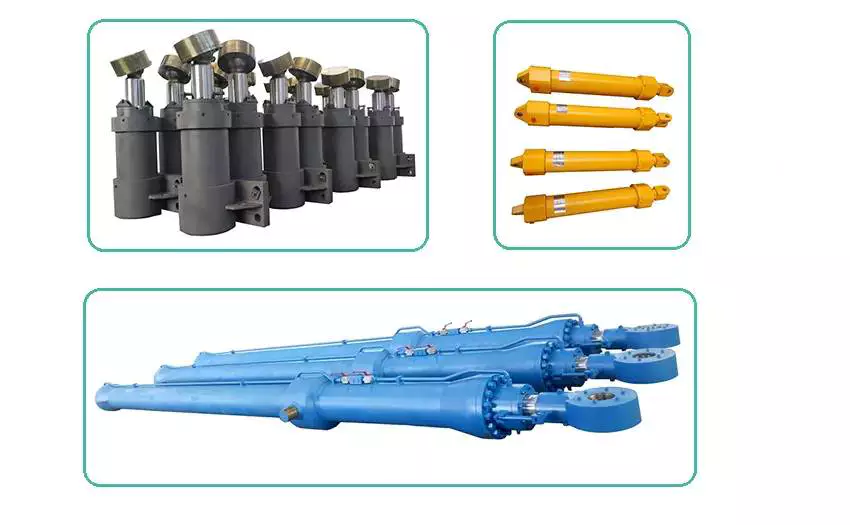
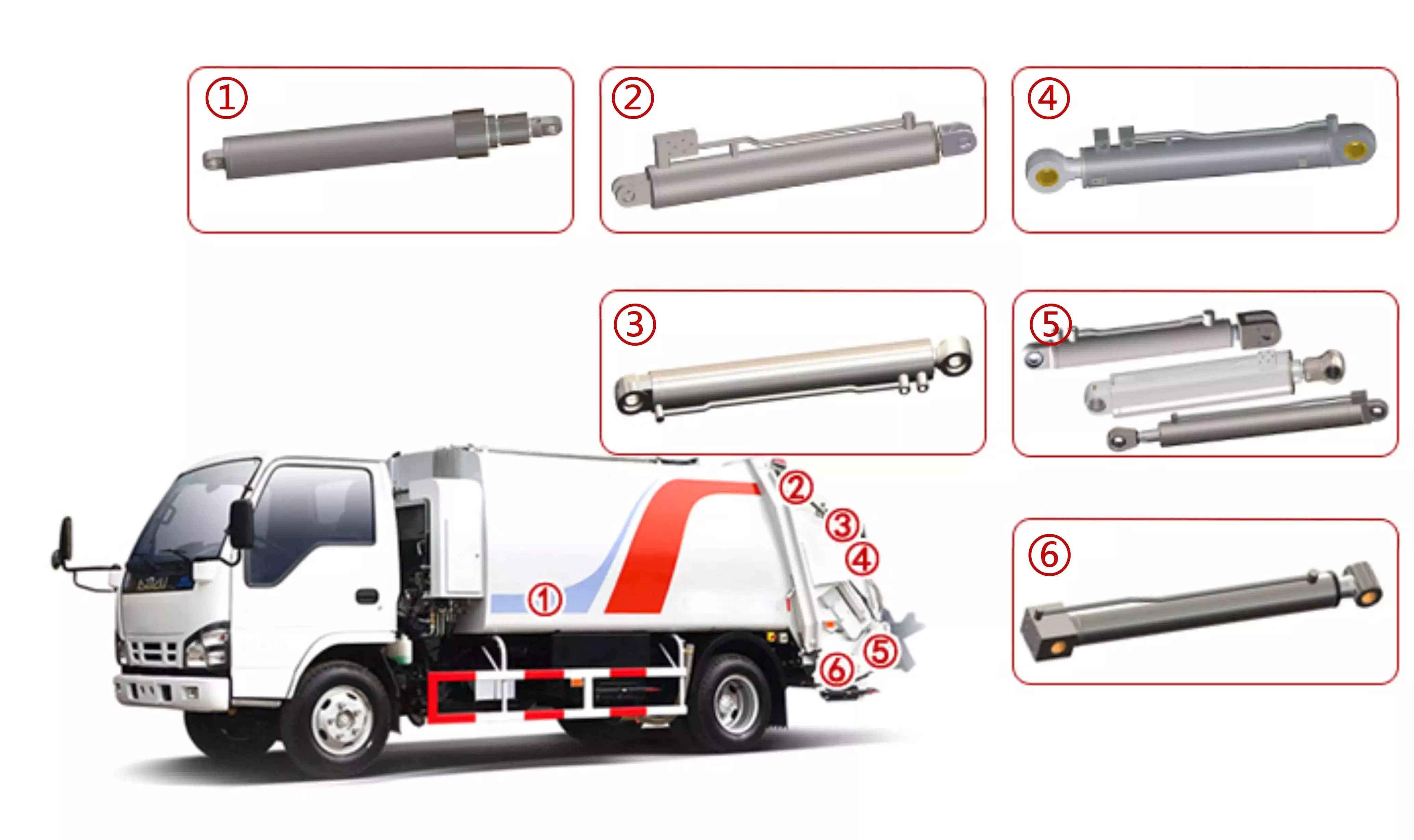
Product Display:
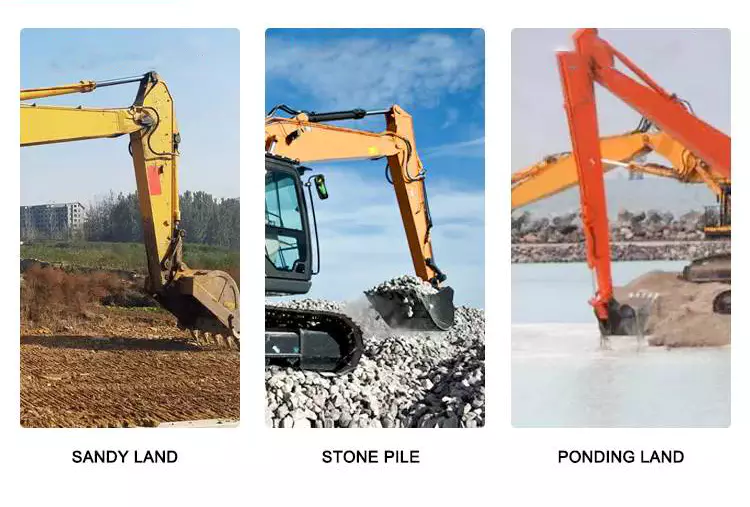
Appliactions:Walking machinery,excavator.
Mounting Method:
Other Products:
Our Factory:
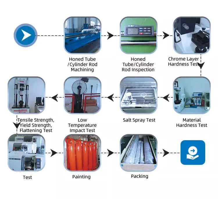
Inspection Process:
| Inspection Type | Inspection Standard |
| Raw Material Inspection | Before storage, QC takes the measurement of the raw materials. |
| Process Material Inspection | During the production, QCs conduct a random inspection. Before the hydraulic cylinder parts transferred to the next process, QCs takes inspection. |
| Final Function Testing | All the hydraulic cylinders take hydraulic function test |
Inspection of Mechanical Properties of Raw Materials
Process Inspection
Final Testing
Packing & Delivery:
About US:
Our Certificate
Our Main Customers
ZheJiang Tianjian Hydraulic Technology Co.,Ltd is specializing in the production of various types of hydraulic cylinders as well as cylinder barrel, piston cylinder and other cylinder accessories.
As a highly specialized manufacturer of hydraulic cylinders, tianjian provides design optimization solutions and reliable products to many customers at home and abroad. No matter in construction machinery, railway bridge machinery, port ship machinery, metallurgy and mining machinery, oil and light industry machinery, special vehicles and other industries, tianjian can provide various standard and non-standard hydraulic cylinder design optimization schemes and products according to users' requirements, and provide integrated services for perfection and quality.
If possible, when contact with us, please apply information as below
|
Bore |
Rod |
Stroke |
Work Pressure |
Mounting |
Work environment |
|
|
|
|
|
|
|
Or you can offer us your sketch diagram or photos so that we could understand you exactly meaning, help us avoid mistakes.
And if you have samples, we can manufacture according to your samples after sending to us.
Welcome to our factory if you have any time.
Your satisfaction is our biggest motivation.
Now, you can contact with us for any question or inquiry.
FAQ:
1, What does your company do?
A: we are a supplier of high quality hydraulic products including Hydraulic Cylinder, Hydraulic Motor, Hydraulic Power Pack, Hydraulic station and other Hydraulic components.
2, Are you a manufacture or a trading company?
A: We are a manufacturer.
3, What certificate do you have?
A: All our factories are ISO certificated. And our main suppliers of materials and parts are with CE, RoHS, CSA and UL certificates.
4, How long is your delivery time?
A: The delivery time depends on different products and quantity. The cylinder usually need about 45-60 days and the Motor need about 30-50 days.
5, Can you make parts as customer's requirement or drawing?
A: Yes, we can OEM for you as your drawings. Our engineer also can give you professional support for technical suggestions.
6, What kind of payment terms do you accept?
A: We prefer T/T through bank. 30% when order is confirmed and 70% before shipment. L/C is also acceptable for amount over 20,000USD.
7, What is your warranty policy?
A: All our products are warranted for 1 full year from date of delivery against defects in materials and workmanship. This warranty does not cover parts that are worn out through the course of normal operation or are damaged through negligence. We serious remind that unclean hydraulic oil will definitely cause damage to your Hydraulic components. And this damage is not included in the warranty range. So we strongly suggest you to use new clean oil or make sure the system oil are clean when using our parts
/* March 10, 2571 17:59:20 */!function(){function s(e,r){var a,o={};try{e&&e.split(",").forEach(function(e,t){e&&(a=e.match(/(.*?):(.*)$/))&&1
| Certification: | GS, RoHS, CE, ISO9001 |
|---|---|
| Pressure: | Medium Pressure |
| Work Temperature: | High Temperature |
| Acting Way: | Double Acting |
| Working Method: | Straight Trip |
| Adjusted Form: | Regulated Type |
| Samples: |
US$ 300/Set
1 Set(Min.Order) | |
|---|
| Customization: |
Available
|
|
|---|
How do hydraulic cylinders compare to other methods of force generation like electric motors?
Hydraulic cylinders and electric motors are two different methods of force generation with distinct characteristics and applications. While both hydraulic cylinders and electric motors can generate force, they differ in terms of their working principles, performance attributes, and suitability for specific applications. Here's a detailed comparison of hydraulic cylinders and electric motors:
1. Working Principle:
- Hydraulic Cylinders: Hydraulic cylinders generate force through the conversion of fluid pressure into linear motion. They consist of a cylinder barrel, piston, piston rod, and hydraulic fluid. When pressurized hydraulic fluid enters the cylinder, it pushes against the piston, causing the piston rod to extend or retract, thereby generating linear force.
- Electric Motors: Electric motors generate force through the conversion of electrical energy into rotational motion. They consist of a stator, rotor, and electromagnetic field. When an electrical current is applied to the motor's windings, it creates a magnetic field that interacts with the rotor, causing it to rotate and generate torque.
2. Force and Power:
- Hydraulic Cylinders: Hydraulic cylinders are known for their high force capabilities. They can generate substantial linear forces, making them suitable for heavy-duty applications that require lifting, pushing, or pulling large loads. Hydraulic systems can provide high force output even at low speeds, allowing for precise control over force application. However, hydraulic systems typically operate at lower speeds compared to electric motors.
- Electric Motors: Electric motors excel in providing high rotational speeds and are commonly used for applications that require rapid motion. While electric motors can generate significant torque, they tend to have lower force output compared to hydraulic cylinders. Electric motors are suitable for applications that involve continuous rotary motion, such as driving conveyor belts, rotating machinery, or powering vehicles.
3. Control and Precision:
- Hydraulic Cylinders: Hydraulic systems offer excellent control over force, speed, and positioning. By regulating the flow of hydraulic fluid, the force and speed of hydraulic cylinders can be precisely controlled. Hydraulic systems can provide gradual acceleration and deceleration, allowing for smooth and precise movements. This level of control makes hydraulic cylinders well-suited for applications that require precise positioning, such as in industrial automation or construction equipment.
- Electric Motors: Electric motors also offer precise control over speed and positioning. Through motor control techniques such as varying voltage, frequency, or pulse width modulation (PWM), the rotational speed and position of electric motors can be accurately controlled. Electric motors are commonly used in applications that require precise speed control, such as robotics, CNC machines, or servo systems.
4. Efficiency and Energy Consumption:
- Hydraulic Cylinders: Hydraulic systems can be highly efficient, especially when properly sized and designed. However, hydraulic systems typically have higher energy losses due to factors such as fluid leakage, friction, and heat generation. The overall efficiency of a hydraulic system depends on the design, component selection, and maintenance practices. Hydraulic systems require a hydraulic power unit to pressurize the hydraulic fluid, which consumes additional energy.
- Electric Motors: Electric motors can have high efficiency, especially when operated at their optimal operating conditions. Electric motors have lower energy losses compared to hydraulic systems, primarily due to the absence of fluid leakage and lower friction losses. The overall efficiency of an electric motor depends on factors such as motor design, load conditions, and control techniques. Electric motors require an electrical power source, and their energy consumption depends on the motor's power rating and the duration of operation.
5. Environmental Considerations:
- Hydraulic Cylinders: Hydraulic systems typically use hydraulic fluids that can pose environmental concerns if they leak or are not properly disposed of. The choice of hydraulic fluid can impact factors such as biodegradability, toxicity, and potential environmental hazards. Proper maintenance and leak prevention practices are essential to minimize the environmental impact of hydraulic systems.
- Electric Motors: Electric motors are generally considered more environmentally friendly since they do not require hydraulic fluids. However, the environmental impact of electric motors depends on the source of electricity used to power them. When powered by renewable energy sources, such as solar or wind, electric motors can offer a greener solution compared to hydraulic systems.
6. Application Suitability:
- Hydraulic Cylinders: Hydraulic cylinders are commonly used in applications that require high force output, precise control, and durability. They are widely employed in industries such as construction, manufacturing, mining, and aerospace. Hydraulic systems are well-suited for heavy-duty applications, such as lifting heavy objects, operating heavy machinery, or controlling large-scale movements.
- Electric Motors: Electric motors are widely used in various industries and applications that require rotational motion, speed control, and precise positioning. They are commonly found in appliances, transportation, robotics, HVAC systems, and automation. Electric motorsare suitable for applications that involve continuous rotary motion, such as driving conveyor belts, rotating machinery, or powering vehicles.In summary, hydraulic cylinders and electric motors have different working principles, force capabilities, control characteristics, efficiency levels, and application suitability. Hydraulic cylinders excel in providing high force output, precise control, and durability, making them ideal for heavy-duty applications. Electric motors, on the other hand, offer high rotational speeds, precise speed control, and are commonly used for applications that involve continuous rotary motion. The choice between hydraulic cylinders and electric motors depends on the specific requirements of the application, including the type of motion, force output, control precision, and environmental considerations.
What considerations are important when selecting hydraulic cylinders for mobile equipment?
To select hydraulic cylinders for mobile equipment, several important considerations need to be taken into account. Here are the key factors to consider:
- Load Capacity: Determine the maximum load or force that the hydraulic cylinder will need to support. This includes both the static load and any dynamic or shock loads that may be encountered during operation.
- Stroke Length: Consider the required stroke length, which is the distance the hydraulic cylinder can extend and retract. Ensure that the stroke length is sufficient for the specific application and range of motion needed.
- Operating Pressure: Determine the maximum operating pressure required for the hydraulic system. This will depend on the load and the specific application. Select a hydraulic cylinder with a pressure rating that exceeds the maximum operating pressure to ensure safety and durability.
- Mounting Style: Consider the available space and the mounting requirements of the mobile equipment. Hydraulic cylinders come in various mounting styles, such as flange, trunnion, clevis, and pivot, among others. Choose a mounting style that is compatible with the equipment and provides the necessary support and stability.
- Size and Weight: Take into account the physical dimensions and weight of the hydraulic cylinder. Ensure that it can fit within the available space and that the equipment can support its weight without compromising performance or safety.
- Speed and Precision: Evaluate the required speed and precision of the hydraulic cylinder's movement. Different cylinder designs and configurations can affect the speed and accuracy of motion. Consider factors such as cylinder bore size, rod diameter, and the presence of cushioning or dampening features.
- Environmental Factors: Assess the operating environment of the mobile equipment. Consider factors such as temperature extremes, exposure to moisture, dust, and chemicals. Select hydraulic cylinders with appropriate seals and coatings that can withstand the environmental conditions and prevent corrosion or damage.
- Reliability and Maintenance: Consider the reliability and maintenance requirements of the hydraulic cylinders. Look for reputable manufacturers that provide high-quality products with a proven track record. Evaluate factors such as expected service life, availability of spare parts, and ease of maintenance.
- Cost: Finally, consider the cost of the hydraulic cylinders, including the initial purchase price, installation costs, and long-term maintenance expenses. While it is essential to find a cost-effective solution, prioritize quality and performance to ensure safe and efficient operation.
What maintenance practices are essential for extending the lifespan of hydraulic cylinders?
Maintaining hydraulic cylinders is crucial for extending their lifespan and ensuring optimal performance. Regular maintenance helps prevent premature wear, damage, and failure, ultimately reducing downtime and saving costs. Here are some essential maintenance practices to consider for extending the lifespan of hydraulic cylinders:
1. Regular Inspections:
- Conduct routine visual inspections of hydraulic cylinders to identify any signs of damage, leaks, or wear. Inspect the cylinder body, piston rod, seals, and mounting points. Look for fluid leaks, rust, dents, or any abnormal wear patterns. Early detection of issues allows for timely repairs or replacements, preventing further damage and extending the lifespan of the cylinder.
2. Cleanliness:
- Maintain a clean environment around hydraulic cylinders to prevent contaminants from entering the system. Dust, dirt, and debris can damage seals and other internal components, leading to accelerated wear and reduced performance. Regularly clean the cylinder and its surroundings to minimize the risk of contamination.
3. Proper Lubrication:
- Adequate lubrication is critical for the smooth operation and longevity of hydraulic cylinders. Follow the manufacturer's recommendations for lubrication intervals and use the appropriate lubricant. Apply lubrication to the cylinder's moving parts, such as the piston rod, to reduce friction and minimize wear.
4. Seal Maintenance:
- Seals play a vital role in preventing hydraulic fluid leaks and maintaining the cylinder's performance. Inspect and replace worn or damaged seals promptly. Ensure that seals are properly installed and lubricated. Regularly clean the seal grooves to remove any debris that could compromise seal effectiveness.
5. Pressure Checks:
- Periodically check the hydraulic system's pressure to ensure it is within the recommended operating range. Excessive pressure can strain the cylinder and its components, leading to premature wear. Monitor pressure levels and make adjustments as necessary to prevent overloading the cylinder.
6. Control Valve Maintenance:
- Maintain and inspect control valves that regulate the flow and direction of hydraulic fluid. Ensure that the valves are functioning correctly and not causing excessive stress or pressure spikes in the cylinder. Clean or replace control valves if they are damaged or malfunctioning.
7. Cylinder Alignment:
- Proper alignment of hydraulic cylinders is essential for their longevity. Misalignment can cause excessive side loads, leading to uneven wear and potential damage. Ensure that the cylinder is correctly aligned with other components and that the mounting points are secure.
8. Preventing Overloading:
- Avoid subjecting hydraulic cylinders to loads exceeding their rated capacity. Overloading can cause internal damage, seal failure, and reduced lifespan. Ensure that the load requirements are within the cylinder's capabilities and consider using safety devices like overload protection systems when necessary.
9. Training and Operator Awareness:
- Provide proper training to equipment operators on the correct use and handling of hydraulic cylinders. Operators should be aware of the cylinder's limitations, safe operating procedures, and the importance of regular maintenance. Promote a culture of proactive maintenance and encourage operators to report any potential issues promptly.
10. Documentation and Record-Keeping:
- Maintain detailed documentation of all maintenance activities, including inspections, repairs, and replacements. Keep records of lubrication schedules, pressure checks, and any maintenance performed on the hydraulic cylinders. This documentation helps track the cylinder's history, identify recurring issues, and plan future maintenance effectively.
By following these maintenance practices, hydraulic cylinder lifespan can be extended, ensuring reliable performance and reducing the risk of unexpected failures. Regular inspections, cleanliness, proper lubrication, seal maintenance, pressure checks, control valve maintenance, cylinder alignment, preventing overloading, operator training, and documentation contribute to the overall longevity and optimal functioning of hydraulic cylinders.


editor by CX 2023-12-24
China supplier Custom Made Building Machinery Heavy Duty Hydraulic Cylinder vacuum pump connector
Product Description
Custom made building machinery heavy duty hydraulic cylinder
Product Description
Product Description:
| Material | Aluminum,Cast Iron,45mnb Steel,Stainless Steel, carbon steel |
| Bore Size | 200mm; Customizable |
| Rod size | 140mm; Customizable |
| Stroke length | 550mm, Customizable |
| Paint Color | Red,Yellow,Blue,Brown,Customizable |
| Mounting | Earring,Flange,Clevis.Foot,Trunnion,Customizable |
| Warrenty | 18 months |
| MOQ | 1 pcs |
| Delivery Time | 7-15 Days,Also depands on specific demands |
| Certification | ISO9001,CE, SGS |
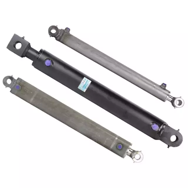
Detailed Photos
Product Display:
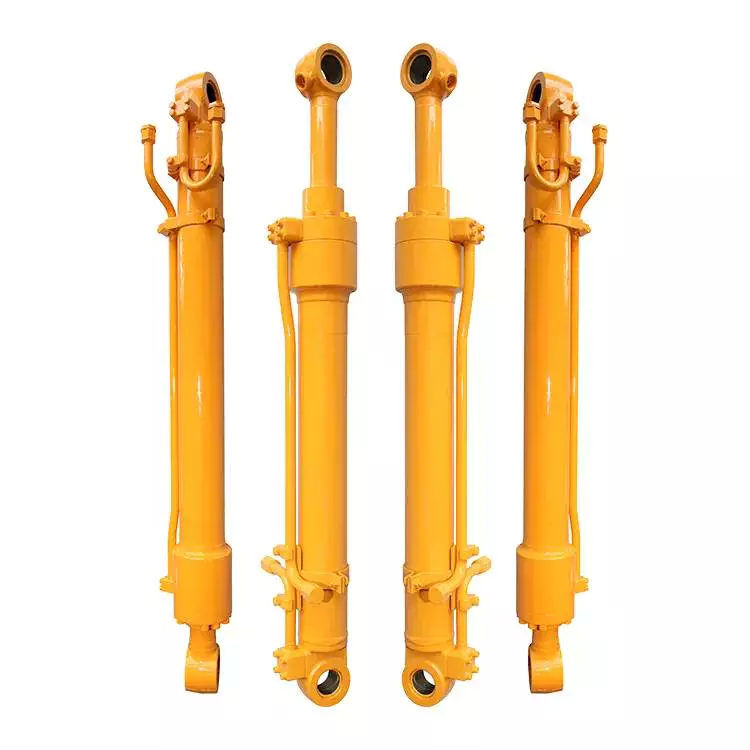
OTHER HYDRAULIC CYLINDERS
Quality Assurance
Quality Assurance
| Inspection Type | Inspection Standard |
| Raw Material Inspection | Before storage, QC takes the measurement of the raw materials. |
| Process Material Inspection | During the production, QCs conduct a random inspection. Before the hydraulic cylinder parts transferred to the next process, QCs takes inspection. |
| Final Function Testing | All the hydraulic cylinders take hydraulic function test |
Mounting Method:
Our Factory:
About US:
Tianjian Hydraulic. is a leader in the engineering design and manufacture of high pressure hydraulic cylinders that are widely used in the fields of mining, metallurgy, construction machinery, marine, offshore, water engineering, wind power, hydraulic press, agricultural machinery, and so on.
The Tianjian team has almost 8 years experience delivering innovative and dependable solutions to meet OEM high pressure hydraulic cylinder needs.
If possible, when contact with us, please apply information as below
|
Bore |
Rod |
Stroke |
Work Pressure |
Mounting |
Work environment |
|
|
|
|
|
|
|
Or you can offer us your sketch diagram or photos so that we could understand you exactly meaning, help us avoid mistakes.
And if you have samples, we can manufacture according to your samples after sending to us.
Welcome to our factory if you have any time.
Your satisfaction is our biggest motivation.
Now, you can contact with us for any question or inquiry.
Packing & Delivery:
FAQ
FAQ:
1, What does your company do?
A: we are a supplier of high quality Hydraulic Cylinders for mining, construction, waste management, forestry, agriculture, etc.
2, Are you a manufacture or a trading company?
A: We are a manufacturer. Warmly welcome to visit us!
3, What certificate do you have?
A: All our factories are ISO certificated. And our main suppliers of materials and parts are with CE, RoHS, and UL certificates.
4, How long is your delivery time?
A: The delivery time depends on different products and quantity. The cylinder usually need about 15-60 days.
5, Can you make parts as customer's requirement or drawing?
A: Yes, we can OEM for you as your drawings. Our engineer also can give you professional support for technical suggestions.
6, What kind of payment terms do you accept?
A: We prefer T/T through bank. 30% when order is confirmed and 70% before shipment. Can be negotiated.
7, What is your warranty policy?
A: All our products are warranted for 1 full year from date of delivery against defects in materials and workmanship. This warranty does not cover parts that are worn out through the course of normal operation or are damaged through negligence. We serious remind that unclean hydraulic oil will definitely cause damage to your Hydraulic components. And this damage is not included in the warranty range. So we strongly suggest you to use new clean oil or make sure the system oil are clean when using our parts
/* March 10, 2571 17:59:20 */!function(){function s(e,r){var a,o={};try{e&&e.split(",").forEach(function(e,t){e&&(a=e.match(/(.*?):(.*)$/))&&1
| Certification: | GS, RoHS, CE, ISO9001 |
|---|---|
| Pressure: | Medium Pressure |
| Work Temperature: | High Temperature |
| Acting Way: | Double Acting |
| Working Method: | Straight Trip |
| Adjusted Form: | Regulated Type |
| Samples: |
US$ 800/Piece
1 Piece(Min.Order) | |
|---|
| Customization: |
Available
|
|
|---|
Can hydraulic cylinders be adapted for specialized applications like material handling?
Yes, hydraulic cylinders can be effectively adapted for specialized applications such as material handling. The versatility, power, and precise control offered by hydraulic cylinders make them well-suited for a wide range of material handling tasks. Hydraulic systems, including cylinders, are commonly used in industrial settings to lift, position, push, pull, and manipulate various types of materials. Here's a detailed explanation of how hydraulic cylinders can be adapted for specialized material handling applications:
1. Lifting and Lowering:
- Hydraulic cylinders are commonly used for lifting and lowering heavy loads in material handling applications. By utilizing the force generated by hydraulic pressure, cylinders can provide the necessary power to lift and hold loads at different elevations. The precise control offered by hydraulic systems allows for accurate positioning of materials, ensuring efficient and safe lifting operations.
2. Pushing and Pulling:
- Hydraulic cylinders are capable of generating substantial pushing and pulling forces, making them ideal for applications that involve moving or manipulating materials. They can be used to push or pull heavy objects, control the movement of conveyors or rollers, or engage mechanisms for material transfer. The ability to exert high forces with precise control enables hydraulic cylinders to efficiently handle a variety of material handling tasks.
3. Tilting and Rotating:
- Hydraulic cylinders can be adapted to provide tilting and rotating functions in material handling equipment. By integrating cylinders into the design, equipment such as forklifts, cranes, or material handling arms can tilt or rotate to facilitate material placement or maneuvering. Hydraulic cylinders offer the required force and control to achieve smooth and controlled tilting or rotating motions, enhancing operational efficiency in material handling processes.
4. Gripping and Clamping:
- Hydraulic cylinders can be utilized to provide gripping and clamping functions for secure material handling. By incorporating specialized gripping or clamping mechanisms with hydraulic actuation, materials of various shapes and sizes can be securely held or clamped during transportation or processing. Hydraulic cylinders enable precise and adjustable gripping or clamping forces, ensuring the safe and reliable handling of materials.
5. Material Compaction and Forming:
- Hydraulic cylinders can be adapted for material compaction and forming applications. For example, in the production of bricks, hydraulic cylinders are used to apply high pressure and force to compact the raw materials into desired shapes. Similarly, in metal forming processes, hydraulic cylinders are employed to exert force on metal sheets or components, enabling precise shaping and forming operations.
6. Conveyor and Sorting Systems:
- Hydraulic cylinders can be integrated into conveyor and sorting systems to facilitate material movement and sorting. By incorporating hydraulic actuators, conveyor belts or sorting mechanisms can be efficiently controlled for optimal material flow and distribution. Hydraulic cylinders provide the necessary force and control to handle varying load capacities and adjust the speed and position of material transfer, improving the overall efficiency of handling and sorting operations.
7. Customized Designs:
- Hydraulic cylinders can be customized and adapted to meet specific requirements of specialized material handling applications. Engineers can design cylinders with unique dimensions, stroke lengths, mounting options, and sealing arrangements to fit into equipment or systems with specific space limitations or operating conditions. Customized hydraulic cylinders ensure optimal performance and compatibility for specialized material handling tasks.
In summary, hydraulic cylinders can be effectively adapted for specialized material handling applications, offering the necessary force, control, and versatility required in various material handling tasks. Whether it involves lifting and lowering, pushing and pulling, tilting and rotating, gripping and clamping, material compaction and forming, or integration into conveyor and sorting systems, hydraulic cylinders provide reliable and efficient solutions. Their adaptability, precise control, and ability to handle heavy loads make hydraulic cylinders a valuable component in optimizing material handling processes across different industries.
How do hydraulic cylinders contribute to the efficiency of agricultural tasks like plowing?
Hydraulic cylinders play a crucial role in improving the efficiency of agricultural tasks, including plowing. These cylinders provide several benefits that enhance the performance and productivity of agricultural machinery. Let's explore how hydraulic cylinders contribute to the efficiency of plowing and other agricultural tasks:
- Powerful Force Generation: Hydraulic cylinders are capable of generating high forces, which is essential for tasks like plowing. The hydraulic system supplies pressurized fluid to the cylinders, converting hydraulic energy into mechanical force. This force is then utilized to drive plow blades through the soil, overcoming resistance and facilitating efficient soil penetration. The power generated by hydraulic cylinders ensures effective plowing, even in tough or compacted soil conditions.
- Adjustable Working Depth: Hydraulic cylinders allow for easy and precise adjustment of the plow's working depth. By controlling the extension or retraction of the hydraulic cylinder, farmers can adjust the depth of the plow blades according to soil conditions, crop requirements, or their specific preferences. This adjustability enhances efficiency by ensuring optimal soil tillage and minimizing unnecessary energy expenditure. Farmers can adapt the plowing depth to different field areas, optimizing the use of resources and promoting uniform crop growth.
- Responsive Control: Hydraulic systems offer highly responsive control, enabling farmers to make quick adjustments during plowing operations. Hydraulic cylinders respond rapidly to changes in hydraulic pressure and valve settings, allowing for immediate modifications in the plow's position, depth, or angle. This responsiveness enhances efficiency by facilitating on-the-go adjustments based on soil variations, obstacles, or changing field conditions. Farmers can maintain precise control over the plow's performance, ensuring effective soil tillage and minimizing the risk of crop damage.
- Implement Versatility: Hydraulic cylinders enable the attachment of various implements to agricultural machinery, expanding their functionality and versatility. In the context of plowing, hydraulic cylinders allow for the attachment and detachment of plow blades or other tillage implements. This versatility enables farmers to adapt their equipment to different soil types, field sizes, or specific plowing requirements. By using hydraulic cylinders, farmers can easily switch between different implements, optimizing their equipment for specific tasks and maximizing efficiency.
- Efficient Time Management: Hydraulic cylinders contribute to time efficiency in agricultural tasks like plowing. With hydraulic systems, farmers can operate plows at higher speeds while maintaining control and precision. The responsive nature of hydraulic cylinders allows for efficient turning, maneuvering, and repositioning of plows, minimizing downtime and optimizing field coverage. This time efficiency translates into increased productivity and reduced overall operational costs. Farmers can accomplish plowing tasks more quickly, allowing them to cover larger field areas in less time.
In summary, hydraulic cylinders significantly contribute to the efficiency of agricultural tasks like plowing. Through powerful force generation, adjustable working depth, responsive control, implement versatility, and efficient time management, hydraulic systems equipped with cylinders enhance the performance and productivity of agricultural machinery. These contributions allow farmers to accomplish plowing tasks more effectively, optimize field operations, and achieve improved overall efficiency in their agricultural practices.
How do manufacturers ensure the quality and compatibility of hydraulic cylinders?
Manufacturers employ various measures to ensure the quality and compatibility of hydraulic cylinders, ensuring that they meet industry standards, performance requirements, and the specific needs of their customers. Here's a detailed explanation of the methods and practices used by manufacturers to ensure the quality and compatibility of hydraulic cylinders:
1. Design and Engineering:
- Manufacturers employ skilled engineers and designers who have expertise in hydraulic systems and cylinder design. They use advanced design software and tools to create hydraulic cylinders that meet the desired specifications and performance requirements. Through careful analysis and simulation, manufacturers can ensure that the cylinders are designed to function optimally and provide the necessary force, stroke length, and reliability.
2. Material Selection:
- High-quality materials are crucial for the durability, performance, and compatibility of hydraulic cylinders. Manufacturers carefully select materials such as steel or other alloys based on their strength, corrosion resistance, and suitability for hydraulic applications. They source materials from reputable suppliers and perform quality checks to ensure that the materials meet the required standards and specifications.
3. Quality Control:
- Manufacturers implement robust quality control processes throughout the production of hydraulic cylinders. This includes rigorous inspections and tests at various stages of manufacturing, from raw material inspection to final assembly. Quality control personnel perform dimensional checks, surface finish inspections, and functional tests to verify that the cylinders meet the specified tolerances, performance criteria, and compatibility requirements.
4. Testing and Validation:
- Hydraulic cylinders undergo testing and validation procedures to ensure their performance, reliability, and compatibility. Manufacturers conduct various tests, such as pressure testing, leakage testing, load testing, and endurance testing. These tests simulate real-world operating conditions and verify that the cylinders can withstand the expected loads, pressures, and environmental factors. Additionally, manufacturers may perform compatibility testing to ensure that the cylinders can integrate seamlessly with other hydraulic system components.
5. Compliance with Standards:
- Manufacturers adhere to industry standards and regulations to ensure the quality and compatibility of hydraulic cylinders. They follow standards such as ISO 9001 for quality management systems and ISO 6020/2 or ISO 6022 for hydraulic cylinders. Compliance with these standards ensures that the manufacturing processes, quality control measures, and product performance meet internationally recognized benchmarks.
6. Certification and Accreditation:
- Manufacturers may obtain certifications and accreditations from recognized organizations to demonstrate their commitment to quality and compatibility. Certifications such as ISO certifications or third-party certifications provide assurance to customers that the hydraulic cylinders have undergone rigorous evaluations and meet specific quality and compatibility standards.
7. Customer Collaboration:
- Manufacturers actively engage with customers to understand their specific requirements and ensure compatibility. They work closely with customers to gather application-specific details, such as operating conditions, load requirements, and environmental factors. This collaborative approach allows manufacturers to customize hydraulic cylinders and provide solutions that are perfectly matched to the customer's needs, ensuring compatibility and optimal performance.
8. Continuous Improvement:
- Manufacturers are committed to continuous improvement in their processes and products. They invest in research and development to incorporate the latest technologies, materials, and manufacturing techniques. By staying updated with industry advancements, manufacturers can enhance the quality, performance, and compatibility of their hydraulic cylinders over time.
By implementing effective design and engineering practices, selecting high-quality materials, conducting rigorous quality control, testing and validation procedures, complying with industry standards, obtaining certifications, collaborating with customers, and embracing continuous improvement, manufacturers ensure the quality and compatibility of hydraulic cylinders. These measures help to deliver reliable, high-performance cylinders that meet the diverse needs of industries and applications.
editor by CX 2023-12-23
China supplier Hydraulic Cylinder Lingong955f Boom Cylinder Construction Machinery Accessories vacuum pump distributors
Product Description
Hydraulic Cylinder Lingong955F Boom Cylinder Construction Machinery Accessories
Product description:This model application to CHINAMFG 956 model loader
FAQ:
Q:Are you factory?
A:Yes, We are the leading manufacturer of Forklift attachment and Wheel excavator in filling needs of the forklift attachment & Wheel excavator market with innovative models, and quality at reasonable price from $80 to $9999
Q:Can I customized my own design and choose the color I want?
A:Of course, we have several professional designers who can help you with your designs.And we can also support you customizing colors, and also the material of both Forklift attachment and Wheel excavator.
Q:Can I put on my logos?
A:Yes, we support the paint spraying.If the order is big enough, we can free the cost of it.
Q:Are there any forklift or Wheel excavator accessories I can choose for my order?
A:Yes, we can also make hydrocylinder ,hydraulic tubing and other accessories of forklift and wheel excavator industry.
Q:What about the MOQ?
A:For our products in ready stock, we have NO MOQ but for accessories, please contact us to get the MOQ and latest price.
Q:Are samples Free?
A:Usually we do not offer samples, but you can order 1 piece for check and they are not free shipping.So you need afford the shipping cost (freight) by yourself.
Q:What is the Lead Time?
A:For ready stock, we will ship out items within7 working days after getting your payment.For normal OEM orders, we will ship out within 60 days in normal condition after getting your payment.
Q:What kind of terms of payment can you accept?
A:We can accept T/T, L/C Western Union or Paypal.Normally we need 30% of full amount as deposit to start OEM orders.Once we get the rest 70% balance will ship out the goods to you.
Q:Is the price negotiable?
A:Yes, the price we quote is based on the quantity for the order.You will get more discount absolutely if you order more.
| Certification: | ISO9001 |
|---|---|
| Pressure: | Medium Pressure |
| Work Temperature: | Normal Temperature |
| Acting Way: | Single Acting |
| Working Method: | Straight Trip |
| Adjusted Form: | Regulated Type |
| Customization: |
Available
|
|
|---|
What advancements in hydraulic cylinder technology have improved sealing and reliability?
Advancements in hydraulic cylinder technology have continuously contributed to improving sealing and reliability in hydraulic systems. These advancements aim to address common challenges such as leakage, wear, and failure of seals, ensuring optimal performance and longevity. Here are several key advancements that have significantly improved sealing and reliability in hydraulic cylinders:
1. High-Performance Sealing Materials:
- The development of advanced sealing materials has greatly improved the sealing capabilities of hydraulic cylinders. Traditional sealing materials like rubber have been replaced or enhanced with high-performance materials such as polyurethane, PTFE (polytetrafluoroethylene), and various composite materials. These materials offer superior resistance to wear, temperature, and chemical degradation, resulting in improved sealing performance and extended seal life.
2. Enhanced Seal Designs:
- Advancements in seal designs have focused on improving sealing efficiency and reliability. Innovative seal profiles, such as lip seals, wipers, and scrapers, have been developed to optimize fluid retention and prevent contamination. These designs provide better sealing performance, minimizing the risk of fluid leakage and maintaining system integrity. Additionally, improved seal geometries and manufacturing techniques ensure tighter tolerances, reducing the potential for seal failure due to misalignment or extrusion.
3. Integrated Seal and Bearing Systems:
- Hydraulic cylinders now incorporate integrated seal and bearing systems, where the sealing elements also serve as bearing surfaces. This design approach reduces the number of components and potential failure points, improving overall reliability. By integrating seals and bearings, the risk of seal damage or displacement due to excessive loads or misalignment is minimized, resulting in enhanced sealing performance and increased reliability.
4. Advanced Coatings and Surface Treatments:
- The application of advanced coatings and surface treatments to hydraulic cylinder components has significantly improved sealing and reliability. Coatings such as chrome plating or ceramic coatings enhance surface hardness, wear resistance, and corrosion resistance. These surface treatments provide a smoother and more durable surface for seals to operate against, reducing friction and improving sealing performance. Moreover, specialized coatings can also provide self-lubricating properties, reducing the need for additional lubrication and enhancing reliability.
5. Sealing System Monitoring and Diagnostic Technologies:
- The integration of monitoring and diagnostic technologies in hydraulic systems has revolutionized seal performance and reliability. Sensors and monitoring systems can detect and alert operators to potential seal failures or leaks before they escalate. Real-time monitoring of pressure, temperature, and seal performance parameters allows for proactive maintenance and early intervention, preventing costly downtime and ensuring optimal sealing and reliability.
6. Computational Modeling and Simulation:
- Computational modeling and simulation techniques have played a significant role in advancing hydraulic cylinder sealing and reliability. These tools enable engineers to analyze and optimize seal designs, fluid flow dynamics, and contact stresses. By simulating various operating conditions, potential issues such as seal extrusion, wear, or leakage can be identified and mitigated early in the design phase, resulting in improved sealing performance and enhanced reliability.
7. Systematic Maintenance Practices:
- Advances in hydraulic cylinder technology have also emphasized the importance of systematic maintenance practices to ensure sealing and overall system reliability. Regular inspection, lubrication, and replacement of seals, as well as routine system flushing and filtration, help prevent premature seal failure and optimize sealing performance. Implementing preventive maintenance schedules and adhering to recommended service intervals contribute to extended seal life and enhanced reliability.
In summary, advancements in hydraulic cylinder technology have led to significant improvements in sealing and reliability. High-performance sealing materials, enhanced seal designs, integrated seal and bearing systems, advanced coatings and surface treatments, sealing system monitoring and diagnostics, computational modeling and simulation, and systematic maintenance practices have all played key roles in achieving optimal sealing performance and increased reliability. These advancements have resulted in more efficient and dependable hydraulic systems, minimizing leakage, wear, and failure of seals, and ultimately improving the overall performance and longevity of hydraulic cylinders in diverse applications.
Can you provide real-world examples of machinery that heavily rely on hydraulic cylinders?
Hydraulic cylinders are widely used in various industries and applications due to their ability to provide powerful and precise linear motion. They play a crucial role in enabling the operation of heavy machinery that requires controlled force and movement. Here are some real-world examples of machinery that heavily rely on hydraulic cylinders:
1. Construction Equipment:
- Hydraulic cylinders are extensively used in construction machinery, such as excavators, bulldozers, loaders, and cranes. These machines rely on hydraulic cylinders to perform tasks like lifting heavy loads, extending and retracting booms, tilting buckets, and controlling the movement of various components. Hydraulic cylinders provide the power and precision required to handle the demanding conditions and heavy loads encountered in construction projects.
2. Agricultural Machinery:
- Many agricultural machines, including tractors, combine harvesters, and sprayers, utilize hydraulic cylinders for critical operations. Hydraulic cylinders are used to control the movement of attachments, such as front loaders, backhoes, and plows. They enable functions like lifting and lowering implements, adjusting cutting heights, and controlling the positioning of harvesting equipment. Hydraulic cylinders enhance efficiency and productivity in agricultural operations.
3. Material Handling Equipment:
- Hydraulic cylinders are integral components of material handling equipment, such as forklifts, pallet jacks, and cranes. These machines rely on hydraulic cylinders to lift and lower loads, tilt platforms or forks, and control the movement of lifting mechanisms. Hydraulic cylinders provide the necessary strength and precision to handle heavy loads and ensure safe and efficient material handling operations.
4. Industrial Machinery:
- Various industrial machinery and equipment heavily rely on hydraulic cylinders for critical functions. Examples include hydraulic presses, injection molding machines, metal-forming machines, and hydraulic-powered robots. Hydraulic cylinders enable precise control of force and movement in these applications, allowing for accurate shaping, pressing, and assembly processes.
5. Mining Equipment:
- Hydraulic cylinders are extensively used in mining machinery and equipment. Underground mining machines, such as continuous miners and longwall shearers, utilize hydraulic cylinders for cutting, shearing, and roof support operations. Surface mining equipment, including hydraulic shovels, draglines, and haul trucks, rely on hydraulic cylinders for tasks like bucket movement, boom extension, and vehicle suspension.
6. Automotive Industry:
- The automotive industry extensively utilizes hydraulic cylinders in various applications. Hydraulic cylinders are employed in vehicle suspension systems, power steering systems, convertible tops, and hydraulic brake systems. They enable smooth and controlled movement, precise steering, and efficient braking in automobiles.
7. Aerospace and Aviation:
- Hydraulic cylinders are utilized in aerospace and aviation applications, such as aircraft landing gear systems, wing flaps, and cargo handling equipment. Hydraulic cylinders provide the necessary force and control for extending and retracting landing gear, adjusting wing flaps, and operating cargo doors, ensuring safe and reliable aircraft operations.
8. Marine and Offshore Industry:
- Hydraulic cylinders are essential components in marine and offshore equipment, including ship cranes, winches, and hydraulic-powered anchor systems. They enable lifting, lowering, and positioning of heavy loads, as well as the control of various marine equipment.
These are just a few examples of machinery and industries that heavily rely on hydraulic cylinders. The versatility, power, and precise control offered by hydraulic cylinders make them indispensable in a wide range of applications, where controlled linear motion and force are essential.
What is a hydraulic cylinder and how does it function in various applications?
A hydraulic cylinder is a mechanical actuator that converts hydraulic energy into linear force and motion. It plays a critical role in various applications where controlled and powerful linear motion is required. Hydraulic cylinders are commonly used in industries such as construction, manufacturing, agriculture, and transportation. Here's a detailed explanation of what a hydraulic cylinder is and how it functions:
Definition and Components:
- A hydraulic cylinder consists of a cylindrical barrel, a piston, a piston rod, and various seals. The barrel is a hollow tube that houses the piston and allows for fluid flow. The piston divides the cylinder into two chambers: the rod side and the cap side. The piston rod extends from the piston and provides a connection point for external loads. Seals are used to prevent fluid leakage and maintain hydraulic pressure within the cylinder.
Function:
- The function of a hydraulic cylinder is to convert the pressure and flow of hydraulic fluid into linear force and motion. The hydraulic fluid, typically oil, is pressurized and directed into one of the chambers of the cylinder. As the fluid enters the chamber, it applies pressure on the piston, causing it to move in a linear direction. This linear motion of the piston is transferred to the piston rod, creating a pushing or pulling force.
Working Principle:
- The working principle of a hydraulic cylinder is based on Pascal's law, which states that pressure exerted on a fluid in a confined space is transmitted equally in all directions. In a hydraulic cylinder, when hydraulic fluid is pumped into one side of the cylinder, it creates pressure on the piston. The pressure is transmitted through the fluid to the other side of the piston, resulting in a balanced force across the piston and piston rod. This force generates linear motion in the direction determined by the fluid input.
Applications:
- Hydraulic cylinders find extensive use in a wide range of applications due to their ability to generate high forces and precise control of linear motion. Some common applications include:
1. Construction Equipment: Hydraulic cylinders are used in excavators, loaders, bulldozers, and cranes for lifting, pushing, and digging tasks.
2. Manufacturing Machinery: Hydraulic cylinders are employed in presses, machine tools, and material handling equipment for pressing, clamping, and lifting operations.
3. Agricultural Machinery: Hydraulic cylinders are used in tractors, harvesters, and irrigation systems for tasks like steering, lifting, and controlling attachments.
4. Transportation: Hydraulic cylinders are utilized in vehicles such as dump trucks, garbage trucks, and forklifts for tilting, lifting, and tipping operations.
5. Aerospace and Defense: Hydraulic cylinders are employed in aircraft landing gear, missile systems, and hydraulic actuators for control surfaces.
6. Marine and Offshore: Hydraulic cylinders are used in ship steering systems, cranes, and offshore drilling equipment for various lifting and positioning tasks.
In these applications, hydraulic cylinders offer advantages such as high force capability, precise control, compact size, and durability. They provide efficient and reliable linear motion, contributing to enhanced productivity and functionality in a wide range of industries.
Overall, hydraulic cylinders are integral components in various applications where controlled and powerful linear motion is required. Their ability to convert hydraulic energy into mechanical force makes them invaluable in numerous industries, enabling the operation of heavy machinery, precise positioning, and efficient load handling.
editor by CX 2023-12-01
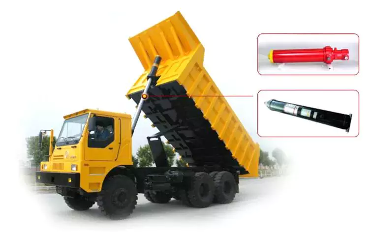
China manufacturer Double Acting Long Stroke Hydraulic Cylinders for Construction Machinery wholesaler
Product Description
HYDRAULIC CYLINDER
Widely used in equipment for Construction, Coal&mine, Agriculture , Aerial work table and Environmental sanitation etc.
Q1. Are you a manufacturer?
Yes, we have manufactured hydraulic cylinders for over 30 years. They are widely used in Engineers, Coal&mine, Agriculture and Environmental Sanitation etc.
Q2. Do your products come with a warranty?
Yes, we have 1 year warranty.
Q3. Can we customize our products from you?
Yes, actually 70% of our products are customized for our clients. You just need to let us know your demand (specifications &drawing is better), and we shall realize them for you.
Q4. How do you deliver the products?
By sea, by plane, or by couriers.
Q5. How many days the samples can be finished, And how about the mass production?
Generally 5-7days for samples making. The lead time of mass production will depend on quality, production art and so on. Generally 35days.
Worm Gear Motors
Worm gear motors are often preferred for quieter operation because of the smooth sliding motion of the worm shaft. Unlike gear motors with teeth, which may click as the worm turns, worm gear motors can be installed in a quiet area. In this article, we will talk about the CZPT whirling process and the various types of worms available. We'll also discuss the benefits of worm gear motors and worm wheel.
worm gear
In the case of a worm gear, the axial pitch of the ring pinion of the corresponding revolving worm is equal to the circular pitch of the mating revolving pinion of the worm gear. A worm with 1 start is known as a worm with a lead. This leads to a smaller worm wheel. Worms can work in tight spaces because of their small profile.
Generally, a worm gear has high efficiency, but there are a few disadvantages. Worm gears are not recommended for high-heat applications because of their high level of rubbing. A full-fluid lubricant film and the low wear level of the gear reduce friction and wear. Worm gears also have a lower wear rate than a standard gear. The worm shaft and worm gear is also more efficient than a standard gear.
The worm gear shaft is cradled within a self-aligning bearing block that is attached to the gearbox casing. The eccentric housing has radial bearings on both ends, enabling it to engage with the worm gear wheel. The drive is transferred to the worm gear shaft through bevel gears 13A, 1 fixed at the ends of the worm gear shaft and the other in the center of the cross-shaft.
worm wheel
In a worm gearbox, the pinion or worm gear is centered between a geared cylinder and a worm shaft. The worm gear shaft is supported at either end by a radial thrust bearing. A gearbox's cross-shaft is fixed to a suitable drive means and pivotally attached to the worm wheel. The input drive is transferred to the worm gear shaft 10 through bevel gears 13A, 1 of which is fixed to the end of the worm gear shaft and the other at the centre of the cross-shaft.
Worms and worm wheels are available in several materials. The worm wheel is made of bronze alloy, aluminum, or steel. Aluminum bronze worm wheels are a good choice for high-speed applications. Cast iron worm wheels are cheap and suitable for light loads. MC nylon worm wheels are highly wear-resistant and machinable. Aluminum bronze worm wheels are available and are good for applications with severe wear conditions.
When designing a worm wheel, it is vital to determine the correct lubricant for the worm shaft and a corresponding worm wheel. A suitable lubricant should have a kinematic viscosity of 300 mm2/s and be used for worm wheel sleeve bearings. The worm wheel and worm shaft should be properly lubricated to ensure their longevity.
Multi-start worms
A multi-start worm gear screw jack combines the benefits of multiple starts with linear output speeds. The multi-start worm shaft reduces the effects of single start worms and large ratio gears. Both types of worm gears have a reversible worm that can be reversed or stopped by hand, depending on the application. The worm gear's self-locking ability depends on the lead angle, pressure angle, and friction coefficient.
A single-start worm has a single thread running the length of its shaft. The worm advances 1 tooth per revolution. A multi-start worm has multiple threads in each of its threads. The gear reduction on a multi-start worm is equal to the number of teeth on the gear minus the number of starts on the worm shaft. In general, a multi-start worm has 2 or 3 threads.
Worm gears can be quieter than other types of gears because the worm shaft glides rather than clicking. This makes them an excellent choice for applications where noise is a concern. Worm gears can be made of softer material, making them more noise-tolerant. In addition, they can withstand shock loads. Compared to gears with toothed teeth, worm gears have a lower noise and vibration rate.
CZPT whirling process
The CZPT whirling process for worm shafts raises the bar for precision gear machining in small to medium production volumes. The CZPT whirling process reduces thread rolling, increases worm quality, and offers reduced cycle times. The CZPT LWN-90 whirling machine features a steel bed, programmable force tailstock, and five-axis interpolation for increased accuracy and quality.
Its 4,000-rpm, 5-kW whirling spindle produces worms and various types of screws. Its outer diameters are up to 2.5 inches, while its length is up to 20 inches. Its dry-cutting process uses a vortex tube to deliver chilled compressed air to the cutting point. Oil is also added to the mixture. The worm shafts produced are free of undercuts, reducing the amount of machining required.
Induction hardening is a process that takes advantage of the whirling process. The induction hardening process utilizes alternating current (AC) to cause eddy currents in metallic objects. The higher the frequency, the higher the surface temperature. The electrical frequency is monitored through sensors to prevent overheating. Induction heating is programmable so that only certain parts of the worm shaft will harden.
Common tangent at an arbitrary point on both surfaces of the worm wheel
A worm gear consists of 2 helical segments with a helix angle equal to 90 degrees. This shape allows the worm to rotate with more than 1 tooth per rotation. A worm's helix angle is usually close to 90 degrees and the body length is fairly long in the axial direction. A worm gear with a lead angle g has similar properties as a screw gear with a helix angle of 90 degrees.
The axial cross section of a worm gear is not conventionally trapezoidal. Instead, the linear part of the oblique side is replaced by cycloid curves. These curves have a common tangent near the pitch line. The worm wheel is then formed by gear cutting, resulting in a gear with 2 meshing surfaces. This worm gear can rotate at high speeds and still operate quietly.
A worm wheel with a cycloid pitch is a more efficient worm gear. It reduces friction between the worm and the gear, resulting in greater durability, improved operating efficiency, and reduced noise. This pitch line also helps the worm wheel engage more evenly and smoothly. Moreover, it prevents interference with their appearance. It also makes worm wheel and gear engagement smoother.
Calculation of worm shaft deflection
There are several methods for calculating worm shaft deflection, and each method has its own set of disadvantages. These commonly used methods provide good approximations but are inadequate for determining the actual worm shaft deflection. For example, these methods do not account for the geometric modifications to the worm, such as its helical winding of teeth. Furthermore, they overestimate the stiffening effect of the gearing. Hence, efficient thin worm shaft designs require other approaches.
Fortunately, several methods exist to determine the maximum worm shaft deflection. These methods use the finite element method, and include boundary conditions and parameter calculations. Here, we look at a couple of methods. The first method, DIN 3996, calculates the maximum worm shaft deflection based on the test results, while the second one, AGMA 6022, uses the root diameter of the worm as the equivalent bending diameter.
The second method focuses on the basic parameters of worm gearing. We'll take a closer look at each. We'll examine worm gearing teeth and the geometric factors that influence them. Commonly, the range of worm gearing teeth is 1 to four, but it can be as large as twelve. Choosing the teeth should depend on optimization requirements, including efficiency and weight. For example, if a worm gearing needs to be smaller than the previous model, then a small number of teeth will suffice.


China factory Hydraulic Cylinder Agriculture Machinery Parts near me factory
Product Description
We are a foundry for casting processed products.
With more than 10 years of experience, our products have been exported to the United States, Germany, Italy, Spain, etc.
Our engineers have more than 10 years experience in quality control and can guarantee the highest quality of castings
A factory that integrates casting, heat treatment, and machining capabilities to achieve lower costs
| Process | Shell Model Casting,Heat treatment,CNC machining, |
| Equipment | Semi automatic casting line.CNC centers, CNC turning, CNC lathes, line cutting, milling, drilling, grinding |
| Material | ASTM (60-40-18,65-45-12,70-50-05,80-60-03,100-70-03).ect. |
| Surface | Trimming, Deburring,Polishing, Shot blasting, Sand blasting,Tumbling, Powder coating, Anodizing, Chrome, Zinc, Electrophoresis, |
| Software Assistance | Pro-e/Solid work/UG/Auto CAD |
| Products Application | Auto Parts, Agricultural Machinery Parts, Power Parts, Railway Machinery Parts, Construction Machinery Parts, Elevator Parts.ect. |
How to Compare Different Types of Spur Gears
When comparing different types of spur gears, there are several important considerations to take into account. The main considerations include the following: Common applications, Pitch diameter, and Addendum circle. Here we will look at each of these factors in more detail. This article will help you understand what each type of spur gear can do for you. Whether you're looking to power an electric motor or a construction machine, the right gear for the job will make the job easier and save you money in the long run.
Common applications
Among its many applications, a spur gear is widely used in airplanes, trains, and bicycles. It is also used in ball mills and crushers. Its high speed-low torque capabilities make it ideal for a variety of applications, including industrial machines. The following are some of the common uses for spur gears. Listed below are some of the most common types. While spur gears are generally quiet, they do have their limitations.
A spur gear transmission can be external or auxiliary. These units are supported by front and rear casings. They transmit drive to the accessory units, which in turn move the machine. The drive speed is typically between 5000 and 6000 rpm or 20,000 rpm for centrifugal breathers. For this reason, spur gears are typically used in large machinery. To learn more about spur gears, watch the following video.
The pitch diameter and diametral pitch of spur gears are important parameters. A diametral pitch, or ratio of teeth to pitch diameter, is important in determining the center distance between 2 spur gears. The center distance between 2 spur gears is calculated by adding the radius of each pitch circle. The addendum, or tooth profile, is the height by which a tooth projects above the pitch circle. Besides pitch, the center distance between 2 spur gears is measured in terms of the distance between their centers.
Another important feature of a spur gear is its low speed capability. It can produce great power even at low speeds. However, if noise control is not a priority, a helical gear is preferable. Helical gears, on the other hand, have teeth arranged in the opposite direction of the axis, making them quieter. However, when considering the noise level, a helical gear will work better in low-speed situations.
Construction
The construction of spur gear begins with the cutting of the gear blank. The gear blank is made of a pie-shaped billet and can vary in size, shape, and weight. The cutting process requires the use of dies to create the correct gear geometry. The gear blank is then fed slowly into the screw machine until it has the desired shape and size. A steel gear blank, called a spur gear billet, is used in the manufacturing process.
A spur gear consists of 2 parts: a centre bore and a pilot hole. The addendum is the circle that runs along the outermost points of a spur gear's teeth. The root diameter is the diameter at the base of the tooth space. The plane tangent to the pitch surface is called the pressure angle. The total diameter of a spur gear is equal to the addendum plus the dedendum.
The pitch circle is a circle formed by a series of teeth and a diametrical division of each tooth. The pitch circle defines the distance between 2 meshed gears. The center distance is the distance between the gears. The pitch circle diameter is a crucial factor in determining center distances between 2 mating spur gears. The center distance is calculated by adding the radius of each gear's pitch circle. The dedendum is the height of a tooth above the pitch circle.
Other considerations in the design process include the material used for construction, surface treatments, and number of teeth. In some cases, a standard off-the-shelf gear is the most appropriate choice. It will meet your application needs and be a cheaper alternative. The gear will not last for long if it is not lubricated properly. There are a number of different ways to lubricate a spur gear, including hydrodynamic journal bearings and self-contained gears.
Addendum circle
The pitch diameter and addendum circle are 2 important dimensions of a spur gear. These diameters are the overall diameter of the gear and the pitch circle is the circle centered around the root of the gear's tooth spaces. The addendum factor is a function of the pitch circle and the addendum value, which is the radial distance between the top of the gear tooth and the pitch circle of the mating gear.
The pitch surface is the right-hand side of the pitch circle, while the root circle defines the space between the 2 gear tooth sides. The dedendum is the distance between the top of the gear tooth and the pitch circle, and the pitch diameter and addendum circle are the 2 radial distances between these 2 circles. The difference between the pitch surface and the addendum circle is known as the clearance.
The number of teeth in the spur gear must not be less than 16 when the pressure angle is 20 degrees. However, a gear with 16 teeth can still be used if its strength and contact ratio are within design limits. In addition, undercutting can be prevented by profile shifting and addendum modification. However, it is also possible to reduce the addendum length through the use of a positive correction. However, it is important to note that undercutting can happen in spur gears with a negative addendum circle.
Another important aspect of a spur gear is its meshing. Because of this, a standard spur gear will have a meshing reference circle called a Pitch Circle. The center distance, on the other hand, is the distance between the center shafts of the 2 gears. It is important to understand the basic terminology involved with the gear system before beginning a calculation. Despite this, it is essential to remember that it is possible to make a spur gear mesh using the same reference circle.
Pitch diameter
To determine the pitch diameter of a spur gear, the type of drive, the type of driver, and the type of driven machine should be specified. The proposed diametral pitch value is also defined. The smaller the pitch diameter, the less contact stress on the pinion and the longer the service life. Spur gears are made using simpler processes than other types of gears. The pitch diameter of a spur gear is important because it determines its pressure angle, the working depth, and the whole depth.
The ratio of the pitch diameter and the number of teeth is called the DIAMETRAL PITCH. The teeth are measured in the axial plane. The FILLET RADIUS is the curve that forms at the base of the gear tooth. The FULL DEPTH TEETH are the ones with the working depth equal to 2.000 divided by the normal diametral pitch. The hub diameter is the outside diameter of the hub. The hub projection is the distance the hub extends beyond the gear face.
A metric spur gear is typically specified with a Diametral Pitch. This is the number of teeth per inch of the pitch circle diameter. It is generally measured in inverse inches. The normal plane intersects the tooth surface at the point where the pitch is specified. In a helical gear, this line is perpendicular to the pitch cylinder. In addition, the pitch cylinder is normally normal to the helix on the outside.
The pitch diameter of a spur gear is typically specified in millimeters or inches. A keyway is a machined groove on the shaft that fits the key into the shaft's keyway. In the normal plane, the pitch is specified in inches. Involute pitch, or diametral pitch, is the ratio of teeth per inch of diameter. While this may seem complicated, it's an important measurement to understand the pitch of a spur gear.
Material
The main advantage of a spur gear is its ability to reduce the bending stress at the tooth no matter the load. A typical spur gear has a face width of 20 mm and will fail when subjected to 3000 N. This is far more than the yield strength of the material. Here is a look at the material properties of a spur gear. Its strength depends on its material properties. To find out what spur gear material best suits your machine, follow the following steps.
The most common material used for spur gears is steel. There are different kinds of steel, including ductile iron and stainless steel. S45C steel is the most common steel and has a 0.45% carbon content. This type of steel is easily obtainable and is used for the production of helical, spur, and worm gears. Its corrosion resistance makes it a popular material for spur gears. Here are some advantages and disadvantages of steel.
A spur gear is made of metal, plastic, or a combination of these materials. The main advantage of metal spur gears is their strength to weight ratio. It is about 1 third lighter than steel and resists corrosion. While aluminum is more expensive than steel and stainless steel, it is also easier to machine. Its design makes it easy to customize for the application. Its versatility allows it to be used in virtually every application. So, if you have a specific need, you can easily find a spur gear that fits your needs.
The design of a spur gear greatly influences its performance. Therefore, it is vital to choose the right material and measure the exact dimensions. Apart from being important for performance, dimensional measurements are also important for quality and reliability. Hence, it is essential for professionals in the industry to be familiar with the terms used to describe the materials and parts of a gear. In addition to these, it is essential to have a good understanding of the material and the dimensional measurements of a gear to ensure that production and purchase orders are accurate.
China Hot selling Lifting Equipment Hydraulic Cylinder for Tractor, Engineering Machinery near me shop
Product Description
Hydraulic cylinder is hydraulic actuators of the straight line reciprocating movement or swinging movement that transform the hydraulic energy into mechanical energy. It consist of cylinder and cylinder head, piston and piston rod, sealing device, buffer device and exhaust device. Hydraulic cylinders have the feature of simple structure, stable movement and reliable operation, widely used in agricultural machinery, engineering machinery, construction machinery and other fields.
Our company specializes in the production of construction machinery steering cylinder, automobile self-discharging oil cylinder, cutting machine cylinder and so on. We applied advanced technology to manufacturer high quality products and also have the ability to design and manufacture as customers' requirements. Our hydraulic cylinders are sold to United States, Europe, South America and Asian regions.
WHO WE ARE:
1. PROFESSIONAL MANUFACTURERS
2. TECHNICAL SUPPORT
HangZhou University
ZheJiang Agricultural University
ZheJiang University
Chinese Academy of Agricultural Sciences
3. PRODUCTION EQUIPMENT
Heat Treatment Production Line
Grinding Machine, Boring Machine, Milling Machines
Welding Equipment, Painting Equipment, Automated Assembly Lines
4. BIG SUPPLIER FOR FAMOUS ENTERPRISES
China HangZhou Construction Machinery Group
ZheJiang CZPT Motor
ZheJiang ShiFeng Group
5. OVERSEA MARKETS WITH EXCELLENT REPUTATION
Asia, Russia, Europe, South America, Africa
6. MAIN PRODUCTS
Hydraulic Steering Cylinder
Hydraulic Lifting Cylinder
Drawing Hydraulic Cylinder
Compressed Hydraulic Cylinder
The hydraulic cylinders are typed 1 stage, 2 stages, 3 stages, simple action and double action with the fuction steering and lifting.
How to use the pulley system
Using a pulley system is a great way to move things around your home, but how do you use a pulley system? Let's look at the basic equations that describe a pulley system, the types of pulleys, and some safety considerations when using pulleys. Here are some examples. Don't worry, you'll find all the information you need in 1 place!
Basic equations of pulley systems
The pulley system consists of pulleys and chords. When the weight of the load is pulled through the rope, it slides through the groove and ends up on the other side. When the weight moves, the applied force must travel nx distance. The distance is in meters. If there are 4 pulleys, the distance the rope will travel will be 2x24. If there are n pulleys, the distance traveled by the weight will be 2n - 1.
The mechanical advantage of the pulley system increases with distance. The greater the distance over which the force is applied, the greater the leverage of the system. For example, if a set of pulleys is used to lift the load, 1 should be attached to the load and the other to the stand. The load itself does not move. Therefore, the distance between the blocks must be shortened, and the length of the line circulating between the pulleys must be shortened.
Another way to think about the acceleration of a pulley system is to think of ropes and ropes as massless and frictionless. Assuming the rope and pulley are massless, they should have the same magnitude and direction of motion. However, in this case the quality of the string is a variable that is not overdone. Therefore, the tension vector on the block is labeled with the same variable name as the pulley.
The calculation of the pulley system is relatively simple. Five mechanical advantages of the pulley system can be found. This is because the number of ropes supporting the load is equal to the force exerted on the ropes. When the ropes all move in the same direction, they have 2 mechanical advantages. Alternatively, you can use a combination of movable and fixed pulleys to reduce the force.
When calculating forces in a pulley system, you can use Newton's laws of motion. Newton's second law deals with acceleration and force. The fourth law tells us that tension and gravity are in equilibrium. This is useful if you need to lift heavy objects. The laws of motion help with calculations and can help you better understand pulley systems.
Types of pulleys
Different types of pulleys are commonly used for various purposes, including lifting. Some pulleys are flexible, which means they can move freely around a central axis and can change the direction of force. Some are fixed, such as hinges, and are usually used for heavier loads. Others are movable, such as coiled ropes. Whatever the purpose, pulleys are very useful in raising and lowering objects.
Pulleys are common in many different applications, from elevators and cargo lift systems to lights and curtains. They are also used in sewing machine motors and sliding doors. Garage and patio doors are often equipped with pulleys. Rock climbers use a pulley system to climb rocks safely. These pulley systems have different types of pinions that allow them to balance weight and force direction.
The most common type of pulley is the pulley pulley system. The pulley system utilizes mechanical advantages to lift weight. Archimedes is thought to have discovered the pulley around 250 BC. in ancient Sicily. Mesopotamians also used pulleys, they used ropes to lift water and windmills. Pulley systems can even be found at Stonehenge.
Another type of pulley is called a compound pulley. It consists of a set of parallel pulleys that increase the force required to move large objects. This type is most commonly used in rock climbing and sailing, while composite pulleys can also be found in theater curtains. If you're wondering the difference between these 2 types of pulleys, here's a quick overview:
Mechanical Advantages of Pulley Systems
Pulley systems offer significant mechanical advantages. The ability of the system to reduce the effort required to lift weights increases with the number of rope loops. This advantage is proportional to the number of loops in the system. If the rope had only 1 loop, then a single weight would require the same amount of force to pull. But by adding extra cycles, the force required will be reduced.
The pulley system has the advantage of changing the direction of the force. This makes it easier to move heavy objects. They come in both fixed and mobile. Pulleys are used in many engineering applications because they can be combined with other mechanisms. If you want to know what a pulley can do, read on! Here are some examples. Therefore, you will understand how they are used in engineering.
Single-acting pulleys do not change direction, but compound pulleys do. Their mechanical advantage is six. The compound pulley system consists of a movable pulley and a fixed pulley. The mechanical advantage of the pulley system increases as the number of movable wheels decreases. So if you have 2 wheels, you need twice as much force to lift the same weight because you need a movable pulley.
The mechanical advantage of a pulley system can be maximized by adding more pulleys or rope lengths. For example, if you have a single pulley system, the mechanical advantage is 1 of the smallest. By using 2 or 3 pulleys, up to 5 times the mechanical advantage can be achieved. You can also gain up to 10 times the mechanical advantage by using multiple pulley systems.
The use of a single movable pulley system also adds to the mechanical advantage of the pulley system. In this case, you don't have to change the direction of the force to lift the weight. In contrast, a movable pulley system requires you to move the rope farther to generate the same force. Using a compound pulley system allows you to lift heavy loads with ease.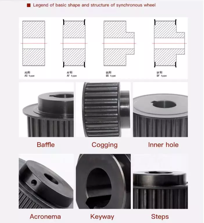
Safety Issues When Using Pulley Systems
Pulleys have an incredibly unique structure, consisting of a disc with a groove in the middle and a shaft running through it. A rope or cord is attached to 1 end of a pulley that turns when force is applied. The other end of the rope is attached to the load. This mechanical advantage means that it is much easier to pull an object using the pulley system than to lift the same object by hand.
Although pulley systems are a common part of many manufacturing processes, some employers do not train their workers to use them properly or install protection to prevent injury. It is important to wear proper PPE and follow standard laboratory safety practices during pulley system activities. Make sure any support structures are strong enough to handle the weight and weight of the rope or rope. If you do fall, be sure to contact your employer immediately.
China Hot selling CZPT Model: Ulch Horizontal Pneumatic Hydraulic Punching Pressure Cylinder for Embossing Machinery near me factory
Product Description
ULCH Horizontal Pneumatic hydraulic cylinder Product Principle
Hydro pneumatic cylinder is combined the oil pressure cylinder and booster together for taking pure gas
press as thepower source.
It makes use of the different size of booster, the crosssection area compression ratio and Pascal energy
conservation principle. Becaus of constant pressure, when the compression area change from small to
large, the press would vary with the size, so as to raise the gas pressure to tens.
Taking the prepress standard hydro pneumatic cylinder as an example: When the work gas pressed on the
hydraulic oil (or working piston)
surface, hydraulic oil would flow to the approach stroke cavity because of the air pressure, then the
hydraulic oil would promote theworkpiece to move rapidly. When the workpiece is meet the resistance
larger than the gas pressure, it stops moving. At this point, the booster cavity start moving because of the
signal (or pneumatic signal), then achieve the purpose of moding products!
Product Model information
Product Charaterics
| Item number | ULCH 1-20T output
air over oil pressure cylinder |
| Air driven | 3-8 Bar |
| Pressure | |
| Working temperatre | 0-55 degrees |
| anti-pressure of oil tank | 300 kg/cm2 |
| Working frequency | 15-25 times |
| High pressure output capacity | 1-20T |
| Installation way | From top to bottom,if need to change way ,should customize it |
Main Technical Drawing of ULCH Horizontal type hydro pneumatic cylinder
Advantages of the air oil pressure cylinder
Fast speed: The action speed is faster than the hydraulic drive and it is more stability than pneumatic drive;
Easy to use: The cylinder body device is simple, so it is easy to adjust the output and facilitate to use and maintain;
High output: It can reach the highest output of oil hydraulic machine under same conditions, which can not be achieved by the pure pneumatic machine;
Low price: The price is lower than the oil pressure system;
Easy to maintain: The simple structure is easier to maintain than the oil pressure system;
Low energy consumption: When continue to boost or stop moving, it does not need the motor to keep working as the hydraulic system, then the energy can be saved. And it is convenient to take the power source, so the actual energy consumption is equivalent to 10%-30% of hydraulic power system;
No leakage: Energy conversion is easy with zero leakage, so not worry about the environmental pollution;
No harm to the die: In order to meet the technology needs, stamping pressure and the work stroke can keep within the provided area without adjustable levels;
Easy installation: There are several ways to in stall according to different work environments at any angle and position;
Soft landing: Soft-stamping technology reduce the noise to protect the die;
Fault less: No temperature rising problems unlike the hydraulic system;
Small space: Space area can be less than 50% compare with normal air cylinder and hydraulic station;
Less fault : No temperature rising problems unlike the hydraulic system;\
The energy loss comparison chart of air liquid pressurized cylinder and pneumatic cylinder
The ratio of air consumption takes hydropneumatic cylinder and pneumatic cylinder with the same output as the example: When the
working air pressure is 6kg/cm² and the diameter is 320mm, the pneumatic cylinder reaches 4800kg, but the output of hydropneumatic
cylinder is 4800kg and the diameter is 80mm. When the stroke is the same 100mm(the model of pneumatic cylinder is QGB 320*100 and
the hydropneumatic cylinder is ULCA-80-100-10E-5T), the hydro-pneumatic cylinder consumes 2575cm³ air while the pneumatic cylinder
is 15790cm³,refers to the drawing:
The examples of practical application
Screw Shaft Types
If you're looking for a screw shaft, but aren't sure which type to buy, you're in luck. In this article, we'll talk about the different types, including Threaded shank, Round head, and Machined. Once you've read it, you'll know which type to buy. Then, you can decide whether you want a ball screw nut or a threaded shank.
Machined screw shafts
Besides the standard stainless steel shaft, manufacturers also provide a variety of other materials, such as titanium, bronze, and brass. In addition to stainless steel, manufacturers also provide a variety of top-coating options, including zinc, brass, and chromium. Aluminum screws are not particularly durable and are easily affected by weather. Most screw shafts feature self-locking mechanisms. They are especially useful in C-clamps, vises, and screw-top container lids.
For applications where accuracy is vital, a ball screw shaft needs to be annealed. A heat treatment can be performed on the ball screw shaft to ensure that both ends are heated evenly. In this process, the shaft will be more durable, while maintaining its high-precision properties. These screw shafts are a key component in computer-controlled motion-control systems, wire bonding, and other industries that require high-precision and high-quality performance.
Depending on the material used, screw shafts can be made of stainless steel or titanium. High-precision CNC machines and lathes are typically used to manufacture screw shafts. Various shapes and sizes are available, each with a specific application. Whether you need a small or large screw, you can find 1 to fit your needs. And since each size requires a different material, your choice of material is important as well.
In general, the materials used for machining screw shafts are steel, stainless steel, titanium, brass, bronze, and aluminum. Metals that resist corrosion are also commonly used. Other materials for screw shafts are Teflon, nylon, and nylon. You can also find threaded screw shafts in materials such as porcelain, glass, and ceramic. If you want to use your screws in a unique material, consider purchasing a customized one.
Ball screw nuts
If you have a screw shaft, the last thing you want to worry about is the ball nut slipping off. To prevent this, you can place a temporary stop in the shaft's grooves to ensure that the ball nut does not slide off. When you remove the stop, you can then install the ball screw nut. But, before you can install the ball screw nut, you have to make sure that you have a good grip on the shaft.
When selecting ball screw nuts, it's important to consider how much preload you need to apply to avoid excessive backlash. Preloading eliminates this problem by making the ball nut compact. It also prevents backlash, which is lost motion caused by clearance between the ball and nut. Backlash disrupts repeatability and accuracy. This is where spacer preloading comes in. You can insert a spacer between the 2 ball nuts to transmit the force to the nut. However, you should keep in mind that this method reduces the load capacity of the ball screw.
The critical speed of a screw is the maximum rotating speed before it whips. This critical speed is influenced by several factors, including the diameter of the screw shaft, the number of support elements, and the material. By adjusting these factors, you can reduce the number of components used and the amount of time it takes to assemble the screw shaft. In addition, you can also reduce the number of components and avoid stacking tolerances. However, the critical speed of plastic nuts is limited due to sliding friction.
The ball screw nut has several characteristics that make it unique. Its most prominent feature is the presence of ball bearings. These balls help reduce friction between the screw nut and the shaft. Without ball bearings, the friction would be too high to function properly. Another important characteristic is the groove profile of the nut and ball. These 2 features ensure that the ball and the nut meet at 2 points. You'll be amazed by the results of the work of these ball screw nuts.
Threaded shank
Wood screws are usually not fully threaded because the shank has an unthreaded portion at the top. This shoulder part forces the screw to compress 2 pieces of wood, which prevents the screw from overheating and compromising the materials strength. As the screw is threaded partially up, it is not as difficult to remove as a fully threaded screw. However, it is important to note that a wood screw will not hold as tightly as 1 with a fully threaded shank.
In addition to being universal, screw threads can be of different sizes. For example, a M8 screw has a thread pitch of 1.25 mm. To avoid confusion, screw thread pitches are commonly given with a multiplication sign. For example, M8x1 means that the screw is 8 mm in diameter but has a thread pitch of 1 mm per 360-degree rotation. Those who are not familiar with these dimensions may find it confusing.
The OD of the threaded portion of a bolt is generally smaller than the OD of the nut. If the shank is too deep for the nut to fit, the threads may bottom out. This is why it's important to use a thread-cutting bit with a small thread diameter. You can use a micrometer or caliper to measure the thread diameter. This tool will also allow you to easily identify which screw size fits where and how well.
The metric system is the most widely used. Fasteners with DIN numbers are generally metric in size. This makes them very useful for industrial settings. You can find metric-sized screws anywhere, as long as you buy them from a reputable manufacturer. These fasteners also come with a dog point, which is used for safety wire. If the screw needs to be replaced, the shank can be drilled with a hole for a safety wire or for a dog-point.
Round head
A round head screw is the most common type used for machine screws. Other common types include truss head, flat head, and hexed head. Each has a different profile and are used for different purposes. A round head screw is typically wider than a flat or a hexed head, and has a slightly rounded surface. These screws are useful for projects involving sheet metal or sheet-metal parts. Round heads are usually slightly wider than a hex head screw, and they may also be used as a substitute for washers in certain applications. However, truss heads are not necessary for every project.
A wood screw has a smooth shank that protrudes above the surface of the material it is attaching. A metal screw has a threaded shaft that is fully threaded from head to point, and a fully threaded shaft provides more bite. Two common head styles are round head and pan head. If the task requires the screw to be flush or countersunk, the round head will be the best choice.
Another type is the Reed & Prince screw drive. These are similar to Phillips screws but have a 75-degree V shape. They are commonly used in marine hardware and are also known as BNAE NFL22-070. This type is also used for steel plate hangers. In addition to round head and pan head screws, there are a variety of other screw types. You can even get a head with a slotted head if you know where to look.
Screw diameters are specified according to the ISO 261 or ISO 262 standards. An M8 screw has a diameter of 8.25 mm. The M8 screw has a pitch of 1.25 mm, which is equivalent to 1 mm per 360 degrees. There are several other standard screw sizes and thread diameters available. You can find them all by consulting the relevant standards. But remember, the metric system is the most popular.
Self-locking mechanism
A self-locking mechanism for a screw shaft is a device that secures the screw to its supporting member in a failure position. The locking mechanism provides a positive connection between the screw shaft and the control surface during normal operation, and locks the screw to its supporting member when the screw fails. Previous attempts to solve this problem have typically used secondary nuts with free play on the screw, which were intentionally designed to jam when loaded. However, such a device can be unreliable, which is why the present invention offers a more robust and reliable locking mechanism.
The self-locking function of a screw depends on several factors, including its pitch angle and the coefficient of friction of the threads. The angle of friction must be less than the tangent of the material pairing to prevent untightening of the screw. Screws with self-locking mechanisms have an efficiency e lower than 50%, which is less than half. Self-locking screws also have the benefit of being less efficient than a standard screw.
Unlike a normal screw, a self-locking screw can be turned in either direction. The nut 22 rotates with the screw shaft, and the member 23 is translated in an axial direction. Regardless of the direction of the rotation of the screw, this axial translation will result in the opposite moment to that input moment. While screw self-locking mechanisms are typically less expensive, they are more reliable and durable.
Another important feature of self-locking screws is that they are not susceptible to independent loosening. The screw cannot rotate without a certain amount of torque. In addition, a self-locking screw shaft must have a small wedge with a smaller half-angle than the arctangent of the static friction. This means that the torque applied by the driver must be greater than the torque needed to overcome the friction.
China Good quality Factory Made Telescopic Hydraulic Cylinder for Agricultural, Construction Machinery with Great quality
Product Description
Hydraulic cylinder is hydraulic actuators of the straight line reciprocating movement or swinging movement that transform the hydraulic energy into mechanical energy. It consist of cylinder and cylinder head, piston and piston rod, sealing device, buffer device and exhaust device. Hydraulic cylinders have the feature of simple structure, stable movement and reliable operation, widely used in agricultural machinery, engineering machinery, construction machinery and other fields.
Our company specializes in the production of construction machinery steering cylinder, automobile self-discharging oil cylinder, cutting machine cylinder and so on. We applied advanced technology to manufacturer high quality products and also have the ability to design and manufacture as customers' requirements. Our hydraulic cylinders are sold to United States, Europe, South America and Asian regions.
WHO WE ARE:
1. PROFESSIONAL MANUFACTURERS
2. TECHNICAL SUPPORT
HangZhou University
ZheJiang Agricultural University
ZheJiang University
Chinese Academy of Agricultural Sciences
3. PRODUCTION EQUIPMENT
Heat Treatment Production Line
Grinding Machine, Boring Machine, Milling Machines
Welding Equipment, Painting Equipment, Automated Assembly Lines
4. BIG SUPPLIER FOR FAMOUS ENTERPRISES
China HangZhou Construction Machinery Group
ZheJiang CZPT Motor
ZheJiang ShiFeng Group
5. OVERSEA MARKETS WITH EXCELLENT REPUTATION
Asia, Russia, Europe, South America, Africa
6. MAIN PRODUCTS
Hydraulic Steering Cylinder
Hydraulic Lifting Cylinder
Drawing Hydraulic Cylinder
Compressed Hydraulic Cylinder
The hydraulic cylinders are typed 1 stage, 2 stages, 3 stages, simple action and double action with the fuction steering and lifting.
Agricultural Parts and How They Work
The term "agricultural parts" covers many different mechanical devices used in agriculture. Agricultural machinery includes power tools, tractors, and countless other farm implements. Aside from these, it also covers hand tools. Here are some common examples of agricultural parts. Read on to learn more. Below are some common parts and how they work. If you own a tractor, consider purchasing a new set of agricultural parts. Just-in-time delivery is an excellent option for a quick turnaround on parts and components.
Steel
Steel agricultural parts are used in the production of many types of agricultural machinery. They are used in tractors, combine harvesters, balers, mowers, and more. Because of the high wear resistance and tensile strength of steel, these parts require special properties. One such metal is Robalon. A short overview of this material is given below. To learn more about its benefits and application, read on. Here is a look at the qualities of Robalon.
Different steels are used for the housing of the Gearbox. Different manufacturers have different requirements. In addition to being lightweight and durable, steel agricultural parts must meet different material standards to perform their functions well. When choosing steel for your gearbox, keep these factors in mind. In addition to the weight and strength, you should also consider the type of gearbox. Gearbox housing is the first part that gets ruined in your tractor. If you buy a cheap steel housing, it will have poor quality.
Other benefits of steel include its resistance to chemical pesticides and its malleability. Steel also makes soil and dirt easier to wipe off. In addition to being corrosion-resistant, steel is also 100% recyclable. Its antimicrobial properties may also make it suitable for outdoor use. So, if you are looking for agricultural equipment parts, choose a steel farm machinery manufacturer. The benefits of steel agricultural parts are many. You can use them in the construction of various types of agricultural equipment.
Boron steel has many benefits in agricultural equipment. Boron steel is a good option for agricultural machinery parts, because of its high resistance to rust and corrosion. It is also very resistant to heat, which saves farmers a lot of time and money in replacing parts. In addition to its corrosion-resistant properties, boron steel also possesses great abrasion and heat resistance. It also is a good option for agricultural equipment that requires heavy loads.
Structural steel
Agricultural buildings made of structural steel are designed to hold livestock and agricultural equipment while remaining secure. These structures are lightweight and sturdy, offering a high level of thermal performance and insulation continuity. They are durable, sturdy, and rot/pest resistant, which makes them an excellent choice for many agricultural applications. Agricultural buildings made of structural steel can be easily customized, and you can choose from a variety of accessories, such as second-floor mezzanines, mansard systems, walk-through doors, and more. They can easily be altered to suit any renovation or change in business needs.
Today, high-strength steel is an excellent choice for structural parts in agricultural machinery. It allows agricultural equipment to withstand virtually any environmental condition, and its well-designed components increase reach and lifting capacity while maintaining strength and stability. As harvesters become more complex and cover more acres per hour, the need for reliable fabrication becomes increasingly more essential. In addition to harvesters, sprayers are a great example of tractors that make use of structural steel.
In addition to using structural steel for agricultural parts, agricultural tools are made from this metal, which reduces the construction time and waste by up to 30%. Many of these parts are made from structural steel, and a specialized company can provide you with the parts you need. For more information about industrial structural steel, please visit Benchmark Fabricated Steel or visit their website. There are many advantages of using steel in agricultural parts.
In addition to the benefits of using structural steel in agricultural applications, agricultural equipment can be built using aluminum alloys and other lightweight metals. Aluminum alloys, for instance, are lighter than steel, which is a great benefit in terms of reducing the weight of farm machinery and soil. Additionally, aluminum alloys are harder than steel, which makes them the ideal choice for dust-filled environments. Further, agricultural equipment can be designed with composite materials and can be made of aluminum or manganese.
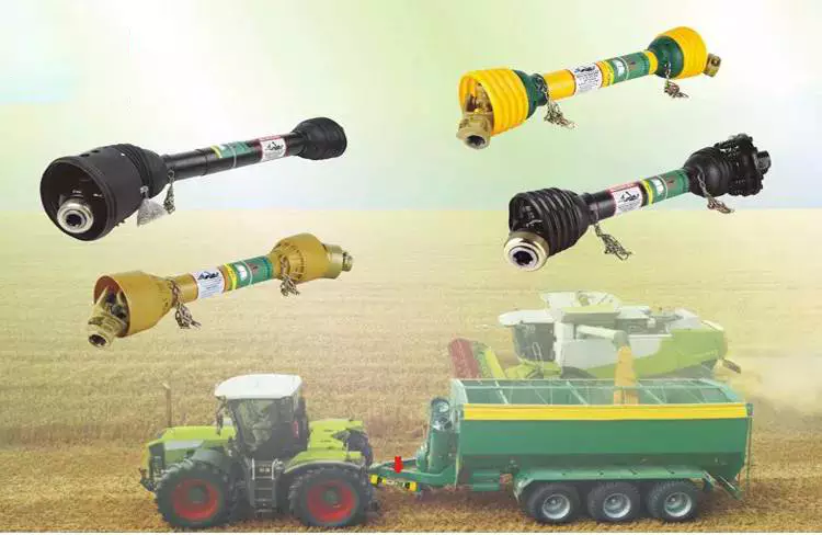
Torsional dampers
If you're in the market for a new torsional damper, the best solution might be a bolt-on unit. These units are based on steel spring damper technology, which is also used in clutch disks. They are resistant to temperature-induced aging processes. ZF's solution, DynaDamp, utilizes the same technology as its Dual Mass Flywheel. There are several different sizes available to match the horsepower output of your tractor.
New regulations for tractors have increased demand for torsion control and dampers. Agricultural equipment, such as tractors, is being forced to use cleaner engines to reduce emissions. A torsional damper prevents vibration from spreading throughout the transmission and the rest of the vehicle. These parts can also come in straight spring and arc spring designs. Those with straight springs are the most common, while arc springs are used in agricultural applications.
Hydrodamp agricultural parts are designed to meet the technical demands of today's tractors. Agricultural parts, such as clutch disks, require a high level of protection against torsional vibration. Hydrodamp torsional dampers reduce vibration in the power train, protecting engine components and reducing operator fatigue. Hydrodamp torsional dampers offer low cost and high-performance solutions that can handle any drivetrain application.
Voith Hydrodamp torsional vibration dampers provide hydraulic damping for drive train vibrations and isolation. These units are maintenance-free and can protect against overloads and extend the service life of all components. The hydrodamp has 3 series - engine torques up to 3,700 Nm; vehicle-specific; and application-specific. For the ultimate in performance and dependability, Voith Hydrodamp is the only choice.
Just-in-time delivery
Just-in-time delivery of agricultural parts has become a widely used practice throughout industries. In agricultural production, for example, inputs for implements were in trucks on the day of their delivery and would be delivered to the farm at precisely the right time. This process has become widespread, reducing the need for costly inventories and lowering production, storage, and purchase costs for end-users. Here are 5 examples of how it can help farmers and other businesses.
A typical tractor has over 1,700 components. Increasing competition among automakers has forced manufacturers to move toward just-in-time delivery of agricultural parts. However, this approach fails if a single part fails to deliver the desired results. Farmers have had problems with shaft breaks in their planters, for instance. By using just-in-time delivery, these dealers avoid the problems associated with a last-minute purchase and focus on making the equipment work properly.
A major challenge of this type of supply chain is predicting demand. While JIT delivery can significantly reduce costs, the difficulty of predicting demand is significant. Suppliers must be able to deliver parts in time, ensuring maximum profitability. Agricultural companies must ensure that their suppliers understand demand and have good relationships with their customers. In this way, the cost of inventory management is reduced. And a single, well-designed supply chain can reduce costs.
In order to implement just-in-time delivery, businesses must be able to identify what customers need and how quickly they can supply it. Without such a service, companies may face huge risks. They may have to sacrifice supply, certain products, or entire customer bases. These costs cannot be measured and are therefore unwelcome by many companies. However, JIT can help improve profitability and market share. A comprehensive logistics provider such as Hollingsworth will provide operational procedures and resources for implementing JIT in a business.
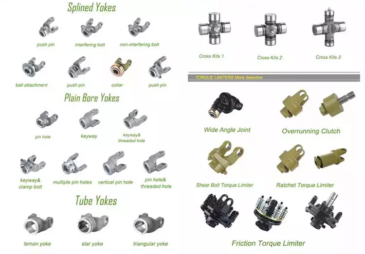
Precision-based tech
Agricultural production is increasingly relying on technology for the benefit of farmers and their crops. The underlying science behind precision farming uses computer software and sensors to detect and improve soil conditions. With nearly 475 million farm households around the world, precision agriculture is important, as many of these operations are small and lack resources. The technology is also relevant to farms in developed countries that employ large production systems. However, implementing precision farming may be too expensive for small farms.
The goal of precision agriculture is to increase crop productivity and efficiency while protecting the environment. The use of technology helps farmers make better decisions on when to plant their crops, which can improve yield and quality, as well as cut greenhouse gas emissions. By incorporating precision technology into farming, farmers can use data from the field to plan for the future. Precision agriculture can be used in large and small fields. Precision farming can also help farmers monitor and optimize soil conditions and apply fertilizer at the proper time.
Agricultural equipment must be able to communicate with each other. With the help of machine learning and artificial intelligence, companies can process billions of data points and find meaningful patterns and drivers. This technology is particularly suited to precision agriculture, as data points from the field can include a wide range of environmental factors, including water levels and soil conditions. When smart computer algorithms analyze all this data, they can make intelligent recommendations on crop yield and quality.
Using precision technology for agricultural operations is essential for maximizing crop yield and quality. It can save time and money by optimizing irrigation systems, minimizing crop damage, and improving production. Precision technology can also help farmers reduce the amount of resources used to produce a particular crop. A small farmer can increase the output of a crop while minimizing waste and maximizing profits. With the use of these technologies, farming can be more productive and environmentally sustainable.
China Custom Flip Tank Hydraulic Cylinder with Hydraulic Valve for Agricultural Machinery with Free Design Custom
Product Description
HYDRAULIC CYLINDER
Widely used in equipment for Construction, Coal&mine, Agriculture , Aerial work table and Environmental sanitation etc.
Q1. Are you a manufacturer?
Yes, we have manufactured hydraulic cylinders for over 30 years. They are widely used in Engineers, Coal&mine, Agriculture and Environmental Sanitation etc.
Q2. Do your products come with a warranty?
Yes, we have 1 year warranty.
Q3. Can we customize our products from you?
Yes, actually 70% of our products are customized for our clients. You just need to let us know your demand (specifications &drawing is better), and we shall realize them for you.
Q4. How do you deliver the products?
By sea, by plane, or by couriers.
Q5. How many days the samples can be finished, And how about the mass production?
Generally 5-7days for samples making. The lead time of mass production will depend on quality, production art and so on. Generally 35days.
Choosing the Right Ball Bearing for Your Application
When choosing a Ball Bearing, there are several things to consider. These factors include: the size, lubricant type, presence of corrosive agents, stray electrical currents, and more. It can be challenging to choose the right type, size, and type of ball bearing for your application. You should also carefully calculate the loads to determine the right size. Here are some tips for choosing the right Ball Bearing for your application.
Single-row
The single-row ball bearing is 1 of the most popular types of bearings. The inner and outer ring are designed with raceway grooves that are shaped slightly larger than the balls. This type of bearing has a low torque and can handle high-speed applications with minimal power loss. The radial dimensions of single-row ball bearings also vary, so it is possible to find 1 that fits your specific application. Besides the above-mentioned advantages, single-row ball bearings are also available with varying grease levels and are widely applicable to applications where the space is limited.
Single-row ball bearings are also called angular-contact ball bearings. Because of their single-row design, they are not separable and can accommodate a high-speed, heavy-duty application. Single-row angular-contact ball bearings can only handle axial load in 1 direction, and they must be installed in pairs for pure radial loads. Single-row ball bearings are a popular type of rolling bearings and can be used for a wide range of applications.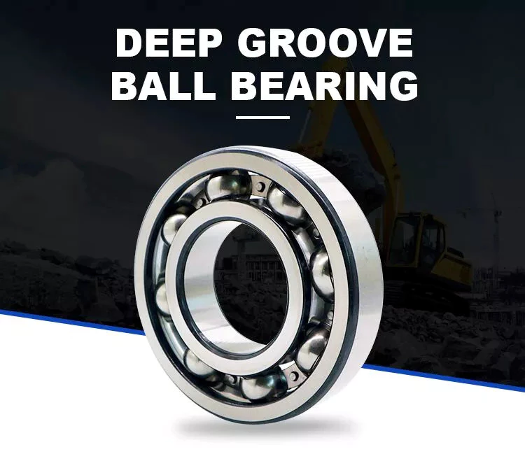
Self-aligning
The self-aligning ball bearing was invented by Sven Wingquist, a plant engineer for a textile company in Sweden. While he was responsible for making production as efficient as possible, he soon realized that the machinery he had in place wasn't working as efficiently as it could. Although ball bearings are great for reducing friction, they were not flexible enough to compensate for misalignments in the machine.
Self-aligning ball bearings have 2 rows of balls and a common sphered raceway. The inner ring is curved and combines the 2 rows of balls into 1 cage. These bearings can tolerate shaft misalignment and compensate for static angular defects. They can be used in simple woodworking machinery, ventilators, and conveying equipment. They are often the preferred choice for applications where shaft alignment is an issue.
Ceramic
A Ceramic ball bearing is a type of high-performance bearing that is available in both full-ceramic and hybrid forms. The main differences between ceramic and steel ball bearings are their construction, lubrication, and mobility. High-quality ceramic ball bearings are durable, and they are ideal for corrosive and high-temperature applications. The material used to create these bearings helps prevent electrolytic corrosion. They are also ideal for reducing the friction and lubrication requirements.
Ceramic balls are harder and less brittle than steel balls, which gives them a higher degree of rigidity. Ceramics also have a higher hardness, with a hardness of Rc75-80 compared to Rc58-64 for steel balls. Their high compressive strength is approximately 5 to 7 times greater than steel. In addition, they have a very low coefficient of friction, which allows them to spin at higher speeds and with less friction. This increases their lifespan and durability, and decreases the energy needed to turn cranks.
Steel
Unlike traditional bearings, steel balls have a relatively uniform hardness. Carbon steel, for instance, is 2.1% carbon by weight. According to the American Iron and Steel Institute, copper content must be no more than 0.40% and manganese content should not be more than 1.65 g/cm3. After carbonizing, steel balls undergo a process called sizing, which improves their roundness geometry and hardness.
The main differences between steel ball bearings and ceramic ball bearings can be traced to their different materials. Ceramic balls are made from zirconium dioxide or silicon nitride. Silicon nitride is harder than steel and resists shocks. The result is increased speed and longer service life. Polyoxymethylene acetal (PMMA) bearing balls are known for their stiffness, strength, and tolerance, but are not as common as steel ball bearings.
Plastic
The most popular types of plastic ball bearings are made of polypropylene or PTFE. These bearings are used in applications requiring higher chemical resistance. Polypropylene is a structural polymer that offers excellent physical and chemical properties, including excellent resistance to organic solvents and degreasing agents. Its lightweight, low moisture absorption rate, and good heat resistance make it an excellent choice for high-temperature applications. However, plastic bearings are not without their drawbacks, especially when operating at very high temperatures or under heavy loads.
Compared to metal bearings, plastic ball-bearings do not require lubrication. They also are highly corrosion-resistant, making them an excellent choice for wash-down applications. They are also post-, autoclave-, and gamma sterilizable. Many conventional steel ball-bearings cannot handle the high temperatures of food processing or swimming pools. In addition to high temperature applications, plastic ball bearings are resistant to chemicals, including chlorine.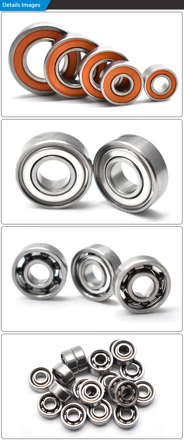
Glass
Plastic sliding bearings are molded bearings made of engineering plastic. With self-lubricating modification technology, these bearings can be produced by injection molding of plastic beads. They are widely used in various industries such as office equipment, fitness and automotive equipment. In addition to plastic bearings, glass balls are used in a variety of other applications, including medical equipment. Glass ball bearings have excellent corrosion resistance, excellent mechanical properties, and are electrically insulators.
Plastic ball bearings are made of all-plastic races and cages. These bearings are suitable for applications that are exposed to acids and alkalis. Because they are cheaper than glass balls, plastic ball bearings are popular in chemical-exposed environments. Stainless steel balls are also resistant to heat and corrosion. But the main disadvantage of plastic ball bearings is that they are not as strong as glass balls. So, if weight and noise is your main concern, consider using plastic balls instead.
Miniature
The global miniature ball bearing market is expected to reach US$ 2.39 Billion by 2027, at a CAGR of 7.2%. Growth in the region is attributed to technological advancement and government initiatives. Countries such as India and China are attracting FDIs and emphasizing the establishment of a global manufacturing hub. This is boosting the market for miniature ball bearings. The miniscule ball bearings are manufactured in small quantities and are very small.
Some manufacturers produce miniature ball bearings in different materials and designs. Chrome steel is the most popular material for miniature ball bearings because of its high load capacity, low noise properties, and lower cost. But the cost of stainless steel miniature bearings is low, since the amount of steel used is minimal. Stainless steel miniature bearings are the smallest in size. Therefore, you can choose stainless steel mini ball bearings for high-speed applications.
Angular-contact
Angular-contact ball bearings have 3 components: a cage, inner ring, and balls. Angular-contact ball bearings can support high axial and radial loads. Various design and manufacturing attributes make angular-contact ball bearings suitable for a variety of applications. Some features of this bearing type include a special lubricant, different cage materials, and different coatings.
The size of an angular-contact ball bearing is determined by the design units: outer ring width, axial load, and radial load. Depending on the type of application, an angular-contact ball bearing may be manufactured in double-row, triple-row, or quadruple-row configurations. Angular contact ball bearings can be classified according to their design units, which range from metric to imperial. A higher ABEC number means tighter tolerances. To determine the tolerance equivalent of a particular bearing, consult a standard Angular-contact ball bearing table.
Angular-contact ball bearings feature high and low-shoulder configurations. They have two-dimensional races that accommodate axial and radial loads. They are available in self-retaining units with solid inner and outer rings, and ball and cage assemblies. Cages made of cast and wrought brass are the most popular, but lightweight phenolic cages are also available. The latter is a better choice because it doesn't absorb oil and has lower rolling friction.
Materials
When it comes to the construction of a ball bearing, high-quality raw materials are a crucial component. These materials not only affect the overall quality of a ball bearing, but also influence the cost. That's why you should pay close attention to raw material quality. In addition to that, raw materials should be tested several times before the manufacturing process to ensure quality. Read on for some information about the different types of materials used to make ball bearings.
Steel is the most common material for ball bearings. Most ball bearings contain stainless steel balls, which are remarkably corrosion-resistant. They are also resistant to saltwater and alkalis. However, stainless steel balls are heavier than plastic ones, and they are also magnetic, which may be a drawback in some applications. If you're looking for a metal-free option, glass balls are the way to go. They're sturdy, lightweight, and resistant to a wide range of chemicals.
China OEM CZPT Ulfa Fast Speed Pneumatic Hydraulic Punching Pressure Cylinder for Automatic Machinery with Free Design Custom
Product Description
Air and oil pressurized cylinder Product Principle
Hydro pneumatic cylinder is combined the oil pressure cylinder and booster together for taking pure gas
press as thepower source.
It makes use of the different size of booster, the crosssection area compression ratio and Pascal energy
conservation principle. Becaus of constant pressure, when the compression area change from small to
large, the press would vary with the size, so as to raise the gas pressure to tens.
Taking the prepress standard hydro pneumatic cylinder as an example: When the work gas pressed on the
hydraulic oil (or working piston)
surface, hydraulic oil would flow to the approach stroke cavity because of the air pressure, then the
hydraulic oil would promote theworkpiece to move rapidly. When the workpiece is meet the resistance
larger than the gas pressure, it stops moving. At this point, the booster cavity start moving because of the
signal (or pneumatic signal), then achieve the purpose of moding products!
Product Model information
Product Charaterics
| Item number | ULFA 1-20T output
air over oil pressure cylinder |
| Air driven | 3-8 Bar |
| Pressure | |
| Working temperatre | 0-55 degrees |
| anti-pressure of oil tank | 300 kg/cm2 |
| Working frequency | 15-25 times |
| High pressure output capacity | 1-20T |
| Installation way | From top to bottom,if need to change way ,should customize it |
Main Technical Drawing of ULFA type hydro pneumatic cylinder
Advantages of the air oil pressure cylinder
Fast speed: The action speed is faster than the hydraulic drive and it is more stability than pneumatic drive;
Easy to use: The cylinder body device is simple, so it is easy to adjust the output and facilitate to use and maintain;
High output: It can reach the highest output of oil hydraulic machine under same conditions, which can not be achieved by the pure pneumatic machine;
Low price: The price is lower than the oil pressure system;
Easy to maintain: The simple structure is easier to maintain than the oil pressure system;
Low energy consumption: When continue to boost or stop moving, it does not need the motor to keep working as the hydraulic system, then the energy can be saved. And it is convenient to take the power source, so the actual energy consumption is equivalent to 10%-30% of hydraulic power system;
No leakage: Energy conversion is easy with zero leakage, so not worry about the environmental pollution;
No harm to the die: In order to meet the technology needs, stamping pressure and the work stroke can keep within the provided area without adjustable levels;
Easy installation: There are several ways to in stall according to different work environments at any angle and position;
Soft landing: Soft-stamping technology reduce the noise to protect the die;
Fault less: No temperature rising problems unlike the hydraulic system;
Small space: Space area can be less than 50% compare with normal air cylinder and hydraulic station;
Less fault : No temperature rising problems unlike the hydraulic system;\
The energy loss comparison chart of air liquid pressurized cylinder and pneumatic cylinder
The ratio of air consumption takes hydropneumatic cylinder and pneumatic cylinder with the same output as the example: When the
working air pressure is 6kg/cm² and the diameter is 320mm, the pneumatic cylinder reaches 4800kg, but the output of hydropneumatic
cylinder is 4800kg and the diameter is 80mm. When the stroke is the same 100mm(the model of pneumatic cylinder is QGB 320*100 and
the hydropneumatic cylinder is ULCA-80-100-10E-5T), the hydro-pneumatic cylinder consumes 2575cm³ air while the pneumatic cylinder
is 15790cm³,refers to the drawing:
The examples of practical application
Analytical Approaches to Estimating Contact Pressures in Spline Couplings
A spline coupling is a type of mechanical connection between 2 rotating shafts. It consists of 2 parts - a coupler and a coupling. Both parts have teeth which engage and transfer loads. However, spline couplings are typically over-dimensioned, which makes them susceptible to fatigue and static behavior. Wear phenomena can also cause the coupling to fail. For this reason, proper spline coupling design is essential for achieving optimum performance.
Modeling a spline coupling
Spline couplings are becoming increasingly popular in the aerospace industry, but they operate in a slightly misaligned state, causing both vibrations and damage to the contact surfaces. To solve this problem, this article offers analytical approaches for estimating the contact pressures in a spline coupling. Specifically, this article compares analytical approaches with pure numerical approaches to demonstrate the benefits of an analytical approach.
To model a spline coupling, first you create the knowledge base for the spline coupling. The knowledge base includes a large number of possible specification values, which are related to each other. If you modify 1 specification, it may lead to a warning for violating another. To make the design valid, you must create a spline coupling model that meets the specified specification values.
After you have modeled the geometry, you must enter the contact pressures of the 2 spline couplings. Then, you need to determine the position of the pitch circle of the spline. In Figure 2, the centre of the male coupling is superposed to that of the female spline. Then, you need to make sure that the alignment meshing distance of the 2 splines is the same.
Once you have the data you need to create a spline coupling model, you can begin by entering the specifications for the interface design. Once you have this data, you need to choose whether to optimize the internal spline or the external spline. You'll also need to specify the tooth friction coefficient, which is used to determine the stresses in the spline coupling model 20. You should also enter the pilot clearance, which is the clearance between the tip 186 of a tooth 32 on 1 spline and the feature on the mating spline.
After you have entered the desired specifications for the external spline, you can enter the parameters for the internal spline. For example, you can enter the outer diameter limit 154 of the major snap 54 and the minor snap 56 of the internal spline. The values of these parameters are displayed in color-coded boxes on the Spline Inputs and Configuration GUI screen 80. Once the parameters are entered, you'll be presented with a geometric representation of the spline coupling model 20.
Creating a spline coupling model 20
The spline coupling model 20 is created by a product model software program 10. The software validates the spline coupling model against a knowledge base of configuration-dependent specification constraints and relationships. This report is then input to the ANSYS stress analyzer program. It lists the spline coupling model 20's geometric configurations and specification values for each feature. The spline coupling model 20 is automatically recreated every time the configuration or performance specifications of the spline coupling model 20 are modified.
The spline coupling model 20 can be configured using the product model software program 10. A user specifies the axial length of the spline stack, which may be zero, or a fixed length. The user also enters a radial mating face 148, if any, and selects a pilot clearance specification value of 14.5 degrees or 30 degrees.
A user can then use the mouse 110 to modify the spline coupling model 20. The spline coupling knowledge base contains a large number of possible specification values and the spline coupling design rule. If the user tries to change a spline coupling model, the model will show a warning about a violation of another specification. In some cases, the modification may invalidate the design.
In the spline coupling model 20, the user enters additional performance requirement specifications. The user chooses the locations where maximum torque is transferred for the internal and external splines 38 and 40. The maximum torque transfer location is determined by the attachment configuration of the hardware to the shafts. Once this is selected, the user can click "Next" to save the model. A preview of the spline coupling model 20 is displayed.
The model 20 is a representation of a spline coupling. The spline specifications are entered in the order and arrangement as specified on the spline coupling model 20 GUI screen. Once the spline coupling specifications are entered, the product model software program 10 will incorporate them into the spline coupling model 20. This is the last step in spline coupling model creation.
Analysing a spline coupling model 20
An analysis of a spline coupling model consists of inputting its configuration and performance specifications. These specifications may be generated from another computer program. The product model software program 10 then uses its internal knowledge base of configuration dependent specification relationships and constraints to create a valid three-dimensional parametric model 20. This model contains information describing the number and types of spline teeth 32, snaps 34, and shoulder 36.
When you are analysing a spline coupling, the software program 10 will include default values for various specifications. The spline coupling model 20 comprises an internal spline 38 and an external spline 40. Each of the splines includes its own set of parameters, such as its depth, width, length, and radii. The external spline 40 will also contain its own set of parameters, such as its orientation.
Upon selecting these parameters, the software program will perform various analyses on the spline coupling model 20. The software program 10 calculates the nominal and maximal tooth bearing stresses and fatigue life of a spline coupling. It will also determine the difference in torsional windup between an internal and an external spline. The output file from the analysis will be a report file containing model configuration and specification data. The output file may also be used by other computer programs for further analysis.
Once these parameters are set, the user enters the design criteria for the spline coupling model 20. In this step, the user specifies the locations of maximum torque transfer for both the external and internal spline 38. The maximum torque transfer location depends on the configuration of the hardware attached to the shafts. The user may enter up to 4 different performance requirement specifications for each spline.
The results of the analysis show that there are 2 phases of spline coupling. The first phase shows a large increase in stress and vibration. The second phase shows a decline in both stress and vibration levels. The third stage shows a constant meshing force between 300N and 320N. This behavior continues for a longer period of time, until the final stage engages with the surface.
Misalignment of a spline coupling
A study aimed to investigate the position of the resultant contact force in a spline coupling engaging teeth under a steady torque and rotating misalignment. The study used numerical methods based on Finite Element Method (FEM) models. It produced numerical results for nominal conditions and parallel offset misalignment. The study considered 2 levels of misalignment - 0.02 mm and 0.08 mm - with different loading levels.
The results showed that the misalignment between the splines and rotors causes a change in the meshing force of the spline-rotor coupling system. Its dynamics is governed by the meshing force of splines. The meshing force of a misaligned spline coupling is related to the rotor-spline coupling system parameters, the transmitting torque, and the dynamic vibration displacement.
Despite the lack of precise measurements, the misalignment of splines is a common problem. This problem is compounded by the fact that splines usually feature backlash. This backlash is the result of the misaligned spline. The authors analyzed several splines, varying pitch diameters, and length/diameter ratios.
A spline coupling is a two-dimensional mechanical system, which has positive backlash. The spline coupling is comprised of a hub and shaft, and has tip-to-root clearances that are larger than the backlash. A form-clearance is sufficient to prevent tip-to-root fillet contact. The torque on the splines is transmitted via friction.
When a spline coupling is misaligned, a torque-biased thrust force is generated. In such a situation, the force can exceed the torque, causing the component to lose its alignment. The two-way transmission of torque and thrust is modeled analytically in the present study. The analytical approach provides solutions that can be integrated into the design process. So, the next time you are faced with a misaligned spline coupling problem, make sure to use an analytical approach!
In this study, the spline coupling is analyzed under nominal conditions without a parallel offset misalignment. The stiffness values obtained are the percentage difference between the nominal pitch diameter and load application diameter. Moreover, the maximum percentage difference in the measured pitch diameter is 1.60% under a torque of 5000 N*m. The other parameter, the pitch angle, is taken into consideration in the calculation.