Tag Archives: hydraulic cylinder engineering

China Professional Engineering Hydraulic Oil Cylinder with Great quality

Product Description

HYDRAULIC PRESS, CYLINDERS & POWER PACKS.

Our hydraulic press machines includes:
2500T hydraulic cold press machines,
2500T cold extruding hydraulic press,
3500T cold forging hydraulic press machines,
Four-column hydraulic press machine series,
Frame type hydraulic cold press machine series,
Metal powder forming hydraulic press
Cookware making hydraulic cold press
Ceramic hydraulic press, Ceramic powder molding press machines
Hydraulic press for gears, bearings, and other special items.
We also supply:
Hydraulic cylinders
Hydraulic power packs
Please offer us the technical data of your hydraulic press machines, cylinders or power packs. We could make them to your purpose.
 

Spiral Gears for Right-Angle Right-Hand Drives

Spiral gears are used in mechanical systems to transmit torque. The bevel gear is a particular type of spiral gear. It is made up of 2 gears that mesh with 1 another. Both gears are connected by a bearing. The 2 gears must be in mesh alignment so that the negative thrust will push them together. If axial play occurs in the bearing, the mesh will have no backlash. Moreover, the design of the spiral gear is based on geometrical tooth forms.
Gear

Equations for spiral gear

The theory of divergence requires that the pitch cone radii of the pinion and gear be skewed in different directions. This is done by increasing the slope of the convex surface of the gear's tooth and decreasing the slope of the concave surface of the pinion's tooth. The pinion is a ring-shaped wheel with a central bore and a plurality of transverse axes that are offset from the axis of the spiral teeth.
Spiral bevel gears have a helical tooth flank. The spiral is consistent with the cutter curve. The spiral angle b is equal to the pitch cone's genatrix element. The mean spiral angle bm is the angle between the genatrix element and the tooth flank. The equations in Table 2 are specific for the Spread Blade and Single Side gears from Gleason.
The tooth flank equation of a logarithmic spiral bevel gear is derived using the formation mechanism of the tooth flanks. The tangential contact force and the normal pressure angle of the logarithmic spiral bevel gear were found to be about 20 degrees and 35 degrees respectively. These 2 types of motion equations were used to solve the problems that arise in determining the transmission stationary. While the theory of logarithmic spiral bevel gear meshing is still in its infancy, it does provide a good starting point for understanding how it works.
This geometry has many different solutions. However, the main 2 are defined by the root angle of the gear and pinion and the diameter of the spiral gear. The latter is a difficult 1 to constrain. A 3D sketch of a bevel gear tooth is used as a reference. The radii of the tooth space profile are defined by end point constraints placed on the bottom corners of the tooth space. Then, the radii of the gear tooth are determined by the angle.
The cone distance Am of a spiral gear is also known as the tooth geometry. The cone distance should correlate with the various sections of the cutter path. The cone distance range Am must be able to correlate with the pressure angle of the flanks. The base radii of a bevel gear need not be defined, but this geometry should be considered if the bevel gear does not have a hypoid offset. When developing the tooth geometry of a spiral bevel gear, the first step is to convert the terminology to pinion instead of gear.
The normal system is more convenient for manufacturing helical gears. In addition, the helical gears must be the same helix angle. The opposite hand helical gears must mesh with each other. Likewise, the profile-shifted screw gears need more complex meshing. This gear pair can be manufactured in a similar way to a spur gear. Further, the calculations for the meshing of helical gears are presented in Table 7-1.
Gear

Design of spiral bevel gears

A proposed design of spiral bevel gears utilizes a function-to-form mapping method to determine the tooth surface geometry. This solid model is then tested with a surface deviation method to determine whether it is accurate. Compared to other right-angle gear types, spiral bevel gears are more efficient and compact. CZPT Gear Company gears comply with AGMA standards. A higher quality spiral bevel gear set achieves 99% efficiency.
A geometric meshing pair based on geometric elements is proposed and analyzed for spiral bevel gears. This approach can provide high contact strength and is insensitive to shaft angle misalignment. Geometric elements of spiral bevel gears are modeled and discussed. Contact patterns are investigated, as well as the effect of misalignment on the load capacity. In addition, a prototype of the design is fabricated and rolling tests are conducted to verify its accuracy.
The 3 basic elements of a spiral bevel gear are the pinion-gear pair, the input and output shafts, and the auxiliary flank. The input and output shafts are in torsion, the pinion-gear pair is in torsional rigidity, and the system elasticity is small. These factors make spiral bevel gears ideal for meshing impact. To improve meshing impact, a mathematical model is developed using the tool parameters and initial machine settings.
In recent years, several advances in manufacturing technology have been made to produce high-performance spiral bevel gears. Researchers such as Ding et al. optimized the machine settings and cutter blade profiles to eliminate tooth edge contact, and the result was an accurate and large spiral bevel gear. In fact, this process is still used today for the manufacturing of spiral bevel gears. If you are interested in this technology, you should read on!
The design of spiral bevel gears is complex and intricate, requiring the skills of expert machinists. Spiral bevel gears are the state of the art for transferring power from 1 system to another. Although spiral bevel gears were once difficult to manufacture, they are now common and widely used in many applications. In fact, spiral bevel gears are the gold standard for right-angle power transfer.While conventional bevel gear machinery can be used to manufacture spiral bevel gears, it is very complex to produce double bevel gears. The double spiral bevel gearset is not machinable with traditional bevel gear machinery. Consequently, novel manufacturing methods have been developed. An additive manufacturing method was used to create a prototype for a double spiral bevel gearset, and the manufacture of a multi-axis CNC machine center will follow.
Spiral bevel gears are critical components of helicopters and aerospace power plants. Their durability, endurance, and meshing performance are crucial for safety. Many researchers have turned to spiral bevel gears to address these issues. One challenge is to reduce noise, improve the transmission efficiency, and increase their endurance. For this reason, spiral bevel gears can be smaller in diameter than straight bevel gears. If you are interested in spiral bevel gears, check out this article.
Gear

Limitations to geometrically obtained tooth forms

The geometrically obtained tooth forms of a spiral gear can be calculated from a nonlinear programming problem. The tooth approach Z is the linear displacement error along the contact normal. It can be calculated using the formula given in Eq. (23) with a few additional parameters. However, the result is not accurate for small loads because the signal-to-noise ratio of the strain signal is small.
Geometrically obtained tooth forms can lead to line and point contact tooth forms. However, they have their limits when the tooth bodies invade the geometrically obtained tooth form. This is called interference of tooth profiles. While this limit can be overcome by several other methods, the geometrically obtained tooth forms are limited by the mesh and strength of the teeth. They can only be used when the meshing of the gear is adequate and the relative motion is sufficient.
During the tooth profile measurement, the relative position between the gear and the LTS will constantly change. The sensor mounting surface should be parallel to the rotational axis. The actual orientation of the sensor may differ from this ideal. This may be due to geometrical tolerances of the gear shaft support and the platform. However, this effect is minimal and is not a serious problem. So, it is possible to obtain the geometrically obtained tooth forms of spiral gear without undergoing expensive experimental procedures.
The measurement process of geometrically obtained tooth forms of a spiral gear is based on an ideal involute profile generated from the optical measurements of 1 end of the gear. This profile is assumed to be almost perfect based on the general orientation of the LTS and the rotation axis. There are small deviations in the pitch and yaw angles. Lower and upper bounds are determined as - 10 and -10 degrees respectively.
The tooth forms of a spiral gear are derived from replacement spur toothing. However, the tooth shape of a spiral gear is still subject to various limitations. In addition to the tooth shape, the pitch diameter also affects the angular backlash. The values of these 2 parameters vary for each gear in a mesh. They are related by the transmission ratio. Once this is understood, it is possible to create a gear with a corresponding tooth shape.
As the length and transverse base pitch of a spiral gear are the same, the helix angle of each profile is equal. This is crucial for engagement. An imperfect base pitch results in an uneven load sharing between the gear teeth, which leads to higher than nominal loads in some teeth. This leads to amplitude modulated vibrations and noise. In addition, the boundary point of the root fillet and involute could be reduced or eliminate contact before the tip diameter.

China Professional Engineering Hydraulic Oil Cylinder     with Great qualityChina Professional Engineering Hydraulic Oil Cylinder     with Great quality

China Hot selling Lifting Equipment Hydraulic Cylinder for Tractor, Engineering Machinery near me shop

Product Description

Hydraulic cylinder is hydraulic actuators of the straight line reciprocating movement or swinging movement that transform the hydraulic energy into mechanical energy. It consist of cylinder and cylinder head, piston and piston rod, sealing device, buffer device and exhaust device. Hydraulic cylinders have the feature of simple structure, stable movement and reliable operation, widely used in agricultural machinery, engineering machinery, construction machinery and other fields.

Our company specializes in the production of construction  machinery steering cylinder, automobile self-discharging oil cylinder, cutting machine cylinder and so on. We applied advanced technology to manufacturer high quality products and also have the ability to design and manufacture as customers' requirements. Our hydraulic cylinders are sold to United States, Europe, South America and Asian regions.

WHO WE ARE:
1. PROFESSIONAL MANUFACTURERS
2. TECHNICAL SUPPORT
HangZhou University
ZheJiang Agricultural University
ZheJiang University
Chinese Academy of Agricultural Sciences
3. PRODUCTION EQUIPMENT
Heat Treatment Production Line
Grinding Machine, Boring Machine, Milling Machines
Welding Equipment, Painting Equipment, Automated Assembly Lines
4. BIG SUPPLIER FOR FAMOUS ENTERPRISES
China HangZhou Construction Machinery Group
ZheJiang CZPT Motor
ZheJiang ShiFeng Group
5. OVERSEA MARKETS WITH EXCELLENT REPUTATION
Asia, Russia, Europe, South America, Africa
6. MAIN PRODUCTS
Hydraulic Steering Cylinder
Hydraulic Lifting Cylinder
Drawing Hydraulic Cylinder
Compressed Hydraulic Cylinder
The hydraulic cylinders are typed 1 stage, 2 stages, 3 stages, simple action and double action with the fuction steering and lifting.


How to use the pulley system

Using a pulley system is a great way to move things around your home, but how do you use a pulley system? Let's look at the basic equations that describe a pulley system, the types of pulleys, and some safety considerations when using pulleys. Here are some examples. Don't worry, you'll find all the information you need in 1 place!
pulley

Basic equations of pulley systems

The pulley system consists of pulleys and chords. When the weight of the load is pulled through the rope, it slides through the groove and ends up on the other side. When the weight moves, the applied force must travel nx distance. The distance is in meters. If there are 4 pulleys, the distance the rope will travel will be 2x24. If there are n pulleys, the distance traveled by the weight will be 2n - 1.
The mechanical advantage of the pulley system increases with distance. The greater the distance over which the force is applied, the greater the leverage of the system. For example, if a set of pulleys is used to lift the load, 1 should be attached to the load and the other to the stand. The load itself does not move. Therefore, the distance between the blocks must be shortened, and the length of the line circulating between the pulleys must be shortened.
Another way to think about the acceleration of a pulley system is to think of ropes and ropes as massless and frictionless. Assuming the rope and pulley are massless, they should have the same magnitude and direction of motion. However, in this case the quality of the string is a variable that is not overdone. Therefore, the tension vector on the block is labeled with the same variable name as the pulley.
The calculation of the pulley system is relatively simple. Five mechanical advantages of the pulley system can be found. This is because the number of ropes supporting the load is equal to the force exerted on the ropes. When the ropes all move in the same direction, they have 2 mechanical advantages. Alternatively, you can use a combination of movable and fixed pulleys to reduce the force.
When calculating forces in a pulley system, you can use Newton's laws of motion. Newton's second law deals with acceleration and force. The fourth law tells us that tension and gravity are in equilibrium. This is useful if you need to lift heavy objects. The laws of motion help with calculations and can help you better understand pulley systems.
pulley

Types of pulleys

Different types of pulleys are commonly used for various purposes, including lifting. Some pulleys are flexible, which means they can move freely around a central axis and can change the direction of force. Some are fixed, such as hinges, and are usually used for heavier loads. Others are movable, such as coiled ropes. Whatever the purpose, pulleys are very useful in raising and lowering objects.
Pulleys are common in many different applications, from elevators and cargo lift systems to lights and curtains. They are also used in sewing machine motors and sliding doors. Garage and patio doors are often equipped with pulleys. Rock climbers use a pulley system to climb rocks safely. These pulley systems have different types of pinions that allow them to balance weight and force direction.
The most common type of pulley is the pulley pulley system. The pulley system utilizes mechanical advantages to lift weight. Archimedes is thought to have discovered the pulley around 250 BC. in ancient Sicily. Mesopotamians also used pulleys, they used ropes to lift water and windmills. Pulley systems can even be found at Stonehenge.
Another type of pulley is called a compound pulley. It consists of a set of parallel pulleys that increase the force required to move large objects. This type is most commonly used in rock climbing and sailing, while composite pulleys can also be found in theater curtains. If you're wondering the difference between these 2 types of pulleys, here's a quick overview:

Mechanical Advantages of Pulley Systems

Pulley systems offer significant mechanical advantages. The ability of the system to reduce the effort required to lift weights increases with the number of rope loops. This advantage is proportional to the number of loops in the system. If the rope had only 1 loop, then a single weight would require the same amount of force to pull. But by adding extra cycles, the force required will be reduced.
The pulley system has the advantage of changing the direction of the force. This makes it easier to move heavy objects. They come in both fixed and mobile. Pulleys are used in many engineering applications because they can be combined with other mechanisms. If you want to know what a pulley can do, read on! Here are some examples. Therefore, you will understand how they are used in engineering.
Single-acting pulleys do not change direction, but compound pulleys do. Their mechanical advantage is six. The compound pulley system consists of a movable pulley and a fixed pulley. The mechanical advantage of the pulley system increases as the number of movable wheels decreases. So if you have 2 wheels, you need twice as much force to lift the same weight because you need a movable pulley.
The mechanical advantage of a pulley system can be maximized by adding more pulleys or rope lengths. For example, if you have a single pulley system, the mechanical advantage is 1 of the smallest. By using 2 or 3 pulleys, up to 5 times the mechanical advantage can be achieved. You can also gain up to 10 times the mechanical advantage by using multiple pulley systems.
The use of a single movable pulley system also adds to the mechanical advantage of the pulley system. In this case, you don't have to change the direction of the force to lift the weight. In contrast, a movable pulley system requires you to move the rope farther to generate the same force. Using a compound pulley system allows you to lift heavy loads with ease.
pulley

Safety Issues When Using Pulley Systems

Pulleys have an incredibly unique structure, consisting of a disc with a groove in the middle and a shaft running through it. A rope or cord is attached to 1 end of a pulley that turns when force is applied. The other end of the rope is attached to the load. This mechanical advantage means that it is much easier to pull an object using the pulley system than to lift the same object by hand.
Although pulley systems are a common part of many manufacturing processes, some employers do not train their workers to use them properly or install protection to prevent injury. It is important to wear proper PPE and follow standard laboratory safety practices during pulley system activities. Make sure any support structures are strong enough to handle the weight and weight of the rope or rope. If you do fall, be sure to contact your employer immediately.

China Hot selling Lifting Equipment Hydraulic Cylinder for Tractor, Engineering Machinery     near me shop China Hot selling Lifting Equipment Hydraulic Cylinder for Tractor, Engineering Machinery     near me shop

China OEM Engineering Hydraulic Cylinders Manufacturer Custom Cylinder with Best Sales

Product Description

Product Name

 Hydraulic Cylinder

Work Press

7/14/16/21/31.5MPa  37.5/63MPa Can be Customized

Material

Aluminum,Cast Iron,45mnb Steel,Stainless Steel

Bore Size

40mm--320mm,Customizable

Shaft Diameter

20mm--220mm,Customizable

Stroke Length

30mm--14100mm,Customizable

Rod Surface Hardness

HRC48-54

Paint Color

Black,Yellow,Blue,Brown,Customizable

Mounting

Earring,Flange,Clevis.Foot,

Warrenty

1 Year

MOQ

1 Piece

Delivery Time

7-15 Days,Also depands on specific demands


series

)

type

 model


Komatsu series PC

Upper arm, middle arm and lower arm

PC120-6 PC130-7 PC130-8 PC200-5 PC200-6 PC200-7 PC200-8 PC200-8MO;PC220-7 PC240-8MO PC270-7 PC360-8MPO PC400-6 PC450-7 PC650 PC700-8 PC850


Hitachi (Ex) series

Upper arm, middle arm and lower arm

EX120-5 EX200-1 EX300-5 EX450


Hitachi (Zax) series

Upper arm, middle arm and lower arm

ZAX120 ZAX200/210 ZAX200-3G ZAX200-3/210-3 ZAX230/240 ZAX240-3G ZAX250-3/240-3 ZAX270-3 ZAX330 ZAX330-3G/360-3G ZAX450/ZAX470 ZAX670-3 ZAX870 ZAX1200


Carter Series E

Upper arm, middle arm and lower arm

E315D E200B E320B E320C E320D E323D;E320GC E320D2 E324/E326D E325D E328D E329D E330C E330D E336D E345C/345D/347D/349D E365D/374D E385C E390D


Shengang series sk

Upper arm, middle arm and lower arm

SK120-5-6 SK200-6E SK200-8 SK210-8 SK230-6E SK250-6E SK260- 8 SK330-8 SK350;SK460-8 SK480-8 SK850-8


Sumitomo series sh

Upper arm, middle arm and lower arm

SH120 SH200A3 SH210-5 SH240-5 SH350-3 /300-5 SH350-5 SH350-6 SH450-5 SH460-5


Case series CX

Upper arm, middle arm and lower arm

CX210A CX210B CX240B CX350A CX360B


Modern series R

Upper arm, middle arm and lower arm

R130-7 R150-9 R200-5 R210-5 R215-7 R215VS R225VS R220-7 R225-7 R220LC-5 R210-9/215-9/225-9 R260-5 R267-7 R275-7 R275-9 R290LC/290-3 R305-7 R335-7 R370-7/R375-7 R455-7 R485-9


Yu (Doosan DX) series DH

Upper arm, middle arm and lower arm

DH150 DH225-7 DH220-5/7 DX225-9 DH258 DH300-5/7 DH360 DH370 DX380 DH420-7 DH500G DH500-7 DH700


Volvo series EC

Upper arm, middle arm and lower arm

EC140 EC210B EC240B EC290B EC360B EC380B EC460B EC480C EC700B


Three series sy

Upper arm, middle arm and lower arm

SY135 SY205/210/215-8/9 SY235C-8/-9 SY305/330/335-8/-9 SY360C/365-8/-9 SY385C-8/-9/405 SY465C-8/-9 SY600


Upper arm, middle arm and lower arm

C 230C 270DK 370C/375 470C 700


Liugong series

Upper arm, middle arm and lower arm

915D 920D 920E 922D 922E 925D 926E 933E 936C/936D 945E


Longgong LKG

Upper arm, middle arm and lower arm

LKG6150 LKG6210/6215 LKG6225H LKG6230 LKG6270;LKG6360


Temporary series

Upper arm, middle arm and lower arm


Zoomlion Ze

Upper arm, middle arm and lower arm

ZE210E ZE230E ZE330E ZE480E


Garten series

Upper arm, middle arm and lower arm

HD700-5/7 HD820-3 HD1571 HD1430-3 HD1250-3 HD2045-3


Yuchai YC

Upper arm, middle arm and lower arm

135 210-8 230-8 360-8


Lovol fr

Upper arm, middle arm and lower arm

FR150 FR210 FR210-7 FR220 FR260 FR330 FR370


Shanhe intelligent swe

Upper arm, middle arm and lower arm

SWE150 SWE210 SWE230 SWE330-8/360-8 SWE470


Rexroth

Upper arm, middle arm and lower arm


Xiagong XG

Upper arm, middle arm and lower arm

E 833/836 836E


SHangZhou JCM

Upper arm, middle arm and lower arm

JCM921D JCM922D JCM923D JCM924D JCM927D JCM933D/336D JCM946


JCB JCB

Upper arm, middle arm and lower arm

JCB220 JCB240 JCB360


Made of high quality materials, advanced production technology, with high durability.Using Japan NOK reflected the seal and the company unique sealing system design, can get the best sealing oil film and sealing performance. With advanced production equipment and technology, makes the piston rod, cylinder, cylinder head and piston and other main components has good surface roughness and super performance, etc

The Benefits of Spline Couplings for Disc Brake Mounting Interfaces

Spline couplings are commonly used for securing disc brake mounting interfaces. Spline couplings are often used in high-performance vehicles, aeronautics, and many other applications. However, the mechanical benefits of splines are not immediately obvious. Listed below are the benefits of spline couplings. We'll discuss what these advantages mean for you. Read on to discover how these couplings work.

Disc brake mounting interfaces are splined

There are 2 common disc brake mounting interfaces - splined and six-bolt. Splined rotors fit on splined hubs; six-bolt rotors will need an adapter to fit on six-bolt hubs. The six-bolt method is easier to maintain and may be preferred by many cyclists. If you're thinking of installing a disc brake system, it is important to know how to choose the right splined and center lock interfaces.
splineshaft

Aerospace applications

The splines used for spline coupling in aircraft are highly complex. While some previous researches have addressed the design of splines, few publications have tackled the problem of misaligned spline coupling. Nevertheless, the accurate results we obtained were obtained using dedicated simulation tools, which are not commercially available. Nevertheless, such tools can provide a useful reference for our approach. It would be beneficial if designers could use simple tools for evaluating contact pressure peaks. Our analytical approach makes it possible to find answers to such questions.
The design of a spline coupling for aerospace applications must be accurate to minimize weight and prevent failure mechanisms. In addition to weight reduction, it is necessary to minimize fretting fatigue. The pressure distribution on the spline coupling teeth is a significant factor in determining its fretting fatigue. Therefore, we use analytical and experimental methods to examine the contact pressure distribution in the axial direction of spline couplings.
The teeth of a spline coupling can be categorized by the type of engagement they provide. This study investigates the position of resultant contact forces in the teeth of a spline coupling when applied to pitch diameter. Using FEM models, numerical results are generated for nominal and parallel offset misalignments. The axial tooth profile determines the behavior of the coupling component and its ability to resist wear. Angular misalignment is also a concern, causing misalignment.
In order to assess wear damage of a spline coupling, we must take into consideration the impact of fretting on the components. This wear is caused by relative motion between the teeth that engage them. The misalignment may be caused by vibrations, cyclical tooth deflection, or angular misalignment. The result of this analysis may help designers improve their spline coupling designs and develop improved performance.
CZPT polyimide, an abrasion-resistant polymer, is a popular choice for high-temperature spline couplings. This material reduces friction and wear, provides a low friction surface, and has a low wear rate. Furthermore, it offers up to 50 times the life of metal on metal spline connections. For these reasons, it is important to choose the right material for your spline coupling.
splineshaft

High-performance vehicles

A spline coupler is a device used to connect splined shafts. A typical spline coupler resembles a short pipe with splines on either end. There are 2 basic types of spline coupling: single and dual spline. One type attaches to a drive shaft, while the other attaches to the gearbox. While spline couplings are typically used in racing, they're also used for performance problems.
The key challenge in spline couplings is to determine the optimal dimension of spline joints. This is difficult because no commercial codes allow the simulation of misaligned joints, which can destroy components. This article presents analytical approaches to estimating contact pressures in spline connections. The results are comparable with numerical approaches but require special codes to accurately model the coupling operation. This research highlights several important issues and aims to make the application of spline couplings in high-performance vehicles easier.
The stiffness of spline assemblies can be calculated using tooth-like structures. Such splines can be incorporated into the spline joint to produce global stiffness for torsional vibration analysis. Bearing reactions are calculated for a certain level of misalignment. This information can be used to design bearing dimensions and correct misalignment. There are 3 types of spline couplings.
Major diameter fit splines are made with tightly controlled outside diameters. This close fit provides concentricity transfer from the male to the female spline. The teeth of the male spline usually have chamfered tips and clearance with fillet radii. These splines are often manufactured from billet steel or aluminum. These materials are renowned for their strength and uniform grain created by the forging process. ANSI and DIN design manuals define classes of fit.
splineshaft

Disc brake mounting interfaces

A spline coupling for disc brake mounting interfaces is a type of hub-to-brake-disc mount. It is a highly durable coupling mechanism that reduces heat transfer from the disc to the axle hub. The mounting arrangement also isolates the axle hub from direct contact with the disc. It is also designed to minimize the amount of vehicle downtime and maintenance required to maintain proper alignment.
Disc brakes typically have substantial metal-to-metal contact with axle hub splines. The discs are held in place on the hub by intermediate inserts. This metal-to-metal contact also aids in the transfer of brake heat from the brake disc to the axle hub. Spline coupling for disc brake mounting interfaces comprises a mounting ring that is either a threaded or non-threaded spline.
During drag brake experiments, perforated friction blocks filled with various additive materials are introduced. The materials included include Cu-based powder metallurgy material, a composite material, and a Mn-Cu damping alloy. The filling material affects the braking interface's wear behavior and friction-induced vibration characteristics. Different filling materials produce different types of wear debris and have different wear evolutions. They also differ in their surface morphology.
Disc brake couplings are usually made of 2 different types. The plain and HD versions are interchangeable. The plain version is the simplest to install, while the HD version has multiple components. The two-piece couplings are often installed at the same time, but with different mounting interfaces. You should make sure to purchase the appropriate coupling for your vehicle. These interfaces are a vital component of your vehicle and must be installed correctly for proper operation.
Disc brakes use disc-to-hub elements that help locate the forces and displace them to the rim. These elements are typically made of stainless steel, which increases the cost of manufacturing the disc brake mounting interface. Despite their benefits, however, the high braking force loads they endure are hard on the materials. Moreover, excessive heat transferred to the intermediate elements can adversely affect the fatigue life and long-term strength of the brake system.

China OEM Engineering Hydraulic Cylinders Manufacturer Custom Cylinder     with Best SalesChina OEM Engineering Hydraulic Cylinders Manufacturer Custom Cylinder     with Best Sales

China factory Factory Design Customized Engineering Hydraulic Cylinder with high quality

Product Description

Factory Design Customized Engineering Hydraulic Cylinder

Product Description

Factory Design Customized Engineering Hydraulic Cylinder characteristics: Assemble with imported seals kits of NOK, SKF, Hallite and other brands to bring the better seal slick and the stronger persistence.

Process with the advanced technology by CNC machine tools, automatic plating and painting equipments to ensure all the parts to have the lower surface roughness and the higher performance level.

Own advanced special buffer device with independent intellectual property rights which can effectively absorb the shock to protect the cylinder work smoothly and reliable in performance.

Product Dispaly:


Secifications:


Item Specifications
Product Name Factory Design Customized Hydraulic Cylinder
Certificate: CE,  ISO9001
Production Capacity: 200,000 pcs per year
Sample Time 7-10 days
Brand GLIT or customer's logo
Service OEM & ODM
Piston Rod Chrome or nickel plated,ground & polished piston rod
Seal Type Parker,NOK, BUSAK SHAMBAN or as customer's requirement
Tube High tensile cold drawn tube, precision honed for extended seal life
Delivery Time Based on order quantity.  normally 60-90 days.
Price Advantage Competitive factory price with guaranteed quality
Business Type Manufacturer & Exporter

Mounting method:

WORKING FLOW:

Testing:

       Inspection Type                        Inspection Standard
Raw Material Inspection Before storage, QC takes the measurement of the raw materials.
Process Material Inspection During the production, QCs conduct a random inspection.
Before the hydraulic cylinder parts transferred to the next process, QCs takes inspection.
Final Function Testing All the hydraulic cylinders take hydraulic function test

Packing & Delivery:

Our Factory:


Appliactions:

Application: Mobile Cranes, Trailer, excavator, log splitter, hydraulic press, garbage compactor,

lift platform, dock leveler

About US:

HangZhou Gloria Industrial Tech  Co., Ltd. is a leading Chinese company specializing in the manufacture of Hydraulic and pneumatic components. 
High quality of the raw materials, the precision of the parts, the hard tests during and at the end of production are a warranty of reliability and features. Our real strength is to develop customized products to solve any requirement of utilization. The production runs conforming to the rigorous ISO 9001/2000 requirements .The product range consists of solenoid valves, process valves,Air source treatment units etc ,which are found in a variety of industrial applications such as machinery, metallurgy, food, textile and waste treatment. 

If possible, when contact with us, please apply information as below 

Bore

Rod

Stroke

Work Pressure

Mounting

Work environment


Or you can offer us your sketch diagram or photos so that we could understand you exactly meaning, help us avoid mistakes.

And if you have samples, we can manufacture according to your samples after sending to us.

Welcome to our factory if you have any time.

Your satisfaction is our biggest motivation.

Now, you can contact with us for any question or inquiry.

FAQ:

1, What does your company do?
A: we are a supplier of high quality hydraulic products including Hydraulic Cylinder, Hydraulic Motor, Hydraulic Power Pack, Hydraulic station and other Hydraulic components.
 
2, Are you a manufacture or a trading company?
A: We are a  manufacturer.
 
3, What certificate do you have?
A: All our factories are ISO certificated. And our main suppliers of materials and parts are with CE, RoHS, CSA and UL certificates.
 
4, How long is your delivery time?
A: The delivery time depends on different products and quantity. The cylinder usually need about 45-60 days and the Motor need about 20-30 days.
 
5, Can you make parts as customer's requirement or drawing?
A: Yes, we can OEM for you as your drawings. Our engineer also can give you professional support for technical suggestions.
 
6, What kind of payment terms do you accept?
A: We prefer T/T through bank. 40% when order is confirmed and 60% before shipment. L/C is also acceptable for amount over 20,000USD.
 
9, What is your warranty policy?
A: All our products are warranted for 1 full year from date of delivery against defects in materials and workmanship. This warranty does not cover parts that are worn out through the course of normal operation or are damaged through negligence. We serious remind that unclean hydraulic oil will definitely cause damage to your Hydraulic components. And this damage is not included in the warranty range. So we strongly suggest you to use new clean oil or make sure the system oil are clean when using our parts

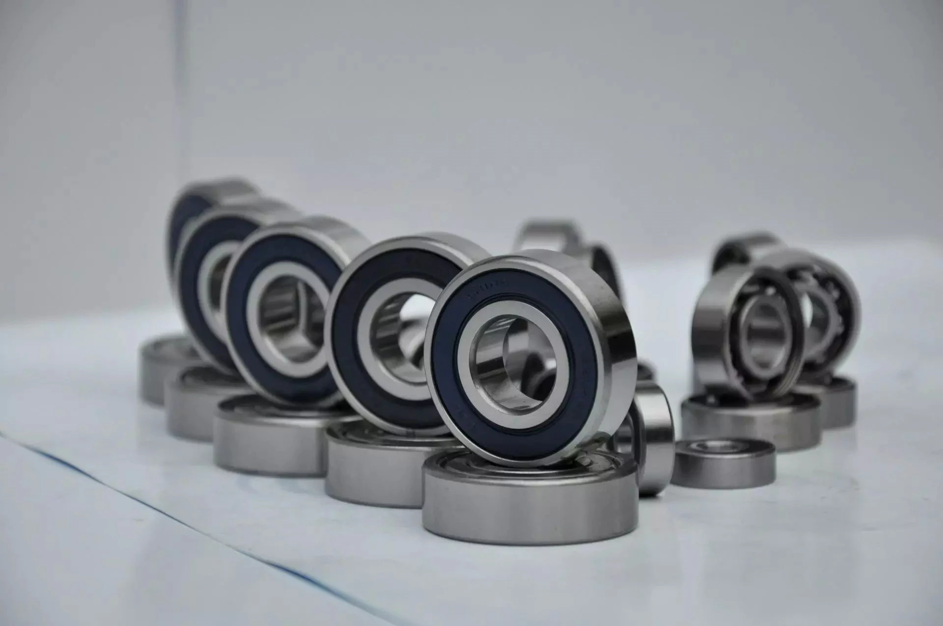
Types of Ball Bearings

In their most basic form, Ball Bearings have 1 common feature - they are made of steel. The majority of these bearings are made of 52100 steel, which has 1 percent chromium and 1 percent carbon. The steel can be hardened by heat trea
tment. 440C stainless steel is used for rusting problems. A cage around the ball balls is traditionally made from thin steel. However, some bearings use molded plastic cages to save money and friction.
bearing

Single-row designs

Steel linear translation stages often use single-row designs for ball bearings. These types of bearings provide smooth linear travel and can withstand high loads. The material steel has a high modulus of elasticity and a high stiffness, as well as a lower thermal expansion than aluminum. For these reasons, steel is the material of choice for a ball bearing in a typical user environment. Single-row designs for ball bearings are also suitable for applications in humid or corrosive environments.
Single-row designs for ball bearings are available in a variety of sizes and are axially adjustable. They have a high radial capacity, but require relatively little space. Single-row deep groove ball bearings with snap rings are STN 02 4605 or R47, respectively. Bearings with snap rings are identified by a suffix such as NR. They may not have seals or shields installed.
These single-row angular contact ball bearings are capable of supporting axial and radial loads. In a two-raceway arrangement, the radial load on bearing A causes a radial load to act on bearing B. Both axial and radial forces are transmitted between single-row angular contact ball bearings, and the resulting internal force must be taken into account to calculate equivalent dynamic bearing loads P.
Single-row deep groove ball bearings are the most common type of ball bearings. These bearings are designed with only 1 row of rolling elements. The single-row design is simple and durable, which makes it ideal for high-speed applications. Single-row designs for ball bearings are also available in various bore sizes. They can also come in a variety of shapes and are non-separable. If you need a high-speed bearing, you may want to opt for a double-row design.
In addition to single-row designs for ball bearings, you can choose ceramic or steel ball bearings. Ceramic balls are considerably harder than steel balls, but they are not as hard as steel. Hence, ceramic bearings are stiffer than steel ball bearings, resulting in increased stress on the outer race groove and lower load capacity. This is a great benefit for those who need the bearings to be lightweight and strong.
The difference between single-row and double-row designs is in the way that the inner and outer ring are installed. A single-row design places the inner ring in an eccentric position relative to the outer ring. The 2 rings are in contact at 1 point, which causes a large gap in the bearing. The balls are then inserted through the gap. As a result, the balls are evenly distributed throughout the bearing, which forces the inner and outer rings to become concentric.
Deep-groove ball bearings are 1 of the most popular types of ball bearings. They are available in different designs, including snap-ring, seal and shield arrangements. The race diameter of a deep-groove ball bearing is close to the ball's diameter. These types of bearings are suited for heavy loads, and their axial and radial support are excellent. Their main drawback is that the contact angle cannot be adjusted to accommodate a wide range of relative loads.
bearing

Ceramic hybrid ball bearings

Hybrid ball bearings with ceramic balls have numerous advantages. They feature improved kinematic behavior and require less lubrication. Consequently, they can reduce operating costs. Additionally, their low thermal expansion coefficient allows for smaller changes in contact angle and preload variations, and they can retain tolerances. Furthermore, ceramic hybrid ball bearings have significantly increased life spans compared to conventional steel-steel ball bearings, with up to 10 times the lifespan.
Although ceramic bearings can be used in automotive applications, many people believe that they're a poor choice for bicycle hubs. They don't reduce weight and only work well in high-rpm environments. As a result, many cyclists don't even bother with ceramic-based bearings. However, both Paul Lew and Alan are of the opinion that ceramic bearings are best suited for industrial or medical equipment applications. Furthermore, Paul and Alan believe that they are ideal for high-altitude drone motors.
Another advantage of ceramic hybrid ball bearings is that they use less friction than conventional steel-based balls. They are also more durable, requiring less lubrication than steel-based bearings. Furthermore, the lower friction and rolling resistance associated with ceramic-based ball bearings means that they can last 10 times longer than steel-based bearings. A ceramic-based hybrid ball bearing can be used for applications where speed and lubrication are critical.
Ceramic hybrid ball bearings feature both steel and silicon nitride balls. Silicon nitride balls have 50% more modulus of elasticity than steel balls and can improve accuracy and precision. Ceramic balls also have a smoother surface finish than steel balls, which reduces vibration and spindle deflection. These benefits result in increased speed and improved production quality. In addition to this, ceramic balls can also reduce the operating temperature, enhancing the work environment.
Hybrid bearings are a popular alternative to steel bearings. They have some benefits over traditional steel bearings, and are becoming a popular choice for engineered applications. Hybrid bearings are ideal for high speed machines. The material used to manufacture ceramic balls is a high-quality alloy, and is comparatively inexpensive. But you must understand that lubrication is still necessary for hybrid bearings. If you are not careful, you may end up wasting money.
These ball bearings can be used in many industries and applications, and they are widely compatible with most metals. The main advantage of hybrid ball bearings is that they are very durable. While steel balls tend to corrode and wear out, ceramic ball bearings can withstand these conditions while minimizing maintenance and replacement costs. The benefits of hybrid ball bearings are clear. So, consider switching to these newer types of ball bearings.
bearing

Self-aligning ball bearings

Self-aligning ball bearings are a good choice for many applications. They are a great alternative to traditional ball bearings, and they are ideal for rotating applications in which the shaft must move in several directions. They are also ideal for use in rotating parts where a tight tolerance is necessary. You can choose between 2 types: plain and flex shaft. Read on to find out which 1 will suit your needs.
Self-aligning ball bearings are designed with a higher axial load carrying capacity than single-row radial deep groove ball bearings. The amount of axial load carrying capacity is dependent upon the pressure angle. These bearings have a hollow raceway in the outer ring that allows the inner ring to pivot without friction. They are often used for high-speed applications. Because of their design, they are highly accurate.
Self-aligning ball bearings are radial bearings that feature 2 rows of balls in a spherical outer ring. They also feature 2 deep uninterrupted raceway grooves in the inner ring. Their unique features make them an excellent choice for applications where shaft deflection is a significant factor. Despite their small size, they have a high level of precision and can withstand heavy loads.
Self-aligning ball bearings can compensate for misalignment in shaft applications. The inner ring and ball assembly are positioned inside an outer ring containing a curved raceway. This spherical design allows the balls and cage to deflect and re-align around the bearing center. These bearings are also ideal for applications where shaft deflection is significant, such as in simple woodworking machinery.
Another type of self-aligning ball bearing uses a common concave outer race. Both balls and outer races automatically compensate for angular misalignment caused by machining, assembly, and deflections. Compared to spherical rollers, they have lower frictional losses than their spherical counterparts. Self-alignment ball bearings also have lower vibration levels compared to other types of bearings.
Self-aligning ball bearings operate in misaligned applications because their spherical outer raceway can accommodate misalignment. This design allows them to work in applications where shaft deflection or housing deformation is common. They are therefore more suitable for low to medium-sized loads. The only real drawback to self-aligning ball bearings is their price. If you need to purchase a self-aligning ball bearing for your next project, you can expect to pay around $1500.

China factory Factory Design Customized Engineering Hydraulic Cylinder     with high qualityChina factory Factory Design Customized Engineering Hydraulic Cylinder     with high quality