Tag Archives: china head cylinder

China Hot selling Hydraulic Hammer Front Head Cylinder with Hot selling

Product Description

Box Types of Hydraulic Breakers rock hammer for excavator breaker

High quality and competitive price
.Good after-sale service
.Contact with us to get more information
.Looking forward to cooperate with you


TYPE NAME  MODEL TYPE NAME MODEL TYPE NAME MODEL
 FURUKAWA HB100 GENERAL BREAKER GB1T SOOSAN  SH200
 FURUKAWA HB200 GENERAL BREAKER GB2T SOOSAN  SH400
 FURUKAWA HB700 GENERAL BREAKER GB3T SOOSAN  SH700
 FURUKAWA HB5G GENERAL BREAKER GB4T SOOSAN  SH-18G
 FURUKAWA HB8G GENERAL BREAKER GB5T SOOSAN  SH-20G
 FURUKAWA HB10G GENERAL BREAKER GB6T SOOSAN  SH-30G
 FURUKAWA HB15G GENERAL BREAKER GB8F SOOSAN  SH-35G
 FURUKAWA HB20G GENERAL BREAKER GB8T SOOSAN  SH-40G
 FURUKAWA HB30G GENERAL BREAKER GB11T SOOSAN  SB-30
 FURUKAWA HB40G GENERAL BREAKER GB14T SOOSAN  SB-35
 FURUKAWA HB50G GENERAL BREAKER GB8AT SOOSAN  SB-40
 FURUKAWA HB1200 GENERAL BREAKER GB170E SOOSAN  SB-43
 FURUKAWA F5 GENERAL BREAKER GB220E SOOSAN  SB-45
 FURUKAWA F6 GENERAL BREAKER GB290E SOOSAN  SB-50
 FURUKAWA F9 GENERAL BREAKER GB300E SOOSAN  SB-60
 FURUKAWA F12 GENERAL BREAKER GB320E SOOSAN  SB-70
 FURUKAWA F19 GENERAL BREAKER GB400E SOOSAN  SB-81
 FURUKAWA F22 GENERAL BREAKER GB526E SOOSAN  SB-100
 FURUKAWA F27     SOOSAN  SB-121
 FURUKAWA F35     SOOSAN  SB-131
 FURUKAWA F45     SOOSAN  SB-151
 FURUKAWA F70        

Product process:

Forging- - Turnery- - Heat treatment- - Painting- - Inspection

*Our promise:

=== Small order is acceptable

=== OEM is acceptable

=== Any third party testing is acceptable

=== 12Months quality guarantee

24 hours service for you! We are waiting for you!
*Specification of chisel:
*1. Full size & large supply;
* 2. Factory supplier
*3. Applications:
A. Cone---universal tool
B. Wedged---demolition work, road construction, bridge foundation
C. Blunt---mining, quarring, crushing rock
D. Moil point---demolition work, road construction, bridge foundation
* 4. Surface: Smooth
* 5. Delivery time: Within10days after receipt of deposit asap.;
* 6. Packing: Standard exporting package & as customers' need.


*Our advantage:

* 1. Price------Competitive price=We produce, which greatly reduce our cost!

*2. Product---Special alloy steel+ special smithing technics+ special heat
Treatment method+ superior performance and price ratio

*3. Expertise--We have a technician team and a QC team, which ensure
Our products is exactly what you want.

* 4. Productivity------We have large-scale production line, which guarantee
All your orders will be finished in earlist time

*5. Materials----------All chisels are made of high-quality raw materials.

* 6. Service-------------We are on standby for your best service
If you need other reletive information please check our website and contact me directly.

FAQ

Q: Are you trading company or manufacturer ?
A: We are factory.

Q: How long is your delivery time?
A: Generally it is 5-10 days if the goods are in stock. or it is 15-20 days if the goods are not in stock, it is according to quantity.

Q: Do you provide samples ? is it free or extra ?
A: Yes, we could offer the sample for free charge but do not pay the cost of freight.

Q: What is your terms of payment ?
A: Payment=1000USD, 30% T/T in advance ,balance before shippment.

If you have other requirements,please feel free to contact with Irene Mei.


Send your inquiry details in the below, and click "send" Now ! ↓↓↓↓↓↓
 

How to Determine the Quality of a Worm Shaft

There are many advantages of a worm shaft. It is easier to manufacture, as it does not require manual straightening. Among these benefits are ease of maintenance, reduced cost, and ease of installation. In addition, this type of shaft is much less prone to damage due to manual straightening. This article will discuss the different factors that determine the quality of a worm shaft. It also discusses the Dedendum, Root diameter, and Wear load capacity.
worm shaft

Root diameter

There are various options when choosing worm gearing. The selection depends on the transmission used and production possibilities. The basic profile parameters of worm gearing are described in the professional and firm literature and are used in geometry calculations. The selected variant is then transferred to the main calculation. However, you must take into account the strength parameters and the gear ratios for the calculation to be accurate. Here are some tips to choose the right worm gearing.
The root diameter of a worm gear is measured from the center of its pitch. Its pitch diameter is a standardized value that is determined from its pressure angle at the point of zero gearing correction. The worm gear pitch diameter is calculated by adding the worm's dimension to the nominal center distance. When defining the worm gear pitch, you have to keep in mind that the root diameter of the worm shaft must be smaller than the pitch diameter.
Worm gearing requires teeth to evenly distribute the wear. For this, the tooth side of the worm must be convex in the normal and centre-line sections. The shape of the teeth, referred to as the evolvent profile, resembles a helical gear. Usually, the root diameter of a worm gear is more than a quarter inch. However, a half-inch difference is acceptable.
Another way to calculate the gearing efficiency of a worm shaft is by looking at the worm's sacrificial wheel. A sacrificial wheel is softer than the worm, so most wear and tear will occur on the wheel. Oil analysis reports of worm gearing units almost always show a high copper and iron ratio, suggesting that the worm's gearing is ineffective.

Dedendum

The dedendum of a worm shaft refers to the radial length of its tooth. The pitch diameter and the minor diameter determine the dedendum. In an imperial system, the pitch diameter is referred to as the diametral pitch. Other parameters include the face width and fillet radius. Face width describes the width of the gear wheel without hub projections. Fillet radius measures the radius on the tip of the cutter and forms a trochoidal curve.
The diameter of a hub is measured at its outer diameter, and its projection is the distance the hub extends beyond the gear face. There are 2 types of addendum teeth, 1 with short-addendum teeth and the other with long-addendum teeth. The gears themselves have a keyway (a groove machined into the shaft and bore). A key is fitted into the keyway, which fits into the shaft.
Worm gears transmit motion from 2 shafts that are not parallel, and have a line-toothed design. The pitch circle has 2 or more arcs, and the worm and sprocket are supported by anti-friction roller bearings. Worm gears have high friction and wear on the tooth teeth and restraining surfaces. If you'd like to know more about worm gears, take a look at the definitions below.
worm shaft

CZPT's whirling process

Whirling process is a modern manufacturing method that is replacing thread milling and hobbing processes. It has been able to reduce manufacturing costs and lead times while producing precision gear worms. In addition, it has reduced the need for thread grinding and surface roughness. It also reduces thread rolling. Here's more on how CZPT whirling process works.
The whirling process on the worm shaft can be used for producing a variety of screw types and worms. They can produce screw shafts with outer diameters of up to 2.5 inches. Unlike other whirling processes, the worm shaft is sacrificial, and the process does not require machining. A vortex tube is used to deliver chilled compressed air to the cutting point. If needed, oil is also added to the mix.
Another method for hardening a worm shaft is called induction hardening. The process is a high-frequency electrical process that induces eddy currents in metallic objects. The higher the frequency, the more surface heat it generates. With induction heating, you can program the heating process to harden only specific areas of the worm shaft. The length of the worm shaft is usually shortened.
Worm gears offer numerous advantages over standard gear sets. If used correctly, they are reliable and highly efficient. By following proper setup guidelines and lubrication guidelines, worm gears can deliver the same reliable service as any other type of gear set. The article by Ray Thibault, a mechanical engineer at the University of Virginia, is an excellent guide to lubrication on worm gears.

Wear load capacity

The wear load capacity of a worm shaft is a key parameter when determining the efficiency of a gearbox. Worms can be made with different gear ratios, and the design of the worm shaft should reflect this. To determine the wear load capacity of a worm, you can check its geometry. Worms are usually made with teeth ranging from 1 to 4 and up to twelve. Choosing the right number of teeth depends on several factors, including the optimisation requirements, such as efficiency, weight, and centre-line distance.
Worm gear tooth forces increase with increased power density, causing the worm shaft to deflect more. This reduces its wear load capacity, lowers efficiency, and increases NVH behavior. Advances in lubricants and bronze materials, combined with better manufacturing quality, have enabled the continuous increase in power density. Those 3 factors combined will determine the wear load capacity of your worm gear. It is critical to consider all 3 factors before choosing the right gear tooth profile.
The minimum number of gear teeth in a gear depends on the pressure angle at zero gearing correction. The worm diameter d1 is arbitrary and depends on a known module value, mx or mn. Worms and gears with different ratios can be interchanged. An involute helicoid ensures proper contact and shape, and provides higher accuracy and life. The involute helicoid worm is also a key component of a gear.
Worm gears are a form of ancient gear. A cylindrical worm engages with a toothed wheel to reduce rotational speed. Worm gears are also used as prime movers. If you're looking for a gearbox, it may be a good option. If you're considering a worm gear, be sure to check its load capacity and lubrication requirements.
worm shaft

NVH behavior

The NVH behavior of a worm shaft is determined using the finite element method. The simulation parameters are defined using the finite element method and experimental worm shafts are compared to the simulation results. The results show that a large deviation exists between the simulated and experimental values. In addition, the bending stiffness of the worm shaft is highly dependent on the geometry of the worm gear toothings. Hence, an adequate design for a worm gear toothing can help reduce the NVH (noise-vibration) behavior of the worm shaft.
To calculate the worm shaft's NVH behavior, the main axes of moment of inertia are the diameter of the worm and the number of threads. This will influence the angle between the worm teeth and the effective distance of each tooth. The distance between the main axes of the worm shaft and the worm gear is the analytical equivalent bending diameter. The diameter of the worm gear is referred to as its effective diameter.
The increased power density of a worm gear results in increased forces acting on the corresponding worm gear tooth. This leads to a corresponding increase in deflection of the worm gear, which negatively affects its efficiency and wear load capacity. In addition, the increasing power density requires improved manufacturing quality. The continuous advancement in bronze materials and lubricants has also facilitated the continued increase in power density.
The toothing of the worm gears determines the worm shaft deflection. The bending stiffness of the worm gear toothing is also calculated by using a tooth-dependent bending stiffness. The deflection is then converted into a stiffness value by using the stiffness of the individual sections of the worm shaft. As shown in figure 5, a transverse section of a two-threaded worm is shown in the figure.

China Hot selling Hydraulic Hammer Front Head Cylinder     with Hot sellingChina Hot selling Hydraulic Hammer Front Head Cylinder     with Hot selling

China OEM Back Head Main Body Sb40 Sb43 Sb45 Sb50 Hydraulic Breaker Parts Front Head Cylinder with Great quality

Product Description

Product Description

 We are manufacturer of hydraulic breakers/hammers and replacement spare parts for hydraulic breakers of, Hanwoo,NPK montabert, rammer, atlas copco, MSB etc., The hydraulic breaker parts we have are: front head, back head, cylinder, chisel tool, seal kits ,piston, diaphragm, thrust bush, ring bush, front cover ,rod pin/chisel pin, stop pin, accumulator, through bolt, side bolt , bracket, upper cushion, lower cushion ,damper etc.
We can also make and install excavator hydraulic kits/hammer lines/piping kits/hydraulic installation kits/breaker lines for hydraulic hammer, hydraulic shear, hydraulic crusher, quick coupler, demolition grab, power rammer etc. We can also supply other excavator parts.


Production and Processing


Company Information

HangZhou Changhao Mechanical Equipment Co., Ltd.

Our company mainly produces hydraulic breaker parts and breaker pipeline parts.  We can supply different kinds of hydraulic breaker spare parts, such as chisel, oil seal, through bolt, side bolt, nitrogen bottle, cover & bush, tool box, oil tube, filter, piston, piston ring, front head, back head, cylinder, flat pin, round pin, etc. 

 The hydraulic breaker/hammer spare parts we supply are front head, cylinder,back head, chisel, piston,seal kits,diaphragm,front cover, thrush bush,ring bush,charging valve,accumulator,through bolt,side bolt, bracket, N2 charging device etc.
Excavator hammer lines/piping kits/auxiliary installation pipelines for attachment are available too.

All the accessories of our pipeline, including clamps, ball valves, Overflow valve, foot valve, iron pipe, hose, etc. All of our pipelines are acid-washed and phosphated to ensure that the inside of the pipeline is clean and dust-free, and the hydraulic system of the excavator is clean and pollution-free. Our company's product pipelines are welded by domestic first-class welders. After welding, the joints are formed by single-sided welding and double-sided welding to ensure that the product will never leak oil. 

Our products have been exporting to many countries in the world with advanced machines and strict quality control management, the advanced production equipment and impeccable QC system help us make sure the highest-quality and cost-effective products.Our products have reached the international advanced level. Cooperating with large number of well-known dealers in the domestic and foreign market. We have our own production plant, covering an area of about 3000 square meters. Our workers are skilled in craftsmanship and rich in experience, coupled with the blessing of advanced machinery and equipment, the quality of the products delivered is safe and reliable.Our products are of high quality, reasonable prices and efficient delivery. 

High quality,competitive price and innovative products can be promised and stock samples can be available for your evaluation. 
Welcome to visit our factory and contact us!

Main Products


     Pipeline section view

Our pipeline series are complete, including all series from Carter,  Hitachi, Volvo, Kobelco,  Xugong, Liugong. All of our pipelines are acid-washed and phosphated to ensure that the inside of the pipeline is clean and dust-free, and the hydraulic system of the excavator is clean and pollution-free.
The outer surface of the pipeline is sprayed with plastic paint, and the colors are various, which are exactly the same as the color of the excavator body. Meet all your requirement for color.
All the accessories of our pipeline, including clamps, ball valves, overflow valve, foot valve, iron pipe, hose,etc, are independently developed and manufactured by our factory to ensure product quality, safety and reliability.

Our company's product pipelines are welded by domestic first-class welders. After welding, the joints are formed by single-sided welding and double-sided welding to ensure that the product will never leak oil.

Packing and Shipping

Payment:
We usually use TT.
TT 30% deposit  before production and balance 70% before delivery or against B/L copy if see shipment.
100% L/C at sight if you purchase in large quantities. 

Shipping: 
If the quantity of order is not very big, we could send them to you by express delivery, such as TNT, DHL, UPS or EMS etc.
If the order is large, we usually ship from HangZhou Port, China.

Our company wants to establish a long-term friendly business relationship with your respected company. If you are interested in our products, please contact us directly. We look forward to your inquiry. 

Contact person: Xinzhao                           

Worm Shafts and Gearboxes

If you have a gearbox, you may be wondering what the best Worm Shaft is for your application. There are several things to consider, including the Concave shape, Number of threads, and Lubrication. This article will explain each factor and help you choose the right Worm Shaft for your gearbox. There are many options available on the market, so don't hesitate to shop around. If you are new to the world of gearboxes, read on to learn more about this popular type of gearbox.
worm shaft

Concave shape

The geometry of a worm gear varies considerably depending on its manufacturer and its intended use. Early worms had a basic profile that resembled a screw thread and could be chased on a lathe. Later, tools with a straight sided g-angle were developed to produce threads that were parallel to the worm's axis. Grinding was also developed to improve the finish of worm threads and minimize distortions that occur with hardening.
To select a worm with the proper geometry, the diameter of the worm gear must be in the same unit as the worm's shaft. Once the basic profile of the worm gear is determined, the worm gear teeth can be specified. The calculation also involves an angle for the worm shaft to prevent it from overheating. The angle of the worm shaft should be as close to the vertical axis as possible.
Double-enveloping worm gears, on the other hand, do not have a throat around the worm. They are helical gears with a straight worm shaft. Since the teeth of the worm are in contact with each other, they produce significant friction. Unlike double-enveloping worm gears, non-throated worm gears are more compact and can handle smaller loads. They are also easy to manufacture.
The worm gears of different manufacturers offer many advantages. For instance, worm gears are 1 of the most efficient ways to increase torque, while lower-quality materials like bronze are difficult to lubricate. Worm gears also have a low failure rate because they allow for considerable leeway in the design process. Despite the differences between the 2 standards, the overall performance of a worm gear system is the same.
The cone-shaped worm is another type. This is a technological scheme that combines a straight worm shaft with a concave arc. The concave arc is also a useful utility model. Worms with this shape have more than 3 contacts at the same time, which means they can reduce a large diameter without excessive wear. It is also a relatively low-cost model.
worm shaft

Thread pattern

A good worm gear requires a perfect thread pattern. There are a few key parameters that determine how good a thread pattern is. Firstly, the threading pattern must be ACME-threaded. If this is not possible, the thread must be made with straight sides. Then, the linear pitch of the "worm" must be the same as the circular pitch of the corresponding worm wheel. In simple terms, this means the pitch of the "worm" is the same as the circular pitch of the worm wheel. A quick-change gearbox is usually used with this type of worm gear. Alternatively, lead-screw change gears are used instead of a quick-change gear box. The pitch of a worm gear equals the helix angle of a screw.
A worm gear's axial pitch must match the circular pitch of a gear with a higher axial pitch. The circular pitch is the distance between the points of teeth on the worm, while the axial pitch is the distance between the worm's teeth. Another factor is the worm's lead angle. The angle between the pitch cylinder and worm shaft is called its lead angle, and the higher the lead angle, the greater the efficiency of a gear.
Worm gear tooth geometry varies depending on the manufacturer and intended use. In early worms, threading resembled the thread on a screw, and was easily chased using a lathe. Later, grinding improved worm thread finishes and minimized distortions from hardening. As a result, today, most worm gears have a thread pattern corresponding to their size. When selecting a worm gear, make sure to check for the number of threads before purchasing it.
A worm gear's threading is crucial in its operation. Worm teeth are typically cylindrical, and are arranged in a pattern similar to screw or nut threads. Worm teeth are often formed on an axis of perpendicular compared to their parallel counterparts. Because of this, they have greater torque than their spur gear counterparts. Moreover, the gearing has a low output speed and high torque.

Number of threads

Different types of worm gears use different numbers of threads on their planetary gears. A single threaded worm gear should not be used with a double-threaded worm. A single-threaded worm gear should be used with a single-threaded worm. Single-threaded worms are more effective for speed reduction than double-threaded ones.
The number of threads on a worm's shaft is a ratio that compares the pitch diameter and number of teeth. In general, worms have 1,2,4 threads, but some have three, five, or six. Counting thread starts can help you determine the number of threads on a worm. A single-threaded worm has fewer threads than a multiple-threaded worm, but a multi-threaded worm will have more threads than a mono-threaded planetary gear.
To measure the number of threads on a worm shaft, a small fixture with 2 ground faces is used. The worm must be removed from its housing so that the finished thread area can be inspected. After identifying the number of threads, simple measurements of the worm's outside diameter and thread depth are taken. Once the worm has been accounted for, a cast of the tooth space is made using epoxy material. The casting is moulded between the 2 tooth flanks. The V-block fixture rests against the outside diameter of the worm.
The circular pitch of a worm and its axial pitch must match the circular pitch of a larger gear. The axial pitch of a worm is the distance between the points of the teeth on a worm's pitch diameter. The lead of a thread is the distance a thread travels in 1 revolution. The lead angle is the tangent to the helix of a thread on a cylinder.
The worm gear's speed transmission ratio is based on the number of threads. A worm gear with a high ratio can be easily reduced in 1 step by using a set of worm gears. However, a multi-thread worm will have more than 2 threads. The worm gear is also more efficient than single-threaded gears. And a worm gear with a high ratio will allow the motor to be used in a variety of applications.
worm shaft

Lubrication

The lubrication of a worm gear is particularly challenging, due to its friction and high sliding contact force. Fortunately, there are several options for lubricants, such as compounded oils. Compounded oils are mineral-based lubricants formulated with 10 percent or more fatty acid, rust and oxidation inhibitors, and other additives. This combination results in improved lubricity, reduced friction, and lower sliding wear.
When choosing a lubricant for a worm shaft, make sure the product's viscosity is right for the type of gearing used. A low viscosity will make the gearbox difficult to actuate and rotate. Worm gears also undergo a greater sliding motion than rolling motion, so grease must be able to migrate evenly throughout the gearbox. Repeated sliding motions will push the grease away from the contact zone.
Another consideration is the backlash of the gears. Worm gears have high gear ratios, sometimes 300:1. This is important for power applications, but is at the same time inefficient. Worm gears can generate heat during the sliding motion, so a high-quality lubricant is essential. This type of lubricant will reduce heat and ensure optimal performance. The following tips will help you choose the right lubricant for your worm gear.
In low-speed applications, a grease lubricant may be sufficient. In higher-speed applications, it's best to apply a synthetic lubricant to prevent premature failure and tooth wear. In both cases, lubricant choice depends on the tangential and rotational speed. It is important to follow manufacturer's guidelines regarding the choice of lubricant. But remember that lubricant choice is not an easy task.

China OEM Back Head Main Body Sb40 Sb43 Sb45 Sb50 Hydraulic Breaker Parts Front Head Cylinder     with Great qualityChina OEM Back Head Main Body Sb40 Sb43 Sb45 Sb50 Hydraulic Breaker Parts Front Head Cylinder     with Great quality

China Hot selling Hydraulic Breaker Spare Parts Front Head Back Head and Cylinder with high quality

Product Description

****OUR FACTORY

***we are a factory in HangZhou city,ZheJiang province,China

specialized in manufacturing hydraulic breaker ,quick hitch ,ripper ,etc for excavator attachment .

OUR FACTORY IN HangZhou CITY,ZheJiang PROVINCE ,CHINA
OUR PRODUCT SPECAILIZED IN MANUFACTURE HYDRAULIC HAMMER
MOQ 1 SET
OEM YES.BECAUSE WE ARE A FACTORY
COLOR ANY COLOR COULD DO FOR YOU
PAYMENT 30% DEPOSIT ,BALANCE BEFORE SHIPPING ,T/T OR L/C
DELIVERY DATE 1-50 SET 1-25DAYS.
SHIPPING BY SEA O BY AIR


* HangZhou Factory Direct Price
* Small order is welcome, MOQ 1 set
* Nice quality, 1 year warranty
* Chisel diameter from 35-210mm
* Breaker suit any brand 0.5-70 ton excavator
* Fit to machine as below:

YTCT HYDRAULIC BREAKER HAMMER:

MODE NUMBER CHISEL DIAMETER SUIT EXCAVATOR (WEIGHT) BRAND OF EXCAVATOR HYDRAULIC OIL FLOW HYDRAULIC PRESSURE BLOW FREQUENCY MAIN BODY WEIGHT HOSE DIAMETER ACCUMALATOR PRESSURE
YTCT MM TON   L/MIN KG/CM2 BMP KG INCH KG/CM2
YTCT 35 0.5-0.8 ANY BRAND 10--20 90-120 800-1400 40 1/2 /
YTCT10 40 0.8-2.5 15-25 90-120 800-1400 53 1/2 /
YTCT20 45 1.2-3.0 20-30 90-120 700-1200 71 1/2 /
YTCT30 53 2.5-4.5 25-50 90-120 600-1100 89 1/2 /
YTCT40 68 4--7 40-70 110-140 500-900 156 1/2 /
YTCT43 75 6--9 50-90 120-150 400-800 214 1/2 /
YTCT45 85 7--14 60-100 130-160 400-800 282 1/2 /
YTCT50 100 10--15 80-110 150-170 350-700 479 3/4 /
YTCT70 135 16-25 130-150 160-180 400-800 850 1 /
YTCT81 140 18-26 120-180 160-180 350-500 920 1 /
YTCT81A 140 18-26 120-180 160-180 350-500 956 1 60
YTCT100 150 27-35 150-190 160-180 350-700 2218 1 60
YTCT121 155 28-35 180-240 160-180 300-450 2577 1 60
YTCT131 165 30-40 200-260 160-180 250-400 1442 1 60
YTCT140 165 30-40 200-270 160-180 250-380 1590 1 60
YTCT151 175 35-40 210-290 160-180 200-350 1925 5/4 60
YTCT151L 175 35-45 220-270 200-240 200-300 1933 5/4 60
YTCT185 185 40-55 220-270 180-220 250-320 2295 5/4 60
YTCT190 190 45-60 220-290 180-220 180-200 2526 5/4 60
YTCT195 195 45-60 220-290 180-220 180-200 2600 5/4 60

ALL THE PRICE WITH SPARE PARTS AS BELOW:

1.all the price with wooden box pacakage .
2.all the price with the standard spare parts.
** -----2 chisels
** -----2 oil tube
** -----1 N2 gas bottle.
** -----1 tool box
** -----1 N2 pressure gauge

PACKING AND SHIPPING

1.Inner is stretch film, outside is export plywood case or as customer's request

2.Delivery time:Usually 3-7days (1-5sets) after down payment.

3..We can arrange CZPT or air transportation according to your request from any port of China.

HOW TO CHOOSE OUR BREAKER ?

1. PLEASE LET US KNOW YOUR EXCAVATOR MODEL NUMBER OR WEIGHT OF MACHINE.

2.PLEASE LET US KNOW WHAT COLOR DO YOU NEED FOR BREAKER .

3.PLEASE CHECK THE ABCDE SIZE FOR US ,ARM EAR WIDTH ,PIN DIAMETER AND PIN CENTER TO PIN CENTER SIZE .

4.CHOOSE WHAT TYPE OF HYDRAULIC BREAKRE DO YOU NEED ,THANKS.

NEED FREE CATALOG OR MORE PRICE,SEND ME INQUIRY AS BELOW.

MISS EVA WILL REPLY SOON,THANKS.


How Metal Fabrication Benefits Agricultural Parts

agricultural parts

If you own an agricultural farm, you probably have a variety of different kinds of agricultural parts. These include tractors, hand tools, and other types of farm implements. Here, you'll learn how to identify different parts and the importance of knowing what they do. Then, you can order them online to have them shipped directly to you. You can also contact different agricultural equipment dealers to find out where to buy agricultural parts. Regardless of where you get them, they'll be worth the investment.
agriculturalparts

Metal fabricated agricultural parts

Regardless of the industry, metal fabricated agricultural parts can benefit a farm. For starters, metal fabricated parts are easier to replace than alternatives. Because metal is stronger than plastic, these parts can be made lighter. This means faster equipment movement and increased productivity. Metal can also be easily customized, allowing for a custom-made product. The benefits of metal fabrication extend far beyond the agricultural industry. Listed below are several of the benefits of using metal fabricated parts.
Agricultural equipment is exposed to harsh weather conditions. This is why it is imperative that metal fabricated agricultural parts are made with durable materials. Additionally, metal fabricated parts have a lower chance of corroding, which helps keep equipment running more efficiently. With such a long list of benefits, it's easy to see why metal fabricated parts are so popular with farmers. And if your company needs agricultural equipment parts that can withstand the elements, you can depend on Hynes Industries.
Agricultural equipment requires metal parts that can withstand the rigorous workloads. As a trusted vendor, Evan's Manufacturing provides comprehensive metal fabrication services for agricultural equipment. With our advanced laser cutting services, you can rest assured that your metal parts are in good hands. You'll be able to make adjustments without affecting the integrity of the metal. And thanks to our streamlined process, the quality of your fabricated parts is unrivaled.
Whether you need a custom fitout for a new piece of farm equipment, or a new design for an existing piece, metal fabrication can help. Custom fitouts not only improve the comfort of the operator, but also increase the durability of your farm machinery. Almost every type of metal fabrication process is used in the agricultural industry. These include brazing, welding, soldering, drilling, milling, and laser engraving.
As the manufacturing process of agricultural machinery becomes increasingly automated, sheet metal fabrication has become an important part of the production process. This process allows for more precise and accurate processing of holes of various shapes and sizes, and the cost of production is lowered significantly. Additionally, because of its precision and stability, sheet metal fabrication is perfect for farming. Moreover, it's easy to teach and maintain automated processes. With these machines, farmers can make small batches easily, improving the efficiency of agricultural production.
agriculturalparts

Agricultural machinery manufacturers

Agricultural machinery is a highly technological industry with a large market for OEM parts. The demand for agricultural equipment is expected to reach $118.2 billion by 2025, which is higher than the previous forecast. Today, modern tech developments have increased the productivity and profitability of farms, making it more profitable to use farm equipment. Moreover, the availability of OEM parts is a key driving factor for the market growth. The agricultural equipment market will see continued growth as manufacturers focus on safety, quality, and consistent improvement of their products.
AGCO Corporation is an agricultural machinery manufacturer based in Duluth, Georgia. It was formed through a merger with Allis-Chalmers in 1990. The company's growth has been achieved through numerous acquisitions in farm machinery. It first acquired the Hesston forage and hay line from Fiat, which included a 50% share in a manufacturing joint venture with Case IH. Moreover, it acquired the White tractor business from Allied Products to expand its dealer network.
Among the major factors contributing to the supply chain breakdown for farm equipment manufacturers is the outbreak of COVID-19. The pandemic has affected the supply chain in several ways, including reducing the availability of raw materials and component parts. It also has affected the labor force by causing temporary layoffs and illness. Furthermore, the shortage of steel is causing manufacturers to struggle to meet demand. As a result, the company has to delay shipments to meet customer demand.
In addition to the above factors, the rising cost of labor is another factor driving equipment sales. Using auto-guidance systems to match the yield of a crop is an effective way to maximize yield while minimizing environmental impact. Another major factor driving agricultural equipment sales is the increasing cost of agricultural labor across regions. This pay differential between industrial workers and those in the agricultural sector is 1 of the most common secular drivers for demand for agricultural equipment.
A large proportion of agricultural equipment is oversized for economic reasons. For instance, a combine can do 3 different processes at once. It can also travel across several states or even countries. The need for reliable transportation companies is another critical factor in the industry. The majority of companies in this industry are family-owned and operated. A good transportation network is essential to keep equipment on the road. This is a major challenge for the industry.
The European Union accounts for a large proportion of agricultural machinery manufacturing, with total output of 28 billion euros (2014). The top 3 countries for production are Germany, Italy, and France, with each country accounting for around 17 per cent of the global total. The majority of leading international manufacturers maintain several production sites across the continent. The products produced at these facilities are typically for high-end customers. They can also be purchased from a variety of independent sources.
agriculturalparts

Agricultural equipment dealers

Agricultural equipment dealerships are facing a changing landscape. Today's consumers expect businesses to be online 24/7, have faster response times, and allow them to make payments more conveniently. To keep up with these expectations, more dealers are making the switch to mobile apps. These apps simplify all areas of business, from sales to service, and allow technicians to receive work orders directly on their mobile devices. In addition, the growth of ag equipment manufacturers is fueling the trend of consolidation among ag equipment dealers.
Video marketing is especially useful for agricultural equipment dealers. Agricultural equipment dealers can utilize video marketing from firms such as Kirkpatrick Creative. Unlike text, video allows marketers to connect emotionally with their customers, by showing them a face. It is much more difficult to establish this connection through text, so video is a great way to reach potential customers. If a customer is satisfied with the process, they are more likely to buy from them again.
To succeed in sales of agricultural equipment, candidates should possess a combination of equipment knowledge, communication skills, and tenacity. Sales compensation packages for this industry are heavily based on commissions, so new salespeople should be prepared to work without a guaranteed monthly check. Agricultural equipment dealers should be ready for this kind of change in the coming years and prepare their sales funnels to make the transition. In addition, they should make sure that their phone numbers are prominently displayed.
The laws governing agricultural equipment dealers vary from state to state. These laws protect farm equipment dealers by outlining their rights as a supplier and a manufacturer. While these laws may have some commonalities, they do have some differences, which makes them essential to fully understand. Several procedures which are legal in 1 state may not be allowed in another. For this reason, it is vital that the dealer understand the laws of his state and be familiar with the relevant legislation.
The shortage of labor in the agriculture sector is a major challenge for many growers. But the shortage of labor could spur sales of robotics and automation equipment that simplify the farming process. With the right tools, a farm can run more efficiently and reduce its worker headcount. Therefore, the lack of labor will continue to be a major problem for agricultural equipment dealers. With this in mind, it is imperative to choose the right dealer for the job.
The influx of new equipment has made it difficult for agricultural equipment manufacturers to meet demand. Many companies have struggled to get implements to dealerships on time, making the overall situation even more complicated. Agricultural equipment dealers have to wait weeks or even months for their new machines to be delivered to farmers. A tractor from John Deere, for instance, can take 5 or 6 weeks to arrive in a dealership. It can now take 18 to 22 weeks, depending on the size of the order.

China Hot selling Hydraulic Breaker Spare Parts Front Head Back Head and Cylinder     with high qualityChina Hot selling Hydraulic Breaker Spare Parts Front Head Back Head and Cylinder     with high quality

China supplier Hydraulic Breaker Front Head Back Head Hb20g Hb30g Hb40g Cylinder near me factory

Product Description

****OUR FACTORY

***we are a factory in HangZhou city,ZheJiang province,China

specialized in manufacturing hydraulic breaker ,quick hitch ,ripper ,etc for excavator attachment .

OUR FACTORY IN HangZhou CITY,ZheJiang PROVINCE ,CHINA
OUR PRODUCT SPECAILIZED IN MANUFACTURE HYDRAULIC HAMMER
MOQ 1 SET
OEM YES.BECAUSE WE ARE A FACTORY
COLOR ANY COLOR COULD DO FOR YOU
PAYMENT 30% DEPOSIT ,BALANCE BEFORE SHIPPING ,T/T OR L/C
DELIVERY DATE 1-50 SET 1-25DAYS.
SHIPPING BY SEA O BY AIR


* HangZhou Factory Direct Price
* Small order is welcome, MOQ 1 set
* Nice quality, 1 year warranty
* Chisel diameter from 35-210mm
* Breaker suit any brand 0.5-70 ton excavator
* Fit to machine as below:

YTCT HYDRAULIC BREAKER HAMMER:

MODE NUMBER CHISEL DIAMETER SUIT EXCAVATOR (WEIGHT) BRAND OF EXCAVATOR HYDRAULIC OIL FLOW HYDRAULIC PRESSURE BLOW FREQUENCY MAIN BODY WEIGHT HOSE DIAMETER ACCUMALATOR PRESSURE
YTCT MM TON   L/MIN KG/CM2 BMP KG INCH KG/CM2
YTCT 35 0.5-0.8 ANY BRAND 10--20 90-120 800-1400 40 1/2 /
YTCT10 40 0.8-2.5 15-25 90-120 800-1400 53 1/2 /
YTCT20 45 1.2-3.0 20-30 90-120 700-1200 71 1/2 /
YTCT30 53 2.5-4.5 25-50 90-120 600-1100 89 1/2 /
YTCT40 68 4--7 40-70 110-140 500-900 156 1/2 /
YTCT43 75 6--9 50-90 120-150 400-800 214 1/2 /
YTCT45 85 7--14 60-100 130-160 400-800 282 1/2 /
YTCT50 100 10--15 80-110 150-170 350-700 479 3/4 /
YTCT70 135 16-25 130-150 160-180 400-800 850 1 /
YTCT81 140 18-26 120-180 160-180 350-500 920 1 /
YTCT81A 140 18-26 120-180 160-180 350-500 956 1 60
YTCT100 150 27-35 150-190 160-180 350-700 2218 1 60
YTCT121 155 28-35 180-240 160-180 300-450 2577 1 60
YTCT131 165 30-40 200-260 160-180 250-400 1442 1 60
YTCT140 165 30-40 200-270 160-180 250-380 1590 1 60
YTCT151 175 35-40 210-290 160-180 200-350 1925 5/4 60
YTCT151L 175 35-45 220-270 200-240 200-300 1933 5/4 60
YTCT185 185 40-55 220-270 180-220 250-320 2295 5/4 60
YTCT190 190 45-60 220-290 180-220 180-200 2526 5/4 60
YTCT195 195 45-60 220-290 180-220 180-200 2600 5/4 60

ALL THE PRICE WITH SPARE PARTS AS BELOW:

1.all the price with wooden box pacakage .
2.all the price with the standard spare parts.
** -----2 chisels
** -----2 oil tube
** -----1 N2 gas bottle.
** -----1 tool box
** -----1 N2 pressure gauge

PACKING AND SHIPPING

1.Inner is stretch film, outside is export plywood case or as customer's request

2.Delivery time:Usually 3-7days (1-5sets) after down payment.

3..We can arrange CZPT or air transportation according to your request from any port of China.

HOW TO CHOOSE OUR BREAKER ?

1. PLEASE LET US KNOW YOUR EXCAVATOR MODEL NUMBER OR WEIGHT OF MACHINE.

2.PLEASE LET US KNOW WHAT COLOR DO YOU NEED FOR BREAKER .

3.PLEASE CHECK THE ABCDE SIZE FOR US ,ARM EAR WIDTH ,PIN DIAMETER AND PIN CENTER TO PIN CENTER SIZE .

4.CHOOSE WHAT TYPE OF HYDRAULIC BREAKRE DO YOU NEED ,THANKS.

NEED FREE CATALOG OR MORE PRICE,SEND ME INQUIRY AS BELOW.

MISS EVA WILL REPLY SOON,THANKS.


What You Should Know About Axle Shafts

There are several things you should know about axle shafts. These include what materials they're made of, how they're constructed, and the signs of wear and tear. Read on to learn more about axle shafts and how to properly maintain them. Axle shafts are a crucial part of any vehicle. But how can you tell if 1 is worn out? Here are some tips that can help you determine whether it's time to replace it.

Materials used for axle shafts

When it comes to materials used in axle shafts, there are 2 common types of materials. One is carbon fiber, which is relatively uncommon for linear applications. Carbon fiber shafting is produced by CZPT(r). The main benefit of carbon fiber shafting is its ultra-low weight. A carbon fiber shaft of 20mm diameter weighs just 0.17kg, as opposed to 2.46kg for a steel shaft of the same size.
The other type of material used in axle shafts is forged steel. This material is strong, but it is difficult to machine. The resulting material has residual stresses, voids, and hard spots that make it unsuitable for some applications. A forged steel shaft will not be able to be refinished to its original dimensions. In such cases, the shaft must be machined down to reduce the material's hardness.
Alternatively, you can choose to purchase a through-hardened shaft. These types of axle shafts are suitable for light cars and those that use single bearings on their hub. However, the increased diameter of the axle shaft will result in less resistance to shock loads and torsional forces. For these applications, it is best to use medium-carbon alloy steel (MCA), which contains nickel and chromium. In addition, you may also need to jack up your vehicle to replace the axle shaft.
The spline features of the axle shaft must mate with the spline feature on the axle assembly. The spline feature has a slight curve that optimizes contact surface area and distribution of load. The process involves hobbing and rolling, and it requires special tooling to form this profile. However, it is important to note that an axle shaft with a cut spline will have a 30% smaller diameter than the corresponding 1 with an involute profile.
Another common material is the 300M alloy, which is a modified 4340 chromoly. This alloy provides additional strength, but is more prone to cracking. For this reason, this alloy isn't suited for street-driven vehicles. Axle shafts made from this alloy are magnaflushed to detect cracks before they cause catastrophic failure. This heat treatment is not as effective as the other materials, but it is still a good choice for axle shafts.
Driveshaft

Construction

There are 3 basic types of axle shafts: fully floating, three-quarter floating, and semi-floating. Depending on how the shaft is used, the axles can be either stationary or fully floating. Fully floating axle shafts are most common, but there are exceptions. Axle shafts may also be floating or stationary, or they may be fixed. When they are stationary, they are known as non-floating axles.
Different alloys have different properties. High-carbon steels are harder than low-carbon steels, while medium-carbon steels are less ductile. Medium-carbon steel is often used in axle shafts. Some shafts contain additional metals, including silicon, nickel, and copper, for case hardening. High-carbon steels are preferred over low-carbon steels. Axle shafts with high carbon content often have better heat-treatability than OE ones.
A semi-floating axle shaft has a single bearing between the hub and casing, relieving the main shear stress on the shaft but must still withstand other stresses. A half shaft needs to withstand bending loads from side thrust during cornering while transmitting driving torque. A three-quarter floating axle shaft is typically fitted to commercial vehicles that are more capable of handling higher axle loads and torque. However, it is possible to replace or upgrade the axle shaft with a replacement axle shaft, but this will require jacking the vehicle and removing the studs.
A half-floating axle is an alternative to a fixed-length rear axle. This axle design is ideal for mid-size trucks. It supports the weight of the mid-size truck and may support mid-size trucks with high towing capacities. The axle housing supports the inner end of the axle and also takes up the end thrust from the vehicle's tires. A three-quarter floating axle, on the other hand, is a complex type that is not as simple as a semi-floating axle.
Axle shafts are heavy-duty load-bearing components that transmit rotational force from the rear differential gearbox to the rear wheels. The half shaft and the axle casing support the road wheel. Below is a diagram of different forces that can occur in the axle assembly depending on operating conditions. The total weight of the vehicle's rear can exert a bending action on the half shaft, and the overhanging section of the shaft can be subject to a shearing force.
Driveshaft

Symptoms of wear out

The constant velocity axle, also called the half shaft, transmits power from the transmission to the wheels, allowing the vehicle to move forward. When it fails, it can result in many problems. Here are 4 common symptoms of a bad CV axle:
Bad vibrations: If you notice any sort of abnormal vibration while driving, this may be a sign of axle damage. Vibrations may accompany a strange noise coming from under the vehicle. You may also notice tire wobble. It is important to repair this problem as it could be harmful to your car's handling and comfort. A damaged axle is generally accompanied by other problems, including a weak braking response.
A creaking or popping sound: If you hear this noise when turning your vehicle, you probably have a worn out CV axle. When the CV joints lose their balance, the driveshaft is no longer supported by the U-joints. This can cause a lot of vibrations, which can reduce your vehicle's comfort and safety. Fortunately, there are easy ways to check for worn CV axles.
CV joints: A CV joint is located at each end of the axle shaft. In front-wheel drive vehicles, there are 2 CV joints, 1 on each axle. The outer CV joint connects the axle shaft to the wheel and experiences more movement. In fact, the CV joints are only as good as the boot. The most common symptoms of a failed CV joint include clicking and popping noises while turning or when accelerating.
CV joint: Oftentimes, CV joints wear out half of the axle shaft. While repairing a CV joint is a viable repair, it is more expensive than replacing the axle. In most cases, you should replace the CV joint. Replacement will save you time and money. ACV joints are a vital part of your vehicle's drivetrain. Even if they are worn, they should be checked if they are loose.
Unresponsive acceleration: The vehicle may be jerky, shuddering, or slipping. This could be caused by a bent axle. The problem may be a loose U-joint or center bearing, and you should have your vehicle inspected immediately by a qualified mechanic. If you notice jerkiness, have a mechanic check the CV joints and other components of the vehicle. If these components are not working properly, the vehicle may be dangerous.
Driveshaft

Maintenance

There are several points of concern regarding the maintenance of axle shafts. It is imperative to check the axle for any damage and to lubricate it. If it is clean, it may be lubricated and is working properly. If not, it will require replacement. The CV boots need to be replaced. A broken axle shaft can result in catastrophic damage to the transmission or even cause an accident. Fortunately, there are several simple ways to maintain the axle shaft.
In addition to oil changes, it is important to check the differential lube level. Some differentials need cleaning or repacking every so often. CZPT Moreno Valley, CA technicians know how to inspect and maintain axles, and they can help you determine if a problem is affecting your vehicle's performance. Some common signs of axle problems include excessive vibrations, clunking, and a high-pitched howling noise.
If you've noticed any of these warning signs, contact your vehicle's manufacturer. Most manufacturers offer service for their axles. If it's too rusted or damaged, they'll replace it for you for free. If you're in doubt, you can take it to a service center for a repair. They'll be happy to assist you in any aspect of your vehicle's maintenance. It's never too early to begin.
CZPT Moreno Valley, CA technicians are well-versed in the repair of axles and differentials. The CV joint, which connects the car's transmission to the rear wheels, is responsible for transferring the power from the engine to the wheels. Aside from the CV joint, there are also protective boots on both ends of the axle shaft. The protective boots can tear with age or use. When they tear, they allow grease and debris to escape and get into the joint.
While the CV joint is the most obvious place to replace it, this isn't a time to ignore this important component. Taking care of the CV joint will protect your car from costly breakdowns at the track. While servicing half shafts can help prevent costly replacement of CV joints, it's best to do it once a season or halfway through the season. ACV joints are essential for your car's safety and function.

China supplier Hydraulic Breaker Front Head Back Head Hb20g Hb30g Hb40g Cylinder     near me factory China supplier Hydraulic Breaker Front Head Back Head Hb20g Hb30g Hb40g Cylinder     near me factory

China Good quality Hydraulic Breaker Spare Parts Front Head Back Head and Cylinder wholesaler

Product Description


HangZhou XIHU (WEST LAKE) DIS. GET MACHINERY LTD.

HangZhou XIHU (WEST LAKE) DIS. GET MACHINERY LTD locates in HangZhou-The Internation CZPT city,the economic zone of ZHangZhoug Province with beautiful environment,abundant resources and convenient transportation. Superior geography position gives the great advantages to the company's developments.

We are specializing in manufacturing the high quality hydraulic breaker chisels for all models hydraulic breakers/hammers ( The chisel diameter can be from 45mm-300mm),we also supply all high quality hydraulic breakers/hammers and the spare parts,such as Hydraulic breaker pistons,bushes,pins,bolts,front heads and back heads,seal kits,diaphragms etc.We have advanced CNC Equipments and Test devices. Products from raw material-machining-heat treatment-summarizing testing to finished standard packing,each procedure has the strict requirements with scientific and reasonable production management and quality control system. and we are adopting the unique heat treatment technology.To ensure that we can provides the high quality products and services all the time.We are cooperating with many famous corporations at home and abroad.We export to the Middle East countries, European countries,America,Southeast Asia countries and other countries and regions regularly. 

We focus on the high quality as the enterprise lifeblood,the integrity-based as the enterprise objective,and take customers satisfaction as the goal.Sincerely look forward to cooperating with all friends for CZPT business and common developments.

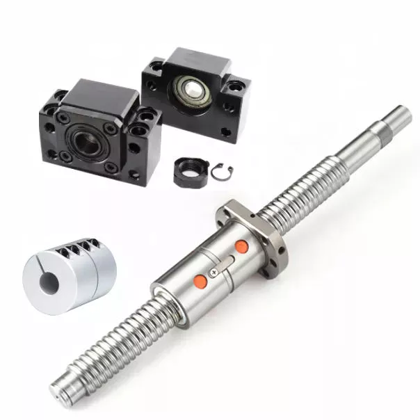
Ball Screws - Dimensions, Applications, and Benefits

Ball screws are popular, lightweight, precision mechanical components. They are commonly used in machinery, gears, and knurled objects. These screw-like parts can be easily maintained and lubricated using oil. This article discusses their dimensions, applications, and benefits. The following sections provide additional information to help you select the right ball screw for your needs. We'll discuss some of the important characteristics of ball screws and what makes them so useful.
air-compressor

Preloading

A key problem with nut-to-ball screw backlash is the ability of the nut to move freely on the threads of the ball screw. To solve this problem, a patented solution was developed. The patent, 4,557,156, describes an innovative method for preloading ball screws and nuts. By applying a preloading nut, the threads of the ball screw are prevented from moving back and forth with the nut.
A mechanical design that involves axial play involves a lot of mass, inertia, and complexity. These characteristics lead to wear and rust problems. Preloading ball screws using a dynamic system reduces mechanical complexity by allowing preload to be adjusted while the mechanism is running. This also reduces the number of mechanical parts and simplifies manufacturing. Thus, the preloading method of the present invention is advantageous.
The servo motors used in the system monitor the output torque and adjust the power to 1 motor in a dynamic way, thus creating a torque differential between the balls. This torque differential in turn creates a preload force between the ball nuts. The servo motors' output torque is controlled in this manner, and the machine's backlash clearance can be precisely controlled. Hence, the machine can perform multiple tasks with increased precision.
Several prior art methods for preloading ball screws are described in detail in FIG. 3. The helical thread grooves of the ball screw 26 and the nut 24 define a pathway for roller balls to travel along. The stylized broken line indicates the general position of the axis of the ball roller screw 26. The corresponding ball screws are used in a number of applications. This technique may be used to manufacture custom-sized screws.

Lubrication

Ball screws are mechanical elements that roll balls through a groove. Improper lubrication can reduce the life of these screw elements. Improper lubrication can lead to shaft damage, malfunction, and decreased performance. This article discusses the importance of proper lubrication and how to do it. You can learn how to properly lubricate ball screws in the following paragraphs. Here are some tips to ensure long-term performance and safety of ball screws.
The first thing you should do is determine the type of lubricant you'll be using. Oils are preferred because they tend to remain inside the ball nut, and grease can build up in it. Oils also tend to have better anti-corrosion properties than grease. However, grease is more likely to be clogged with debris than oils. So, before you choose the lubricant that's right for your screw, make sure you wash it off.
The oil used in ball screw lubrication must be applied at a controlled rate. It can prevent metal-on-metal contact and clean out contaminants as it passes through the ball nut. However, oil as a lubricant is expensive and can contaminate the process if it mixes with the cutting fluid. Grease, on the other hand, is inexpensive, requires fewer applications, and does not contaminate process fluids.
If you use a synthetic oil for lubrication, make sure to choose a viscosity that is appropriate for the operating temperature. Oil viscosity can increase the temperature of the ball screw assembly, and excessive oil can reduce its life. A correct amount of oil will reduce the temperature of the ball screw assembly, while too little will increase friction and wear. Use the following guidelines to determine the right amount of oil for your screw.
air-compressor

Dimensions

Dimensions of ball screws are a very important aspect to consider when determining the best type for your application. Technical acceptance conditions for ball screws specify the allowed deviations during acceptance tests. The tolerance class can also change, depending on the needs of a specific application. The following table lists the most important tolerance values for the full range of screw lengths. This table is a helpful guide when looking for a specific screw. The table below lists the dimensions of common ball screws.
The axial load applied to a ball screw is 0.5 x Fpr / 2Fpr. The minimum screw diameter is known as the root diameter. The axial load causes the screw shaft to deform in a certain way (DL1 and DL2). The elastic deflection induced by the load on a ball screw is called its rigidity. This rigidity is important for calculating sizing parameters for a ball screw.
The preload value of the ball screw affects the dynamic load capacity. A preload of 10 percent is considered adequate, while a value greater than this may compromise the screw's durability. In general, a high preload value will result in a lower dynamic load capacity and greater wear. However, the preload value must be calculated with the relevant screw parameters. This is because a high preload value reduces the screw's durability.
To ensure that your screw meets the specified parameters, the dynamic load capacity must be calculated. This is the amount of force a ball screw will withstand under a specified load. This calculation also includes strength checks. If you are using a ball screw for applications that need extra strength, it may require a safety factor. For example, if the screw is used for double-axial mounting, then the outer ball nut must be inserted into the nut, causing a secondary load.

Applications

The present invention provides a simple, yet highly effective way to mount a ball screw. Its absence of insert slots or through holes makes it simpler to assemble and provides a more uniform nut. The lack of mechanical features also reduces heat treatment issues, and the nut's hardness can be uniformly hardened. As a result, the screw's overall performance is improved. Here are some examples of applications for ball screws.
Preloading is the process of applying force to a ball screw. This increases the rigidity of the screw assembly and eliminates backlash, which is lost motion caused by clearance between the nut and ball. Backlash disrupts repeatability and accuracy. Spacer preloading involves inserting force between 2 ball nuts and transmitting it through the grooves. This method is ideal when preloading is needed in large quantities. In addition to increasing rigidity, preloading can improve accuracy.
Ball screws require careful care in their working surfaces to prevent contamination. Rubber or leather bellows can be used to protect their surfaces, while positive air pressure can be applied to the screw. Preloading eliminates backlash, a common problem among screw assemblies. In addition to the numerous applications for ball screws, they are also critical to computer-controlled motion-control systems and wire bonding. And there are many more examples. So what are the benefits of using these devices?
The spring preloading system uses a spring in between 2 ball nuts, applying tensional forces to the ball nuts. This spring creates grooves in the nut's middle, which facilitates recirculation of the balls. The spring preloading mechanism is more compact than the double nut mechanism, but the lengthening of the lead reduces the ball screw's load capacity. Its compact design makes it ideal for small clearance assemblies.
air-compressor

Maintenance

In addition to performing maintenance tasks yourself, the manufacturer of ball screws should offer reverse engineering services that will enable them to identify specific problems. The process of reverse engineering allows ball screw manufacturers to develop new ball screws and parts. In the event that a ball screw is beyond repair, a manufacturer can often save a significant amount of money by repairing it instead of replacing it. In addition to repairing a ball screw, the manufacturer should also offer free evaluation services for the component. Reconditioning and replacement involve the use of new parts, while reloading and replacement replace the screw.
Performing routine maintenance checks on ball screw assemblies is essential for maintaining optimal performance and extending their service life. Overtime, excessive wear can lead to a variety of problems, including backlash, vibration, and ball bearing noise. In addition, the increased friction increases the required torque for turning a screw, causing system failure and significant downtime. To ensure that a ball screw is fully functional, it must be checked for wear and maintain the proper lubrication system.
Discoloration or pitting on a ball screw indicates that it is in need of repair. The same is true if there are chatter marks in the ball groove. Oftentimes, a ball screw needs a new lubrication seal or wipers. Additionally, it may be missing or over-wearing, which could result in permanent failure. Finally, excessive power draw could be a sign of improper lubrication or improper installation.
Proper maintenance is essential for any machine tool. When performed properly, machine tools can last decades with continuous use. Proper care and maintenance is essential to ensure long life and optimal performance. In addition to improving machine tool uptime, proper maintenance affects the accuracy and repeatability of the end product. Therefore, premium machine tool manufacturers focus on the performance and durability of ball screws. They develop innovative designs and lubricants to optimize the lifespan of their products.

China Good quality Hydraulic Breaker Spare Parts Front Head Back Head and Cylinder     wholesaler China Good quality Hydraulic Breaker Spare Parts Front Head Back Head and Cylinder     wholesaler

China high quality China OEM Factory Manufacturer for High Quality Hydraulic Breaker Main Body Front Head Back Head Cylinder Assy for Rock Breaker Hb20g Hb30g Sb70 Sb81 Sb121 wholesaler

Product Description

Company Introduction:

Company license,certificates,exhibition photos and customers feedbacks:

Production process:

Popular models for world market:

Breaker Parameter:

 Products photos:

product-list-1.html product-list-1.html

WARRANTY: ONE YEAR

Welcome to inquiry and please contact us freely!
contact-info.html


Analytical Approaches to Estimating Contact Pressures in Spline Couplings

A spline coupling is a type of mechanical connection between 2 rotating shafts. It consists of 2 parts - a coupler and a coupling. Both parts have teeth which engage and transfer loads. However, spline couplings are typically over-dimensioned, which makes them susceptible to fatigue and static behavior. Wear phenomena can also cause the coupling to fail. For this reason, proper spline coupling design is essential for achieving optimum performance.
splineshaft

Modeling a spline coupling

Spline couplings are becoming increasingly popular in the aerospace industry, but they operate in a slightly misaligned state, causing both vibrations and damage to the contact surfaces. To solve this problem, this article offers analytical approaches for estimating the contact pressures in a spline coupling. Specifically, this article compares analytical approaches with pure numerical approaches to demonstrate the benefits of an analytical approach.
To model a spline coupling, first you create the knowledge base for the spline coupling. The knowledge base includes a large number of possible specification values, which are related to each other. If you modify 1 specification, it may lead to a warning for violating another. To make the design valid, you must create a spline coupling model that meets the specified specification values.
After you have modeled the geometry, you must enter the contact pressures of the 2 spline couplings. Then, you need to determine the position of the pitch circle of the spline. In Figure 2, the centre of the male coupling is superposed to that of the female spline. Then, you need to make sure that the alignment meshing distance of the 2 splines is the same.
Once you have the data you need to create a spline coupling model, you can begin by entering the specifications for the interface design. Once you have this data, you need to choose whether to optimize the internal spline or the external spline. You'll also need to specify the tooth friction coefficient, which is used to determine the stresses in the spline coupling model 20. You should also enter the pilot clearance, which is the clearance between the tip 186 of a tooth 32 on 1 spline and the feature on the mating spline.
After you have entered the desired specifications for the external spline, you can enter the parameters for the internal spline. For example, you can enter the outer diameter limit 154 of the major snap 54 and the minor snap 56 of the internal spline. The values of these parameters are displayed in color-coded boxes on the Spline Inputs and Configuration GUI screen 80. Once the parameters are entered, you'll be presented with a geometric representation of the spline coupling model 20.

Creating a spline coupling model 20

The spline coupling model 20 is created by a product model software program 10. The software validates the spline coupling model against a knowledge base of configuration-dependent specification constraints and relationships. This report is then input to the ANSYS stress analyzer program. It lists the spline coupling model 20's geometric configurations and specification values for each feature. The spline coupling model 20 is automatically recreated every time the configuration or performance specifications of the spline coupling model 20 are modified.
The spline coupling model 20 can be configured using the product model software program 10. A user specifies the axial length of the spline stack, which may be zero, or a fixed length. The user also enters a radial mating face 148, if any, and selects a pilot clearance specification value of 14.5 degrees or 30 degrees.
A user can then use the mouse 110 to modify the spline coupling model 20. The spline coupling knowledge base contains a large number of possible specification values and the spline coupling design rule. If the user tries to change a spline coupling model, the model will show a warning about a violation of another specification. In some cases, the modification may invalidate the design.
In the spline coupling model 20, the user enters additional performance requirement specifications. The user chooses the locations where maximum torque is transferred for the internal and external splines 38 and 40. The maximum torque transfer location is determined by the attachment configuration of the hardware to the shafts. Once this is selected, the user can click "Next" to save the model. A preview of the spline coupling model 20 is displayed.
The model 20 is a representation of a spline coupling. The spline specifications are entered in the order and arrangement as specified on the spline coupling model 20 GUI screen. Once the spline coupling specifications are entered, the product model software program 10 will incorporate them into the spline coupling model 20. This is the last step in spline coupling model creation.
splineshaft

Analysing a spline coupling model 20

An analysis of a spline coupling model consists of inputting its configuration and performance specifications. These specifications may be generated from another computer program. The product model software program 10 then uses its internal knowledge base of configuration dependent specification relationships and constraints to create a valid three-dimensional parametric model 20. This model contains information describing the number and types of spline teeth 32, snaps 34, and shoulder 36.
When you are analysing a spline coupling, the software program 10 will include default values for various specifications. The spline coupling model 20 comprises an internal spline 38 and an external spline 40. Each of the splines includes its own set of parameters, such as its depth, width, length, and radii. The external spline 40 will also contain its own set of parameters, such as its orientation.
Upon selecting these parameters, the software program will perform various analyses on the spline coupling model 20. The software program 10 calculates the nominal and maximal tooth bearing stresses and fatigue life of a spline coupling. It will also determine the difference in torsional windup between an internal and an external spline. The output file from the analysis will be a report file containing model configuration and specification data. The output file may also be used by other computer programs for further analysis.
Once these parameters are set, the user enters the design criteria for the spline coupling model 20. In this step, the user specifies the locations of maximum torque transfer for both the external and internal spline 38. The maximum torque transfer location depends on the configuration of the hardware attached to the shafts. The user may enter up to 4 different performance requirement specifications for each spline.
The results of the analysis show that there are 2 phases of spline coupling. The first phase shows a large increase in stress and vibration. The second phase shows a decline in both stress and vibration levels. The third stage shows a constant meshing force between 300N and 320N. This behavior continues for a longer period of time, until the final stage engages with the surface.
splineshaft

Misalignment of a spline coupling

A study aimed to investigate the position of the resultant contact force in a spline coupling engaging teeth under a steady torque and rotating misalignment. The study used numerical methods based on Finite Element Method (FEM) models. It produced numerical results for nominal conditions and parallel offset misalignment. The study considered 2 levels of misalignment - 0.02 mm and 0.08 mm - with different loading levels.
The results showed that the misalignment between the splines and rotors causes a change in the meshing force of the spline-rotor coupling system. Its dynamics is governed by the meshing force of splines. The meshing force of a misaligned spline coupling is related to the rotor-spline coupling system parameters, the transmitting torque, and the dynamic vibration displacement.
Despite the lack of precise measurements, the misalignment of splines is a common problem. This problem is compounded by the fact that splines usually feature backlash. This backlash is the result of the misaligned spline. The authors analyzed several splines, varying pitch diameters, and length/diameter ratios.
A spline coupling is a two-dimensional mechanical system, which has positive backlash. The spline coupling is comprised of a hub and shaft, and has tip-to-root clearances that are larger than the backlash. A form-clearance is sufficient to prevent tip-to-root fillet contact. The torque on the splines is transmitted via friction.
When a spline coupling is misaligned, a torque-biased thrust force is generated. In such a situation, the force can exceed the torque, causing the component to lose its alignment. The two-way transmission of torque and thrust is modeled analytically in the present study. The analytical approach provides solutions that can be integrated into the design process. So, the next time you are faced with a misaligned spline coupling problem, make sure to use an analytical approach!
In this study, the spline coupling is analyzed under nominal conditions without a parallel offset misalignment. The stiffness values obtained are the percentage difference between the nominal pitch diameter and load application diameter. Moreover, the maximum percentage difference in the measured pitch diameter is 1.60% under a torque of 5000 N*m. The other parameter, the pitch angle, is taken into consideration in the calculation.

China high quality China OEM Factory Manufacturer for High Quality Hydraulic Breaker Main Body Front Head Back Head Cylinder Assy for Rock Breaker Hb20g Hb30g Sb70 Sb81 Sb121     wholesaler China high quality China OEM Factory Manufacturer for High Quality Hydraulic Breaker Main Body Front Head Back Head Cylinder Assy for Rock Breaker Hb20g Hb30g Sb70 Sb81 Sb121     wholesaler